Full Text Searchable PDF User Manual

Panasonic Consumer
Electronics Company,
Division of Panasonic
Corporation of North America
One Panasonic Way, Secaucus,
New Jersey 07094
http://www.panasonic.com
Panasonic Puerto Rico, Inc.
Ave. 65 de Infanteria, Km. 9.5
San Gabriel Industrial Park,
Carolina, Puerto Rico 00985
http://www.panasonic.com
Panasonic Canada Inc.
5770 Ambler Drive,
Mississauga, Ontario
L4W 2T3
http://www.panasonic.ca
CN-NVD905U
Installation
Dual DIN in-dash HDD Mobile Navigation System with 7
Widescreen Color
LCD Monitor/DVD Receiver
Système de navigation embarqué à disque dur de format 2-DIN
avec récepteur DVD/moniteur couleur ACL grand écran de 7 po
Sistema de navegación portátil de doble DIN para tablero de mandos, con
disco duro y monitor LCD panorámico de 7
en color y receptor con DVD
CN-NVD905U
Installation Instructions
Instructions d’installation
Instrucciones de instalación
Read the “Safety information” presented in the Operating Instructions before
mounting or connecting this product.
Avant le montage ou le branchement du présent produit, veuillez lire les
« informations sur la sécurité » décrites dans le manuel d’instructions.
Lea la “Información de seguridad” que aparece en las Instrucciones de
funcionamiento antes de montar o conectar este producto.
© 2007 Matsushita Electric Industrial Co., Ltd. All Rights Reserved.
YEFM294342 F0107-1037
© 2007 Matsushita Electric Industrial Co., Ltd. Tous droits réservés.
Printed in Japan
Imprimé au Japon
Impreso en Japan
Contents
Installation hardware
...........................................2
Contents
....................................................................3
Installation guide
...................................................4
Mounting and removing the unit
......................6
Mounting the GPS antenna
................................8
Electrical connections
........................................10
External unit connections
.................................12
Note:
The number in parentheses underneath each
accessory part name is the part number for
maintenance and service.
Accessories and their parts numbers are subject
to modifi cation without prior notice due to
improvements.
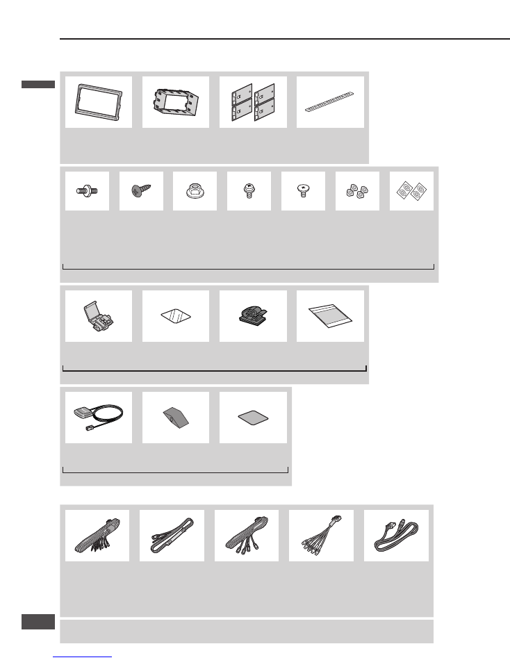
Use the supplied screws for installation exclusively. In
case of loss, please order the specifi c screw.
Installation hardware
For installation
For wiring
Trim plate
Mounting collar
Mounting spring
Rear support strap
YEFC041589B
Qty: 1
YEFG013081A
Qty: 1
YEFX0052513
Qty: 4
YEFG04019
Qty: 1
Mounting
bolt
(5 mm
)
Tapping
screw
(5 mm
16 mm)
Hex. nut
(5 mm
)
Round head
screw
(5 mm
6 mm)
Flat-Head
screw
(5 mm
6 mm)
Spacer
Double-
Faced
Adhesive
Tape
Qty: 1
Qty: 1
Qty: 1
Qty: 4
Qty: 8
Qty: 4
Qty: 4
YEP0FZ5810 Qty: 1
Clip connector
Protection sheet
Cord clamper
Wiping Cloth
Qty: 4
Qty: 1
Qty: 5
Qty: 1
YEP0FZ5811 Qty: 1
GPS antenna
Rubber water seal
Metal sheet
Qty: 1
Qty: 1
Qty: 1
YEP0FZ5726 Qty: 1
Power connector
Speed Pulse Cable
Vehicle signal
connector
AV connector
Rear view camera –
RCA conversion
cable
YEAJ012837A
Qty: 1
YEAJ071554
Qty: 1
YEAJ071720
Qty: 1
K1V912Y10001
Qty: 1
YEAJ071818
Qty: 1
Car navigation unit, Instruction kit
(
Operating Instructions)
English
Français
Español
English
English
2
3
3
2

Contents
Installation hardware
...........................................2
Contents
....................................................................3
Installation guide
...................................................4
Mounting and removing the unit
......................6
Mounting the GPS antenna
................................8
Electrical connections
........................................10
External unit connections
.................................12
Note:
The number in parentheses underneath each
accessory part name is the part number for
maintenance and service.
Accessories and their parts numbers are subject
to modifi cation without prior notice due to
improvements.
Use the supplied screws for installation exclusively. In
case of loss, please order the specifi c screw.
Installation hardware
For installation
For wiring
Trim plate
Mounting collar
Mounting spring
Rear support strap
YEFC041589B
Qty: 1
YEFG013081A
Qty: 1
YEFX0052513
Qty: 4
YEFG04019
Qty: 1
Mounting
bolt
(5 mm
)
Tapping
screw
(5 mm
16 mm)
Hex. nut
(5 mm
)
Round head
screw
(5 mm
6 mm)
Flat-Head
screw
(5 mm
6 mm)
Spacer
Double-
Faced
Adhesive
Tape
Qty: 1
Qty: 1
Qty: 1
Qty: 4
Qty: 8
Qty: 4
Qty: 4
YEP0FZ5810 Qty: 1
Clip connector
Protection sheet
Cord clamper
Wiping Cloth
Qty: 4
Qty: 1
Qty: 5
Qty: 1
YEP0FZ5811 Qty: 1
GPS antenna
Rubber water seal
Metal sheet
Qty: 1
Qty: 1
Qty: 1
YEP0FZ5726 Qty: 1
Power connector
Speed Pulse Cable
Vehicle signal
connector
AV connector
Rear view camera –
RCA conversion
cable
YEAJ012837A
Qty: 1
YEAJ071554
Qty: 1
YEAJ071720
Qty: 1
K1V912Y10001
Qty: 1
YEAJ071818
Qty: 1
Car navigation unit, Instruction kit
(
Operating Instructions)
English
Français
Español
English
English
2
3
3
2
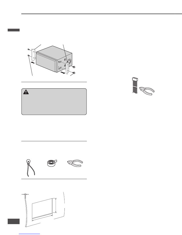
Transportation bracket removal
Be sure to remove the transportation brackets before
use (installation).
Use round head screws (5 mm
6 mm) for installation.
(
page 7)
Be careful not to lose these screws.
Transportation Bracket
Round head screw (5 mm
6 mm)
Before installation
Installation guide
Required tools
You’ll need a screwdriver and the following:
12 V DC
Test Bulb
Electrical
Tape
Side-Cut
Pliers
Dashboard specifi cations
Thickness
MIN. 4.75 mm {3/16
}
MAX. 5.56 mm {7/32
}
112 mm {4
3
/
8
}
182 mm {7
3
/
16
}
Identify all leads
The fi rst step in installation is to identify all the car wires
you will use when hooking up this unit.
As you identify each wire, we suggest that you label it
using masking tape and a permanent marker. This will
help avoid confusion when making connections later.
Note:
Do not connect the power connector to this unit until
you have made all connections. If there are no plastic
caps on the hooking wires, insulate all exposed leads
with electrical tape until you are ready to use them.
Identify the leads in the following order.
Power lead
If your car has a radio or is
pre-wired for one:
Cut the connector wires one at a
time from the plug (leaving the
leads as long as possible) so
that you can work with individual
leads. Turn the ignition on to the
accessory position, and ground
one lead of the test bulb to the
chassis.
Touch the other lead of the test bulb to each of the
exposed wires from the cut radio connector plug. Touch
one wire at a time until you fi nd the outlet that causes
the test bulb to light.
Now turn the ignition off and then on. If the bulb also
turns off and on, that outlet is the car power lead.
If your car is not wired for an audio unit:
Go to the fuse block and fi nd the fuse port for radio
(RADIO) accessory (ACC) or ignition (IGN).
Battery lead
If this unit has a yellow lead, you will need to locate
the car’s battery lead. Otherwise you may ignore this
procedure. (The yellow battery lead provides continuous
power to maintain a clock or other functions.)
If your car has a radio or is pre-wired for one:
With the ignition and headlights off, identify the car
battery lead by grounding one lead of the test bulb to the
chassis and checking the remaining exposed wires from
the cut radio connector plug.
If your car is not wired for an audio unit:
Go to the fuse block and fi nd the fuse port for the
battery, usually marked BAT.
Speakers (not supplied)
Identify the car speaker leads. There are two leads for
each speaker, usually color coded.
A handy way to identify the speaker leads and the
speaker they are connected to is to test the leads using a
1.5 V AA battery as follows.
Hold one lead against one pole of the battery and stroke
the other lead across the other pole. You will hear a
scraping sound in a speaker if you are holding a speaker
lead.
If not, keep testing different lead combinations until you
have located all the speaker leads. When you label them,
include the speaker location for each.
Connect all leads
Now that you have identifi ed all the wires in the car,
you’re ready to begin connecting them to this unit wires.
Electrical Connections (
page 10 – 11) shows the
proper connections and color coding of the leads.
We strongly recommend that you test the unit before
making a fi nal installation.
You can set the unit on the fl oor and make temporary
connections to test the unit. Use electrical tape to cover
all exposed wires.
Important:
Connect the red power lead last, after you have made
and insulated all other connections.
Ground
Connect the black ground lead of the power connector to
the metal car chassis.
Speakers
Connect the speaker wires. See the wiring diagram for
the proper hookups. Follow the diagram carefully to
avoid damaging the speakers and this unit.
The speakers used must be able to handle more than
50 W of audio power. If using optional audio power,
the speakers should be able to handle the maximum
amplifi er output power. Speakers with low input ratings
can be damaged.
Speaker impedance should measure 4 – 8
, which is
typically marked on most speakers. Lower or higher
impedance speakers will affect output and can cause
both speaker and this unit damage.
Battery
Connect the yellow battery lead to the correct radio wire
or to the battery fuse port on the fuse block.
Equipment
Connect any optional equipment according to the
instructions furnished with the equipment. Read the
operating and installation instructions of any equipment
you will connect to this unit.
Power
Connect the red power lead to the correct car radio wire
or to the appropriate fuse port on the fuse block.
If this unit functions properly with all these connections
made, disconnect the wires and proceed to the fi nal
installation.
Final installation
Lead connections
Connect all wires, making sure that each connection is
insulated and secure. Bundle all loose wires and fasten
them with tape so they will not fall down later. Now
insert this unit into the mounting collar.
Congratulations! After making a few fi nal checks, the
new unit is ready for use.
Final checks
1. Make sure that all wires are properly connected and
insulated.
2. Make sure that this unit is securely held in the
mounting collar.
3. Turn on the ignition to check the unit for proper
operation.
If you have diffi culties, consult your nearest authorized
professional installer for assistance.
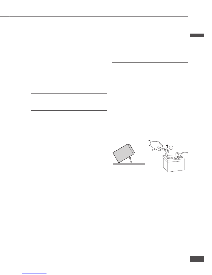
Precautions
Disconnect the cable from the negative (–) battery
terminal.
Unit should be installed in a horizontal position
with the front end up at a convenient angle, but less
than 30°.
0 – 30°
This unit should be professionally installed. In case of
diffi culty, please consult with your nearest professional
installer.
1. This unit only operates in a 12 V DC negative ground
system.
2. Follow the electrical connections carefully
(
page 10 – 11). Failure to do so may result in
damage to the unit.
3. Connect the power lead after all other connections are
made.
4. Be sure to connect the battery lead (yellow) to the
positive terminal (+) of the battery or fuse block (BAT)
terminal.
5. Insulate all exposed wires to prevent short circuiting.
6. Secure all loose wires after installing the unit.
7. Please carefully read the operating and installation
instructions of the respective equipment before
connecting it to this unit.
Warning
This product is designed for operation with a negative
grounded 12 V DC battery system. Never operate
this product with other battery systems, especially
a 24 V DC battery system. If it is used in the wrong
type of car, it may cause a fi re or an accident.
Do not press the panel forcefully.
Do not scratch the panel with fi ngernails or any hard
objects.
Do not bump the front panel.
Failure to observe the above may damage or break
the glass on the surface of the touch panel.
English
English
4
5
5
4
Transportation bracket removal
Be sure to remove the transportation brackets before
use (installation).
Use round head screws (5 mm
6 mm) for installation.
(
page 7)
Be careful not to lose these screws.
Transportation Bracket
Round head screw (5 mm
6 mm)
Before installation
Installation guide
Required tools
You’ll need a screwdriver and the following:
12 V DC
Test Bulb
Electrical
Tape
Side-Cut
Pliers
Dashboard specifi cations
Thickness
MIN. 4.75 mm {3/16
}
MAX. 5.56 mm {7/32
}
112 mm {4
3
/
8
}
182 mm {7
3
/
16
}
Identify all leads
The fi rst step in installation is to identify all the car wires
you will use when hooking up this unit.
As you identify each wire, we suggest that you label it
using masking tape and a permanent marker. This will
help avoid confusion when making connections later.
Note:
Do not connect the power connector to this unit until
you have made all connections. If there are no plastic
caps on the hooking wires, insulate all exposed leads
with electrical tape until you are ready to use them.
Identify the leads in the following order.
Power lead
If your car has a radio or is
pre-wired for one:
Cut the connector wires one at a
time from the plug (leaving the
leads as long as possible) so
that you can work with individual
leads. Turn the ignition on to the
accessory position, and ground
one lead of the test bulb to the
chassis.
Touch the other lead of the test bulb to each of the
exposed wires from the cut radio connector plug. Touch
one wire at a time until you fi nd the outlet that causes
the test bulb to light.
Now turn the ignition off and then on. If the bulb also
turns off and on, that outlet is the car power lead.
If your car is not wired for an audio unit:
Go to the fuse block and fi nd the fuse port for radio
(RADIO) accessory (ACC) or ignition (IGN).
Battery lead
If this unit has a yellow lead, you will need to locate
the car’s battery lead. Otherwise you may ignore this
procedure. (The yellow battery lead provides continuous
power to maintain a clock or other functions.)
If your car has a radio or is pre-wired for one:
With the ignition and headlights off, identify the car
battery lead by grounding one lead of the test bulb to the
chassis and checking the remaining exposed wires from
the cut radio connector plug.
If your car is not wired for an audio unit:
Go to the fuse block and fi nd the fuse port for the
battery, usually marked BAT.
Speakers (not supplied)
Identify the car speaker leads. There are two leads for
each speaker, usually color coded.
A handy way to identify the speaker leads and the
speaker they are connected to is to test the leads using a
1.5 V AA battery as follows.
Hold one lead against one pole of the battery and stroke
the other lead across the other pole. You will hear a
scraping sound in a speaker if you are holding a speaker
lead.
If not, keep testing different lead combinations until you
have located all the speaker leads. When you label them,
include the speaker location for each.
Connect all leads
Now that you have identifi ed all the wires in the car,
you’re ready to begin connecting them to this unit wires.
Electrical Connections (
page 10 – 11) shows the
proper connections and color coding of the leads.
We strongly recommend that you test the unit before
making a fi nal installation.
You can set the unit on the fl oor and make temporary
connections to test the unit. Use electrical tape to cover
all exposed wires.
Important:
Connect the red power lead last, after you have made
and insulated all other connections.
Ground
Connect the black ground lead of the power connector to
the metal car chassis.
Speakers
Connect the speaker wires. See the wiring diagram for
the proper hookups. Follow the diagram carefully to
avoid damaging the speakers and this unit.
The speakers used must be able to handle more than
50 W of audio power. If using optional audio power,
the speakers should be able to handle the maximum
amplifi er output power. Speakers with low input ratings
can be damaged.
Speaker impedance should measure 4 – 8
, which is
typically marked on most speakers. Lower or higher
impedance speakers will affect output and can cause
both speaker and this unit damage.
Battery
Connect the yellow battery lead to the correct radio wire
or to the battery fuse port on the fuse block.
Equipment
Connect any optional equipment according to the
instructions furnished with the equipment. Read the
operating and installation instructions of any equipment
you will connect to this unit.
Power
Connect the red power lead to the correct car radio wire
or to the appropriate fuse port on the fuse block.
If this unit functions properly with all these connections
made, disconnect the wires and proceed to the fi nal
installation.
Final installation
Lead connections
Connect all wires, making sure that each connection is
insulated and secure. Bundle all loose wires and fasten
them with tape so they will not fall down later. Now
insert this unit into the mounting collar.
Congratulations! After making a few fi nal checks, the
new unit is ready for use.
Final checks
1. Make sure that all wires are properly connected and
insulated.
2. Make sure that this unit is securely held in the
mounting collar.
3. Turn on the ignition to check the unit for proper
operation.
If you have diffi culties, consult your nearest authorized
professional installer for assistance.
Precautions
Disconnect the cable from the negative (–) battery
terminal.
Unit should be installed in a horizontal position
with the front end up at a convenient angle, but less
than 30°.
0 – 30°
This unit should be professionally installed. In case of
diffi culty, please consult with your nearest professional
installer.
1. This unit only operates in a 12 V DC negative ground
system.
2. Follow the electrical connections carefully
(
page 10 – 11). Failure to do so may result in
damage to the unit.
3. Connect the power lead after all other connections are
made.
4. Be sure to connect the battery lead (yellow) to the
positive terminal (+) of the battery or fuse block (BAT)
terminal.
5. Insulate all exposed wires to prevent short circuiting.
6. Secure all loose wires after installing the unit.
7. Please carefully read the operating and installation
instructions of the respective equipment before
connecting it to this unit.
Warning
This product is designed for operation with a negative
grounded 12 V DC battery system. Never operate
this product with other battery systems, especially
a 24 V DC battery system. If it is used in the wrong
type of car, it may cause a fi re or an accident.
Do not press the panel forcefully.
Do not scratch the panel with fi ngernails or any hard
objects.
Do not bump the front panel.
Failure to observe the above may damage or break
the glass on the surface of the touch panel.
English
English
4
5
5
4
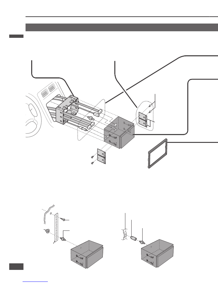
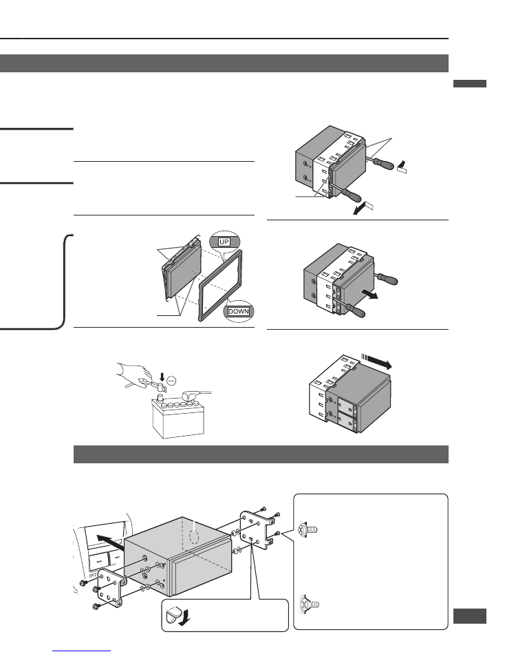
Hook
Mounting procedures (A)
(When using Mounting collar
)
Note:
The car model, installation conditions and
combination of the units used may impose some
restrictions on opening and closing the monitor
as well as on the angle and position to which the
monitor can be adjusted.
(a) Using the Rear support strap
.
Fire wall of car
3 mm
Rear support strap
Tapping screw
(5 mm
16 mm)
Mounting bolt
(5 mm
)
Hex. nut
(5 mm
)
(b) Using the Rubber cushion (option)
Rubber bushing (option)
Rear support bracket
(Provided on the car)
Mounting bolt
(5 mm
)
Mounting and removing the unit
Use the brackets supplied with your car when mounting this unit. The bracket shape and mounting method vary with
car manufacturers, car types and manufacturing year. Please consult your nearest dealer or installer.
Select mounting screws according to the hole
positions and hole shape of the bracket.
Round head screw
(5 mm
6 mm)
Mounting procedures (B)
(When not using Mounting collar
)
Note:
Use pliers to bend the fi ngers
on the bracket vertically.
Insert the Mounting collar
into the dashboard, and bend
the mounting tabs out with a
screwdriver.
Attach the mounting spring
to the unit.
Establish the rear connection of
the unit.
After fi xing Power connector
, fi x the rear of
the unit to the car body by either method (a) or (b).
Insert the unit into Mounting
collar
.
Secure the clamp plate of Mounting collar
to the hook.
Insert trim plate
.
After installation reconnect the
negative (–) battery terminal.
Snapping point
Snapping point
Flat-Head screw
(5 mm
6 mm)
Mounting spring
Cooling fan
Do not block the area around it.
Note:
Reuse the round head screws that
fi xed the transportation brackets for
two more positions. (
page 4)
Flat-Head screw
(5 mm
6 mm)
IMPORTANT
When this unit is installed in a dashboard, ensure that there is suffi cient air fl ow around the unit to prevent damage
from overheating. Do not block any ventilation holes on the unit.
Removing procedures
Hold the unit and pull it forward until the hooks are
visible.
Remove the screwdrivers and pull the unit out with
both hands.
Method for fi xing the rear of the unit
Hook
Insert two fl athead screwdrivers between the unit and
the mounting collar, then detach the four hooks.
English
English
6
7
7
6
Hook
Mounting procedures (A)
(When using Mounting collar
)
Note:
The car model, installation conditions and
combination of the units used may impose some
restrictions on opening and closing the monitor
as well as on the angle and position to which the
monitor can be adjusted.
(a) Using the Rear support strap
.
Fire wall of car
3 mm
Rear support strap
Tapping screw
(5 mm
16 mm)
Mounting bolt
(5 mm
)
Hex. nut
(5 mm
)
(b) Using the Rubber cushion (option)
Rubber bushing (option)
Rear support bracket
(Provided on the car)
Mounting bolt
(5 mm
)
Mounting and removing the unit
Use the brackets supplied with your car when mounting this unit. The bracket shape and mounting method vary with
car manufacturers, car types and manufacturing year. Please consult your nearest dealer or installer.
Select mounting screws according to the hole
positions and hole shape of the bracket.
Round head screw
(5 mm
6 mm)
Mounting procedures (B)
(When not using Mounting collar
)
Note:
Use pliers to bend the fi ngers
on the bracket vertically.
Insert the Mounting collar
into the dashboard, and bend
the mounting tabs out with a
screwdriver.
Attach the mounting spring
to the unit.
Establish the rear connection of
the unit.
After fi xing Power connector
, fi x the rear of
the unit to the car body by either method (a) or (b).
Insert the unit into Mounting
collar
.
Secure the clamp plate of Mounting collar
to the hook.
Insert trim plate
.
After installation reconnect the
negative (–) battery terminal.
Snapping point
Snapping point
Flat-Head screw
(5 mm
6 mm)
Mounting spring
Cooling fan
Do not block the area around it.
Note:
Reuse the round head screws that
fi xed the transportation brackets for
two more positions. (
page 4)
Flat-Head screw
(5 mm
6 mm)
IMPORTANT
When this unit is installed in a dashboard, ensure that there is suffi cient air fl ow around the unit to prevent damage
from overheating. Do not block any ventilation holes on the unit.
Removing procedures
Hold the unit and pull it forward until the hooks are
visible.
Remove the screwdrivers and pull the unit out with
both hands.
Method for fi xing the rear of the unit
Hook
Insert two fl athead screwdrivers between the unit and
the mounting collar, then detach the four hooks.
English
English
6
7
7
6
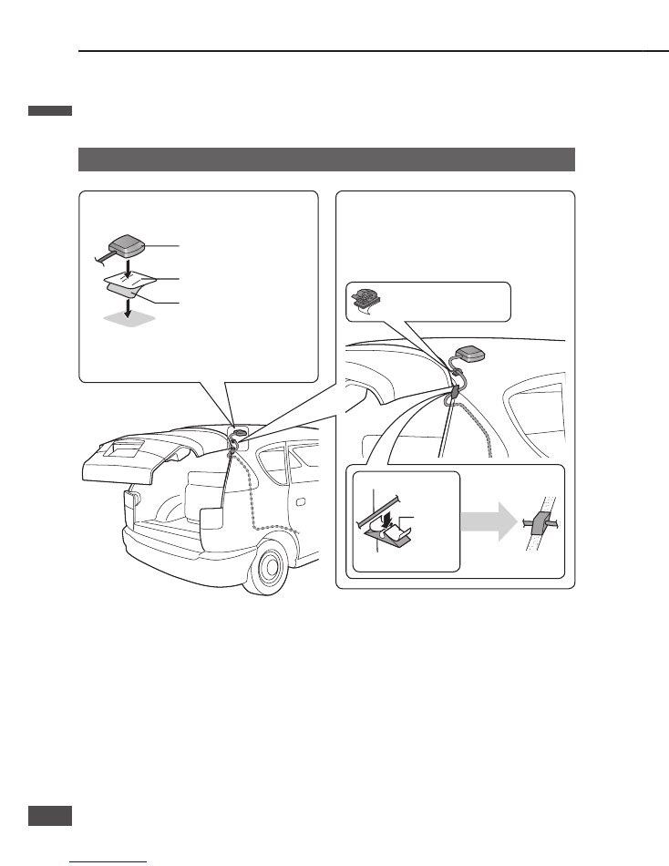
Route the cord so that it does not
allow rainwater into the vehicle.
If the vehicle is a hatchback, allow enough slack
in the cord so that it does not get pulled when the
rear door is opened or closed.
Note:
Keep paint, wax, etc. off the GPS antenna. Also,
remove substances such as snow from the antenna
when they accumulate. These substances impede GPS
signal reception.
Always remove the GPS antenna before using a car
wash. When removing it, take care not to pull on the
cord, as that could cause damage or a malfunction.
* Mounting the antenna close to a luggage carrier
or on the trunk lid impairs reception of signals
from the GPS satellites.
GPS antenna
Protection sheet
Peel the backing paper off.
Cord clamper
Clamp the cord at key points.
GPS antenna cord
Rubber water seal
Peel the
backing
paper off.
Turn over
Place parallel to the
trunk gasket.
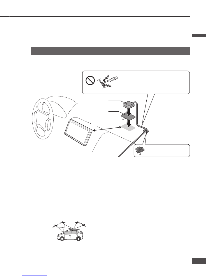
Mount the antenna horizontally, in the center of the dashboard and close to the
windscreen.
More than 20 cm
GPS antenna
Metal sheet
Do not use the tip of a screwdriver or similar
pointed implement to push the cord, as that could
damage the cord or cause a malfunction.
Cord clamper
Clamp the cable at key points.
Note:
Mounting the antenna inside the vehicle impedes
reception, and may cause incorrect indication of
vehicle position, depending on the strength of the
signal. Mount the antenna outside the vehicle if
reception is unsatisfactory.
The GPS signal may be blocked by the shape of the
vehicle body or by a windshield or side window.
Mounting the GPS antenna
Preparation:
Wipe all dirt (oil, dust, etc.) off the mounting surface, and dry any moisture.
If the air temperature is low, use a hair drier, etc. to warm the mounting surface.
To avoid interference, mount the GPS antenna at least 10 cm away from any other antenna.
External mounting (recommended)
Mount the GPS antenna on a fl at part
of the roof.
Mounting on the dashboard or rear tray
Be sure to use the metal sheet provided.
Do not fold it or cut it smaller.
If you bundle up the excess antenna cord, keep it at
least 30 cm away from the navigation unit.
Keep watches and magnetic cards away from the
GPS antenna. The watch or card could malfunction or
become unusable.
English
English
8
9
9
8
Route the cord so that it does not
allow rainwater into the vehicle.
If the vehicle is a hatchback, allow enough slack
in the cord so that it does not get pulled when the
rear door is opened or closed.
Note:
Keep paint, wax, etc. off the GPS antenna. Also,
remove substances such as snow from the antenna
when they accumulate. These substances impede GPS
signal reception.
Always remove the GPS antenna before using a car
wash. When removing it, take care not to pull on the
cord, as that could cause damage or a malfunction.
* Mounting the antenna close to a luggage carrier
or on the trunk lid impairs reception of signals
from the GPS satellites.
GPS antenna
Protection sheet
Peel the backing paper off.
Cord clamper
Clamp the cord at key points.
GPS antenna cord
Rubber water seal
Peel the
backing
paper off.
Turn over
Place parallel to the
trunk gasket.
Mount the antenna horizontally, in the center of the dashboard and close to the
windscreen.
More than 20 cm
GPS antenna
Metal sheet
Do not use the tip of a screwdriver or similar
pointed implement to push the cord, as that could
damage the cord or cause a malfunction.
Cord clamper
Clamp the cable at key points.
Note:
Mounting the antenna inside the vehicle impedes
reception, and may cause incorrect indication of
vehicle position, depending on the strength of the
signal. Mount the antenna outside the vehicle if
reception is unsatisfactory.
The GPS signal may be blocked by the shape of the
vehicle body or by a windshield or side window.
Mounting the GPS antenna
Preparation:
Wipe all dirt (oil, dust, etc.) off the mounting surface, and dry any moisture.
If the air temperature is low, use a hair drier, etc. to warm the mounting surface.
To avoid interference, mount the GPS antenna at least 10 cm away from any other antenna.
External mounting (recommended)
Mount the GPS antenna on a fl at part
of the roof.
Mounting on the dashboard or rear tray
Be sure to use the metal sheet provided.
Do not fold it or cut it smaller.
If you bundle up the excess antenna cord, keep it at
least 30 cm away from the navigation unit.
Keep watches and magnetic cards away from the
GPS antenna. The watch or card could malfunction or
become unusable.
English
English
8
9
9
8
SPEED
ILLUMINATION
SIDE BRAKE
REVERSE
P
R
N
D
2
L
VIDEO-OUT
S.W-OUT
AV-IN
PRE-OUT FRONT
ACC 3 A
3 A
ANT CONT MAX 0.1 A
BATTERY 15 A
BATTERY 5 A
5 A
FRONT L
FRONT R
AMP CONT MAX 0.1 A
REAR L
REAR R
PRE-OUT REAR
REMOTE-OUT
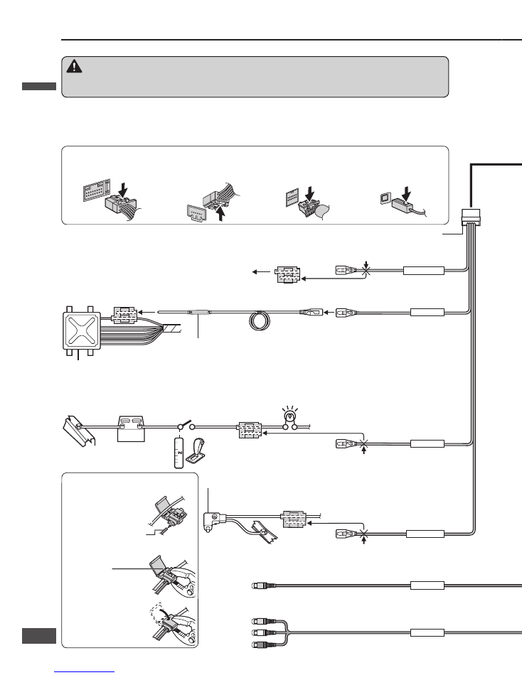
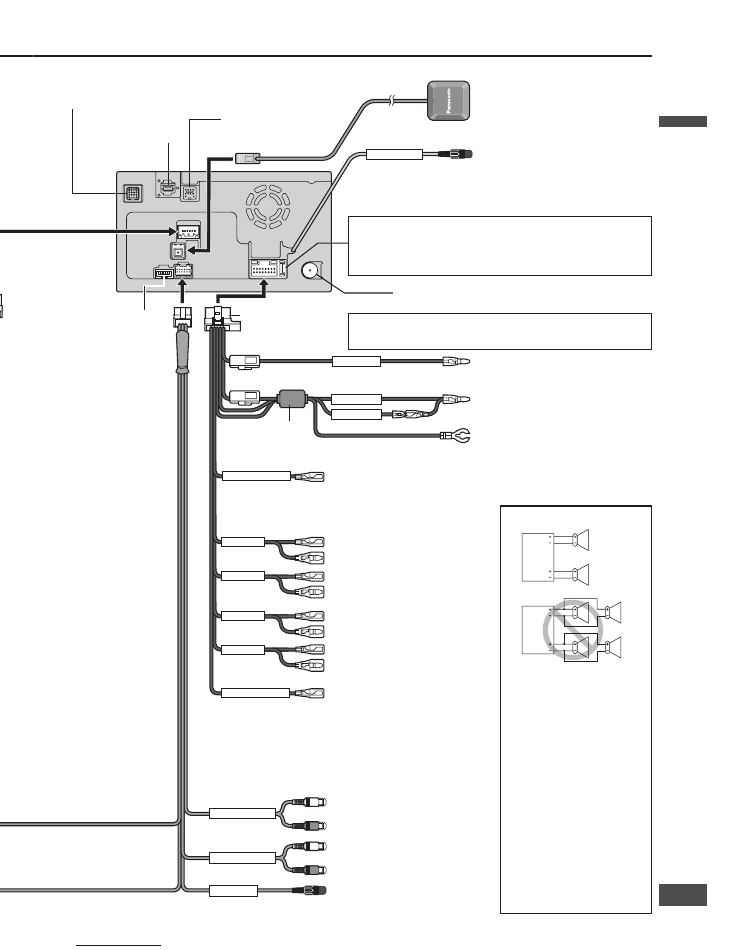
Electrical connections
CN-NVD905U (Rear)
To prevent from damage to the unit, be sure to follow the wiring diagrams below.
Be sure to fully plug in the connectors. Secure them with clamps and tapes.
All other installation methods require the use of dedicated metal fi ttings. Consult with a qualifi ed servicing engineer
or your dealer if other methods are required.
(R) (Red)
(L) (White)
(Yellow)
Video input terminal (AV-IN)
Connect to a VCR, camcorder or TV tuner.
(
page 13)
Video output terminal (VIDEO-OUT)
Connect to a rear monitor. (
page 12)
Radio antenna connector (RADIO ANT IN)
Motor antenna relay control lead
(Blue)
To motor antenna (Max. 100 mA)
External amplifi er control power
lead
(Blue/white stripe)
Power lead
(Red)
To ACC power, +12 V DC.
Battery lead
(Yellow)
To the car battery, continuous +12 V DC.
Ground lead
(Black)
To a clean, bare metallic part of the
car chassis.
Speaker connections
Do not connect more than
one speaker to one set of
speaker leads (except for
connecting to a tweeter).
Do not use a 3-wire type
speaker system having a
common earth lead.
Use ungrounded speakers
only.
Allowable input : 50 W or
more.
Impedance : 4 – 8
Use of speakers which
do not match the
specifi cations can cause
burning, smoking or
damage of the speakers.
Power connector
Front right +
(Gray)
Front right –
(Gray/black stripe)
Front left +
(White)
Front left –
(White/black stripe)
Rear right +
(Violet)
Rear right –
(Violet/black stripe)
Rear left +
(Green)
Rear left –
(Green/black stripe)
Reverse lead
(Violet/white stripe)
To the positive (+) lead of the reverse
lamp (the lamp with a clear lens that
lights when the transmission gear is
shifted into the reverse position).
Car chassis
Clip connector
Reverse lamp
Battery
Transmission gear
Bundle excess cord. Do not cut it.
Clip connector
Car chassis
Side brake (Parking brake) switch
Side brake (Parking brake) connection
lead
(Bright green)
When the side brake (parking brake) lever is
engaged, the unit is grounded by the chassis.
Clip connector
Illumination lead
(Orange/white stripe)
To the vehicle lighting power supply
GPS antenna
To an external amplifi er or a power control lead of the TV tuner.
Connect both the power control lead of the TV tuner and the
amplifi er control connector of the external amplifi er when the
TV tuner and external amplifi er are connected at the same
time.
REMOTE OUT connector
To the REMOTE IN connector of a
TV tuner
System-up connector
To external devices equipped with system-up connector.
Data 1 connector
(available in future)
Data 2 connector
(available in future)
Rear view camera
connector
Connect a rear view
camera (
page 12)
Pre-out subwoofer connector
(Mono)
To an external amplifi er.
Pre-out connector (Front)
To an external amplifi er.
Pre-out connector (Rear)
To an external amplifi er.
This lead is not intended for use with a switch actuated
power antenna.
(Yellow)
Fuse (3 A)
Fuse (5 A)
Speed Pulse Cable
(Pink)
Clip connector
Engine control computer unit (ECU)
This is a circuit protector. Do not cut it off, and be sure to connect it in the
direction of the vehicle speed reading point as is.
Vehicle speed signal lead
(Pink)
When disconnecting a locked cable, press the lock in the arrowed direction while removing the connector.
Pulling too strongly will break the connector. Check that the lock is disengaged before trying to disconnect the connector.
Power connector
Vehicle signal connector
AV connector
GPS antenna connector
AV connector
Vehicle signal connector
How to attach a clip connector
Insert the cable into
the clip connector.
Vehicle-side wiring cable
Parking brake connection
lead of this unit (Example)
Press the element
into place.
Close the cover.
This navigation system cannot be installed in a vehicle that does
not have an ACC (accessory) position on the ignition switch.
Noise fi lter
Fuse (15 A)
Refer fuse replacement to your nearest authorized Panasonic
Servicenter. Do not attempt fuse replacement by yourself.
Warning
This product is designed for operation with a negative grounded 12 V DC battery system. Never operate this product with other
battery systems, especially a 24 V DC battery system. If it is used in the wrong type of car, it may cause a fi re or an accident.
English
English
10
11
11
10
SPEED
ILLUMINATION
SIDE BRAKE
REVERSE
P
R
N
D
2
L
VIDEO-OUT
S.W-OUT
AV-IN
PRE-OUT FRONT
ACC 3 A
3 A
ANT CONT MAX 0.1 A
BATTERY 15 A
BATTERY 5 A
5 A
FRONT L
FRONT R
AMP CONT MAX 0.1 A
REAR L
REAR R
PRE-OUT REAR
REMOTE-OUT
Electrical connections
CN-NVD905U (Rear)
To prevent from damage to the unit, be sure to follow the wiring diagrams below.
Be sure to fully plug in the connectors. Secure them with clamps and tapes.
All other installation methods require the use of dedicated metal fi ttings. Consult with a qualifi ed servicing engineer
or your dealer if other methods are required.
(R) (Red)
(L) (White)
(Yellow)
Video input terminal (AV-IN)
Connect to a VCR, camcorder or TV tuner.
(
page 13)
Video output terminal (VIDEO-OUT)
Connect to a rear monitor. (
page 12)
Radio antenna connector (RADIO ANT IN)
Motor antenna relay control lead
(Blue)
To motor antenna (Max. 100 mA)
External amplifi er control power
lead
(Blue/white stripe)
Power lead
(Red)
To ACC power, +12 V DC.
Battery lead
(Yellow)
To the car battery, continuous +12 V DC.
Ground lead
(Black)
To a clean, bare metallic part of the
car chassis.
Speaker connections
Do not connect more than
one speaker to one set of
speaker leads (except for
connecting to a tweeter).
Do not use a 3-wire type
speaker system having a
common earth lead.
Use ungrounded speakers
only.
Allowable input : 50 W or
more.
Impedance : 4 – 8
Use of speakers which
do not match the
specifi cations can cause
burning, smoking or
damage of the speakers.
Power connector
Front right +
(Gray)
Front right –
(Gray/black stripe)
Front left +
(White)
Front left –
(White/black stripe)
Rear right +
(Violet)
Rear right –
(Violet/black stripe)
Rear left +
(Green)
Rear left –
(Green/black stripe)
Reverse lead
(Violet/white stripe)
To the positive (+) lead of the reverse
lamp (the lamp with a clear lens that
lights when the transmission gear is
shifted into the reverse position).
Car chassis
Clip connector
Reverse lamp
Battery
Transmission gear
Bundle excess cord. Do not cut it.
Clip connector
Car chassis
Side brake (Parking brake) switch
Side brake (Parking brake) connection
lead
(Bright green)
When the side brake (parking brake) lever is
engaged, the unit is grounded by the chassis.
Clip connector
Illumination lead
(Orange/white stripe)
To the vehicle lighting power supply
GPS antenna
To an external amplifi er or a power control lead of the TV tuner.
Connect both the power control lead of the TV tuner and the
amplifi er control connector of the external amplifi er when the
TV tuner and external amplifi er are connected at the same
time.
REMOTE OUT connector
To the REMOTE IN connector of a
TV tuner
System-up connector
To external devices equipped with system-up connector.
Data 1 connector
(available in future)
Data 2 connector
(available in future)
Rear view camera
connector
Connect a rear view
camera (
page 12)
Pre-out subwoofer connector
(Mono)
To an external amplifi er.
Pre-out connector (Front)
To an external amplifi er.
Pre-out connector (Rear)
To an external amplifi er.
This lead is not intended for use with a switch actuated
power antenna.
(Yellow)
Fuse (3 A)
Fuse (5 A)
Speed Pulse Cable
(Pink)
Clip connector
Engine control computer unit (ECU)
This is a circuit protector. Do not cut it off, and be sure to connect it in the
direction of the vehicle speed reading point as is.
Vehicle speed signal lead
(Pink)
When disconnecting a locked cable, press the lock in the arrowed direction while removing the connector.
Pulling too strongly will break the connector. Check that the lock is disengaged before trying to disconnect the connector.
Power connector
Vehicle signal connector
AV connector
GPS antenna connector
AV connector
Vehicle signal connector
How to attach a clip connector
Insert the cable into
the clip connector.
Vehicle-side wiring cable
Parking brake connection
lead of this unit (Example)
Press the element
into place.
Close the cover.
This navigation system cannot be installed in a vehicle that does
not have an ACC (accessory) position on the ignition switch.
Noise fi lter
Fuse (15 A)
Refer fuse replacement to your nearest authorized Panasonic
Servicenter. Do not attempt fuse replacement by yourself.
Warning
This product is designed for operation with a negative grounded 12 V DC battery system. Never operate this product with other
battery systems, especially a 24 V DC battery system. If it is used in the wrong type of car, it may cause a fi re or an accident.
English
English
10
11
11
10
VIDEO-OUT
AV-IN
VTR-IN
REMOTE-OUT
AV-IN
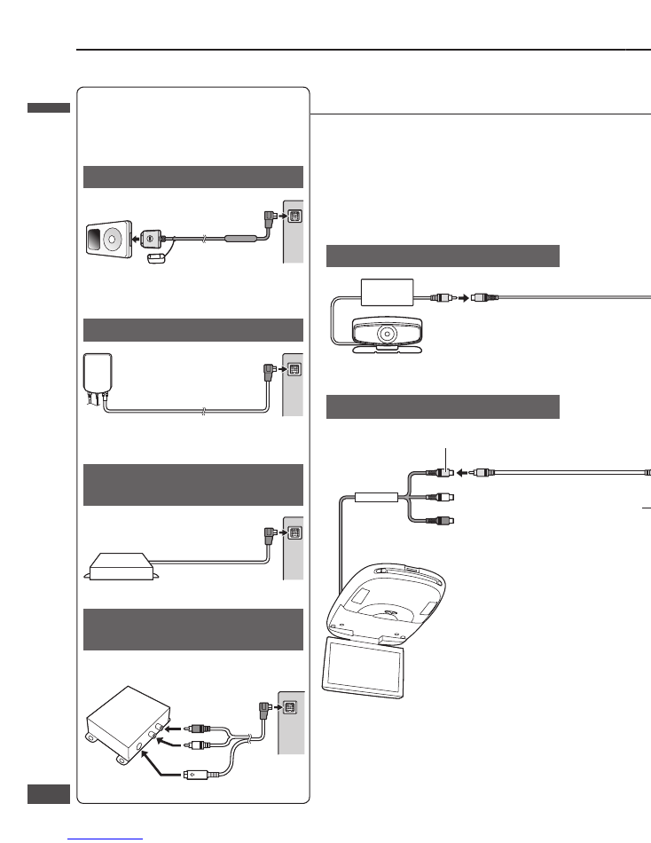
External unit connections
iPod
®
Hands-free kit (CY-BT100U)
SIRIUS Satellite Radio Tuner
(SIR-PAN1)
XM Satellite Radio Tuner
(XMD1000)
Video cassette recorder
Rear monitor (CY-VHD9401U)
Rear view camera
Direct cable for iPod
(CA-DC300U, option)
Also refer to the operating instructions for the connected devices.
CN-NVD905U (Rear)
RCA cord
iPod
Hands-Free Kit fearturing
Bluetooth
®
technology
(CY-BT100U, option)
SIRIUS Satellite Radio Tuner
(SIR-PAN1)
XM Satellite Radio Tuner
(XMD1000)
TV Tuner
(CY-TUN153U, option)
Video (Yellow) L (White) R (Red)
REMOTE IN (Black)
Video (Yellow)
Overhead 9
Widescreen Color LCD Monitor with
Built-in DVD Player
(CY-VHD9401U, option)
RCA cord
(supplied with CY-TUN153U)
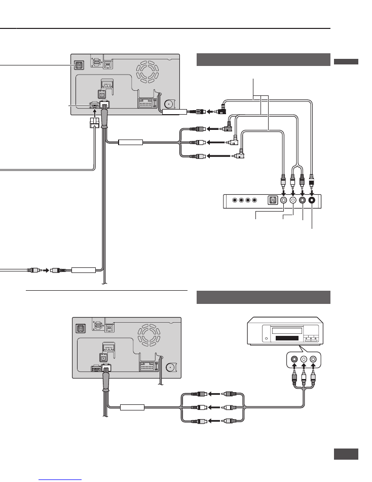
Rear View Camera
Rear view camera –
RCA conversion cable
Video input terminal
(AV-IN)
Video output terminal
(VIDEO-OUT)
R (Red)
Video (Yellow)
L (White)
REMOTE OUT
(Black)
Rear view camera
connector
Connecting to the System-up connector
The devices below can be connected.
Use an Expansion module (CY-EM100U, option) if
you need to connect two or more devices.
CN-NVD905U (Rear)
Video cassette recorder
TV tuner (CY-TUN153U)
R (Red)
Video (Yellow)
L (White)
RCA cord
Video input terminal
(AV-IN)
Digital Adapter Cable
(XMDPAN110)
R (Red)
L (White)
DIN Connector
English
English
12
13
13
12
VIDEO-OUT
AV-IN
VTR-IN
REMOTE-OUT
AV-IN
External unit connections
iPod
®
Hands-free kit (CY-BT100U)
SIRIUS Satellite Radio Tuner
(SIR-PAN1)
XM Satellite Radio Tuner
(XMD1000)
Video cassette recorder
Rear monitor (CY-VHD9401U)
Rear view camera
Direct cable for iPod
(CA-DC300U, option)
Also refer to the operating instructions for the connected devices.
CN-NVD905U (Rear)
RCA cord
iPod
Hands-Free Kit fearturing
Bluetooth
®
technology
(CY-BT100U, option)
SIRIUS Satellite Radio Tuner
(SIR-PAN1)
XM Satellite Radio Tuner
(XMD1000)
TV Tuner
(CY-TUN153U, option)
Video (Yellow) L (White) R (Red)
REMOTE IN (Black)
Video (Yellow)
Overhead 9
Widescreen Color LCD Monitor with
Built-in DVD Player
(CY-VHD9401U, option)
RCA cord
(supplied with CY-TUN153U)
Rear View Camera
Rear view camera –
RCA conversion cable
Video input terminal
(AV-IN)
Video output terminal
(VIDEO-OUT)
R (Red)
Video (Yellow)
L (White)
REMOTE OUT
(Black)
Rear view camera
connector
Connecting to the System-up connector
The devices below can be connected.
Use an Expansion module (CY-EM100U, option) if
you need to connect two or more devices.
CN-NVD905U (Rear)
Video cassette recorder
TV tuner (CY-TUN153U)
R (Red)
Video (Yellow)
L (White)
RCA cord
Video input terminal
(AV-IN)
Digital Adapter Cable
(XMDPAN110)
R (Red)
L (White)
DIN Connector
English
English
12
13
13
12
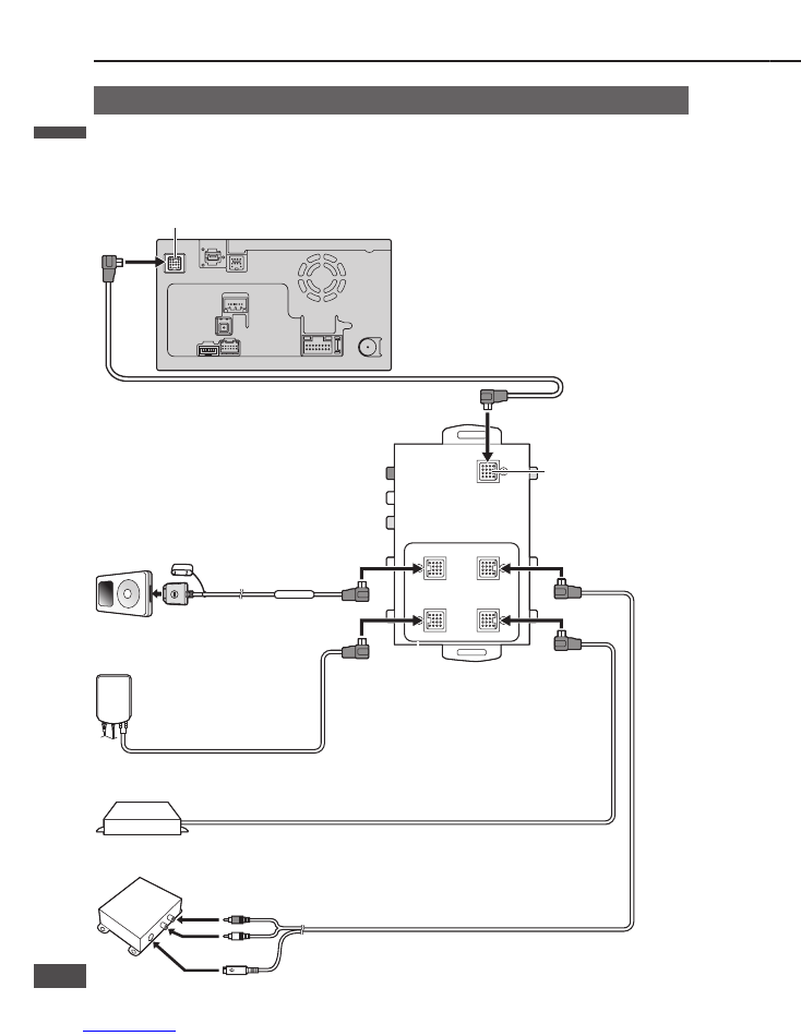
Connection with expansion module (CY-EM100U)
Hands-Free Kit featuring
Bluetooth
®
technology
(CY-BT100U, option)
iPod
Direct cable for iPod
(CA-DC300U, option)
SIRIUS Satellite Radio Tuner
(SIR-PAN1)
XM Satellite Radio Tuner
(XMD1000)
CN-NVD905U (Rear)
Expansion module
(CY-EM100U, option)
System-up connector
Head unit/Expansion module
connecting cable
(supplied with CY-EM100U)
System-up connector (Input)
System-up connector
(Output)
If you use an Expansion module (CY-EM100U, option), you will also be able to connect an iPod, hands-free kit,
SIRIUS Satellite Radio Tuner or XM Satellite Radio Tuner.
If multiple devices of the same type are connected at the same time, this unit will only recognize one of them.
(For example, if three iPods are connected, only one will be recognized.)
External unit connections
(continued)
Digital Adapter Cable
(XMDPAN110)
R (Red)
L (White)
DIN Connector
English
English
14
15
15
14

Panasonic Consumer
Electronics Company,
Division of Panasonic
Corporation of North America
One Panasonic Way, Secaucus,
New Jersey 07094
http://www.panasonic.com
Panasonic Puerto Rico, Inc.
Ave. 65 de Infanteria, Km. 9.5
San Gabriel Industrial Park,
Carolina, Puerto Rico 00985
http://www.panasonic.com
Panasonic Canada Inc.
5770 Ambler Drive,
Mississauga, Ontario
L4W 2T3
http://www.panasonic.ca
CN-NVD905U
System Up
Dual DIN in-dash HDD Mobile Navigation System with 7
Widescreen Color
LCD Monitor/DVD Receiver
Système de navigation embarqué à disque dur de format 2-DIN
avec récepteur DVD/moniteur couleur ACL grand écran de 7 po
Sistema de navegación portátil de doble DIN para tablero de mandos, con
disco duro y monitor LCD panorámico de 7
en color y receptor con DVD
CN-NVD905U
System Upgrade Guidebook
Guide pratique de mise à niveau de système
Guía de mejora del sistema
Read the “Safety information” presented in the Operating Instructions before
using this product.
This manual explains basic operations. Refer to the Operating Instructions for
detailed operation methods.
Avant d’utiliser le présent produit, veuillez lire les « informations sur la sécurité »
décrites dans le manuel d’instructions.
Le présent manuel décrit les opérations de base. Pour obtenir des informations
détaillées sur l’utilisation, consultez le manuel d’instructions.
Lea la “Información de seguridad” que aparece en las Instrucciones de
funcionamiento antes de utilizar este producto.
En este manual se explican operaciones básicas. Consulte los métodos de
funcionamiento detallados en las Instrucciones de funcionamiento.
© 2007 Matsushita Electric Industrial Co., Ltd. All Rights Reserved.
YEFM285973 F0107-1037
© 2007 Matsushita Electric Industrial Co., Ltd. Tous droits réservés.
Printed in Japan
Imprimé au Japon
Impreso en Japan