Full Text Searchable PDF User Manual
1300 538 598
www.trailparts.com.au
sales@trailparts.com.au
TRAILPARTS PRODUCT
HOW-TO GUIDE
4500KG
GVM
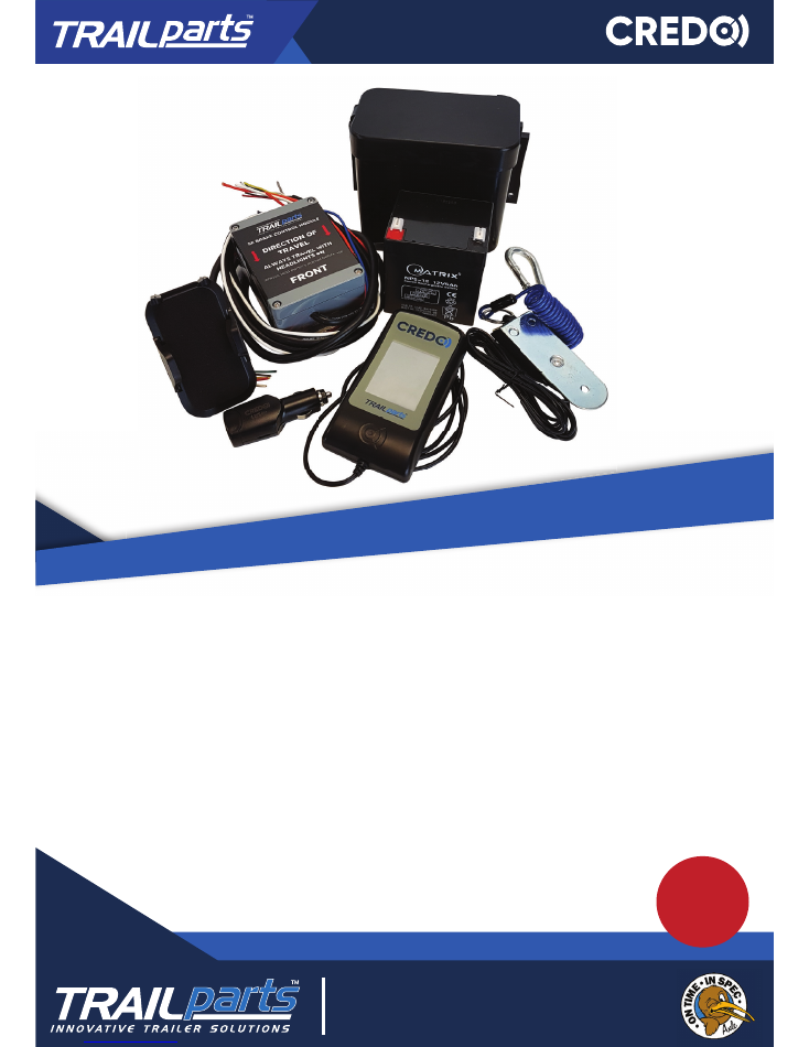
WIRING INSTRUCTIONS FOR
Trailparts
Credo Brake Control
to suit electric drum brakes
TM
TM
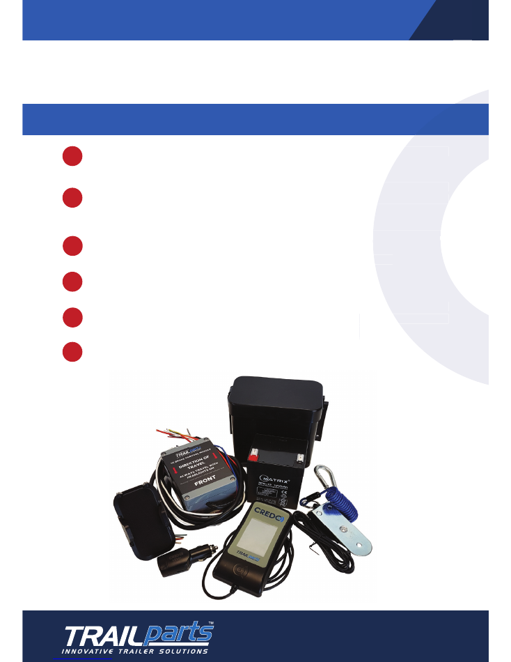
CREDO CAB CONTROLS
The Trailparts™ Credo™ Braking system meets Australian Design Rules 38
braking regula� ons and is legal for trailers up to 4500kg GVM when used according to
these instruc� ons.
2
1300 538 598
www.trailparts.com.au
sales@trailparts.com.au
TO OPERATE:
>
>
>
>
>
>
The in-cab controller must be connected at all � mes and located within easy
reach of the driver.
The vehicle park or head-lights must be switched on when towing the trailer. This
energizes the trailer side of the system and also will allow the trailer ba� eries to
charge.
Check the plug and socket of the trailer and tow vehicle are securely connected
and that the trailer ligh� ng func� ons all work correctly. A faulty or intermi� ent
ligh� ng connec� on could mean the brakes do not operate correctly.
Ensure the break away cable is securely fastened to the vehicle.
Test the emergency brake is working. First adjust the gain control se� ng to read
75%. Depress emergency stop bu� on fully, and begin to pull forwards while s� ll
holding the bu� on down. The trailer brakes should lock the wheels.
Do not use the emergency stop feature or breakaway func� on as a parking brake.
Test the emergency brake is working. First adjust the gain control se� ng to read
75%. Depress emergency stop bu� on fully, and begin to pull forwards while s� ll
holding the bu� on down. The trailer brakes should lock the wheels.
The in-cab controller must be connected at all � mes and located within easy
The vehicle park or head-lights must be switched on when towing the trailer. This
energizes the trailer side of the system and also will allow the trailer ba� eries to
Check the plug and socket of the trailer and tow vehicle are securely connected
and that the trailer ligh� ng func� ons all work correctly. A faulty or intermi� ent
ligh� ng connec� on could mean the brakes do not operate correctly.
Test the emergency brake is working. First adjust the gain control se� ng to read
75%. Depress emergency stop bu� on fully, and begin to pull forwards while s� ll
Do not use the emergency stop feature or breakaway func� on as a parking brake.
-
0
EMERGENCY
STOP
LESS
MORE
ADJ.
+
GAIN
SENS.
Z
z
P
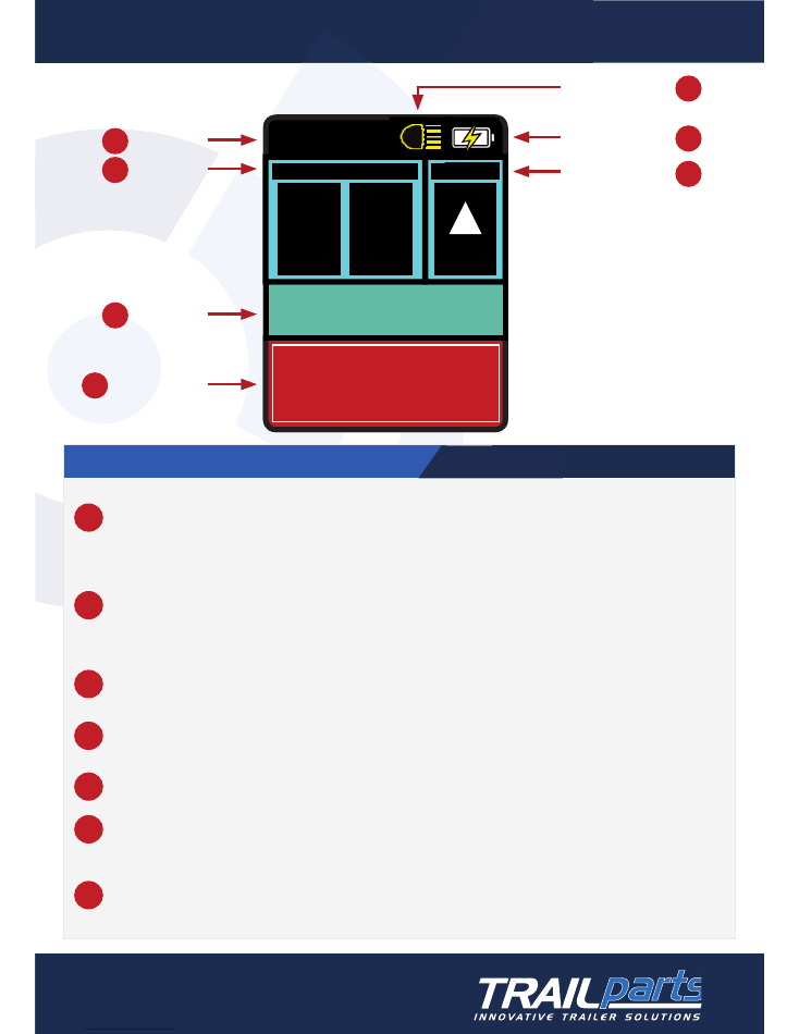
Screen sleep
Gain control
Braking level
Emergency brake
Tail-light indicator
Hand-piece ba� ery
Sensi� vity control
1
2
3
4
5
6
7
CREDO CAB CONTROLS
1
Screen Sleep Button
Press and hold for 5 seconds. Unit will beep 6 � mes and display sleep menu. When put to sleep while plugged into power,
tap screen to wake. If put to sleep while unplugged, unit will need to be plugged into power again to wake up.
2
Gain Control - Adjusting Gain Control:
Press either bu� on once to show current gain se� ng.
The plus bu� on will increase the maximum brake percentage, and the minus bu� on will decrease it. This should be set so
the vehicle will brake to a halt without the trailer wheels locking up. An eff ec� ve benchmark is to perform a brisk stop on
a straight fl at stretch of road from 30 kph. The vehicle trailer combina� on should halt without the trailer wheels locking.
Increase or decrease the gain se� ng un� l the trailer is braking at just under the lock up level. Ensure condi� ons are safe
around you before carrying out this procedure.
3
Braking Level
This number displays braking level during braking and gain and sensi� vity se� ngs.
4
Emergency Brake
When ac� vated, this will apply the trailer brakes at 75% of the current gain se� ng. This can be used to control trailer sway
situa� ons and stop the vehicle combina� on in an emergency.
5
Tail-light Indicator
Confi rms tail-lights are on. Shows red X if tail-lights not detected
6
Hand-piece Battery
Status of hand-piece ba� eries
7
Sensitivity Control
Press once to show current se� ng.
Controls determine how quickly and aggressively the brakes will ac� vate, with 1 being least and 5 the most aggressive.
Pressing this advances the se� ng from 1 up to 5 and then back to 1. Se� ng this to 3 provides mid-range braking. Decrease
se� ng to 2 or 1 if brakes come on too suddenly. Increase se� ng if braking ac� on seems too slow.
Credo Cab Controls
3
1300 538 598
www.trailparts.com.au
sales@trailparts.com.au
CREDO SCREEN CONTROLS AND WARNINGS
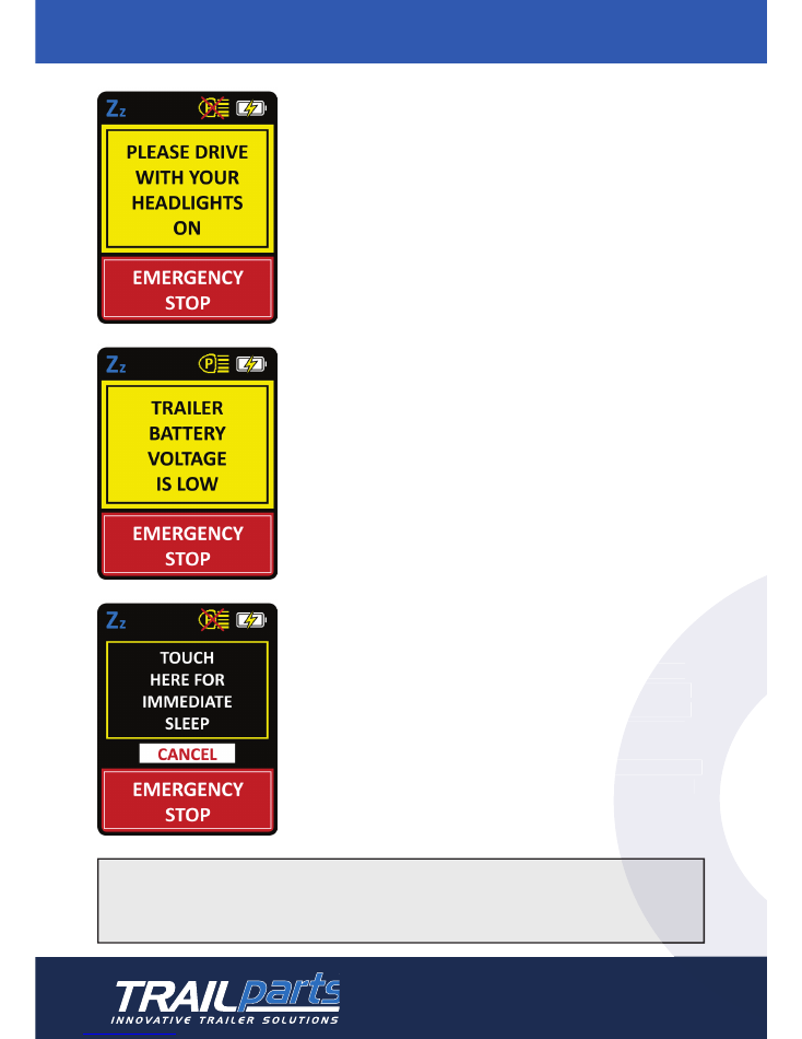
Headlights Warning
Will fl ash on screen with 4 beeps if headlights are not
on on the trailer or there is a loss of communica� on
between the trailer and cab modules. In the event of
communica� on loss, providing the headlamps are on
and the ligh� ng connec� on between the tow vehicle
and the trailer is not faulty the brakes will con� nue
to operate at the last se� ng. This should however be
inves� gated as soon as it is safe to stop.
Low Trailer Battery Warning
Will fl ash and beep 4 � mes each � me the brakes or
emergency brake are applied if the trailer ba� ery
voltage has dropped to an unsafe level, which would
result in the brakes not opera� ng correctly. This screen
will also display if the trailer ba� ery is disconnected.
Sleep Menu
Press and hold ‘Zz’ in the top le� corner of the screen
for 5 seconds. Credo unit will beep 6 � mes and display
sleep menu shown to the le� . Press the indicated area
of the screen to put the unit into sleep mode or press
cancel to return to the home screen.
When put to sleep while plugged into power, tap screen
to wake. If put to sleep while unplugged, unit will need
to be plugged into power again to wake up.
Note: Trailer module is compa� ble with 12 or 24 volt. Cab unit
is compa� ble with standard vehicle USB ports or 12 or 24 power
sockets providing a 12-24 volt USB adapter is used.
4
1300 538 598
www.trailparts.com.au
sales@trailparts.com.au
Press and hold ‘Zz’ in the top le� corner of the screen
for 5 seconds. Credo unit will beep 6 � mes and display
sleep menu shown to the le� . Press the indicated area
of the screen to put the unit into sleep mode or press
When put to sleep while plugged into power, tap screen
to wake. If put to sleep while unplugged, unit will need

CREDO INSTALLATION INSTRUCTIONS
5
1300 538 598
www.trailparts.com.au
sales@trailparts.com.au
>
Mount the Brake controller according to the moun� ng orienta� on instruc� ons
on page 7.
>
Wire the brake controller according to the instruc� ons on page 6.
>
It is important that trailers fi � ed with the Credo
TM
braking system are also fi � ed
with 12/24 volt LED lights, not LED or incandescent lights that are voltage specifi c
>
The controller is capable of running trailers with up to 6 wheels braked with
electric drum brakes.
>
The earth from the trailer brakes and the trailer ba� ery must only connect to
the brake controller output earths as shown in the diagram. They cannot be
connected to a common chassis earth.
>
Cable gauge should be of suffi cient size to avoid voltage drop. For electric
drum brakes a minimum of 15 amp cable should be used and a separate feed
should be run per two wheels that are fi � ed with brakes.
>
The trailer lights must only be connected to the 5 core ligh� ng output from the
controller and cannot bypass this directly to the trailer plug.
>
There is a spare orange wire and pink wire that are not used when installing on
a trailer fi � ed with electric drum brakes. These can be cut short and taped off .
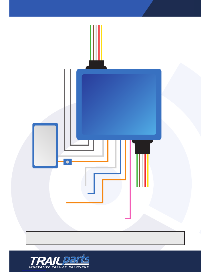
ELECTRIC DRUM WIRING DIAGRAM
6
1300 538 598
www.trailparts.com.au
sales@trailparts.com.au
Connect one grey to each side
of the breakaway switch
White
to Electric Drum Earth
Blue
to Electric Drum Positve
Orange
is not used
Green - Right Indicator
Brown - Tail light
White - Earth
Red - Stop light
Yellow - Left Indicator
Connect trailer lights to
5 core output
Batt
er
y C
onnections
Whit
e Negativ
e
Or
ang
e P
ositiv
e
One 5 Amp/hr
battery
Must be fitted
with battery
supplied.
Do not use
brake system
battery to
power any
other systems
There should be no more
than 2.5 metres of cable
between the controller and
the trailer plug to avoid
voltage drop.
30amp Fuse
Pink
not used
Wiring diagram above applies to SE Brake Controller with electric drums only
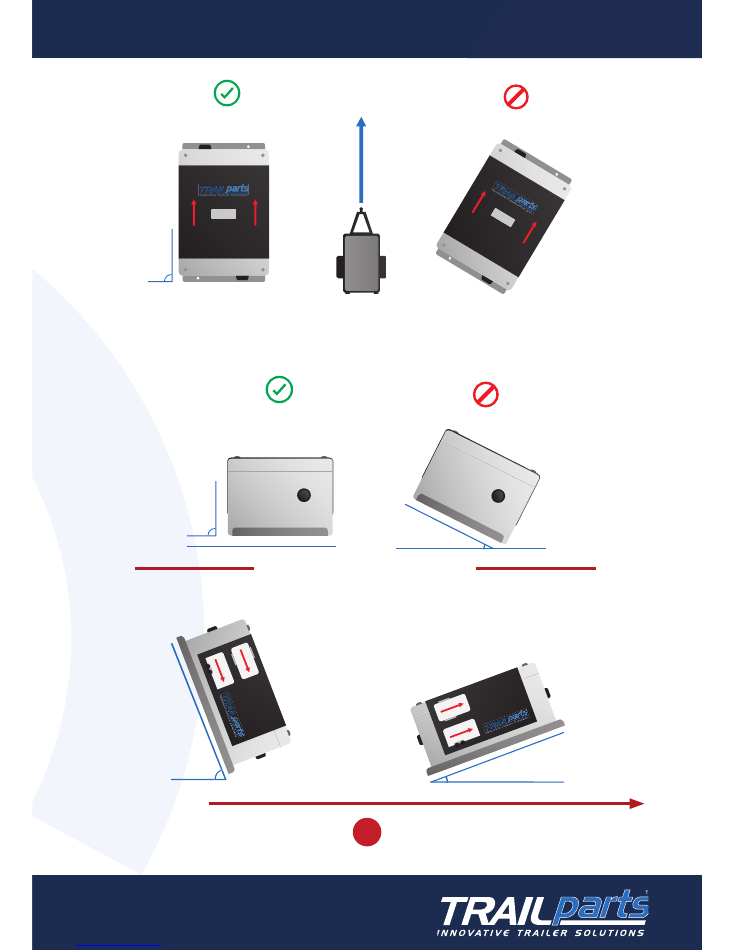
Direction of Travel
Must be mounted straight longitudinally, i.e. parallel to direction of travel
INCORRECT
CORRECT
90
o
FRONT
FRONT
Unit Must Be Level
Laterally
INCORRECT
CORRECT
90
o
SIDE
Direction of Travel
SIDE
Back can be up to
70 Degrees Up
Back can be up to
20 Degrees Down
20
o
70
o
OR
DIRECTION OF TRAVEL
Must be mounted straight longitudinally, i.e. parallel to the direc� on of travel
FRONT
FRONT
Unit Must Be Level
Laterally
INCORRECT
CORRECT
90
o
Unit must be level laterally
Direction of travel
Back can be up to 70 degrees up
Back can be up to 20 degrees down
OR
7
1300 538 598
www.trailparts.com.au
sales@trailparts.com.au
ON-TRAILER MODULE MOUNTING ORIENTATION

MAINTENANCE AND CHECKS
>
Check ba� ery is keeping well charged. A well charged ba� ery should be at
or above 13 volts. This is par� cularly important if the trailer is le� parked for
extended periods of � me. If the trailer is not used for extended periods the
ba� ery should be removed every 2 months and charged to ensure it does
not become damaged. This can happen if the ba� ery charge drops below
10.5 volts.
>
Check the trailer plug and vehicle socket to ensure they are not damaged and
they give a sound electrical connec� on. An intermi� ent or faulty connec� on
could mean the brakes do not func� on correctly.
>
If fi � ed with a hydraulic actuator make sure the fl uid level remains suffi cient.
The fl uid should be changed in line with general trailer service intervals.
>
If fi � ed with electric drums make sure they are kept properly adjusted and
that the magnets and linings are not excessively worn and are replaced in
line with general trailer service intervals.
OTHER INFORMATION
The trailer and cab parts of the controller are uniquely paired together by their serial
numbers.
The serial number is a 3 or 4 digit number and is located on the bo� om of the cab unit
and is stamped on the front of the trailer unit.
www.trailparts.com.au
1300 538 598
1300 538 598
www.trailparts.com.au
sales@trailparts.com.au
FOR MORE INFORMATION