Full Text Searchable PDF User Manual

VRS8 Quick Start
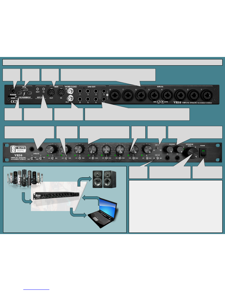
Connects to
PCIe card via
HDMI cable
MIDI I/O
Thunderbolt
ports
MIX LINK
Connects software mixers
of multiple units
WORD CLOCK I/O
LINE OUTS
1-2 Are Main Mix from Software Panel - Use for Speakers - controlled by MONITOR LEVEL knob
3-4 Source changes with MODE selection, see Software Panel - Mirrors send to headphones (Front Panel)
5-8 Are fed from DAW 5-8
INPUTS
1-8 Rear Panel Inputs feature combo jacks - XLR feeds mic input, TRS feeds Line Input
Phantom Switched via front panel
DI Inputs
Switch to INST, replaces MIC/LINE
Switch to LINE, MIC/LINE on rear panel active
PAD
Switches in 20dB
pad to Mic Input
GAIN CONTROL Channels 1-8
Shared gain control for Mic, Line and Inst levels
Signal/Clip
BiColor
LED
PHANTOM
Switches +48V
Channels 1-4
HEADPHONES
Phones A & B Level control and output jacks
Source changes with MODE selection, see Software
Panel - Mirrors send to Line Out 3-4 (Rear Panel)
POWER SWITCH
Ensure VRS8 is ON before
booting computer or
installing software
PHANTOM
Switches +48V
Channels 5-8
Use supplied
VRS8 PSU
15V DC 5A
15 VDC
MONITOR LEVEL
Controls Line Out 1-2 Trim
Use for Control Room Speakers, or set
at max when using monitor controller
VRS8 Hardware
Hardwired Chipset
Temperature Compensated TCXO Clocking
LLN (TM) Technology
DC Coupled Outputs for incredible low-end drive
VMS Mic Preamps
8 Mic/Line Inputs
2 FET DI Inputs
MIDI IO
Word Clock IO
MIX LINK IO
PCIe and Thunderbolt Connectivity
Phantom Power
Easy to use with and without a monitor controller
Discrete Headphone Amps
MIC/LINE INPUTS 1-8
THUNDERBOLT
CONNECTION
LINE OUT 1-2
BASIC SETUP

Software/Firmware Installation Instructions - THUNDERBOLT CONNECTIONS
1.
Download Driver
2.
Shut Down Computer
3.
Connect VRS8 to Computer via Thunderbolt Cable
4.
Connect VRS8 power supply and turn on unit
5.
Boot Computer
6.
Install Software/Firmware
7.
Restart Computer
8.
Open VRS8 Panel Software App
9.
Check Settings
10.
You’re Ready!
THE SOFTWARE PANEL
In the VRS8 Panel you can control Wordclock source and frequency, hardware
monitoring, DAW output level to your mix bus, and line output trims.
The VRS8 is designed to use DAW software monitoring with our analog
modeled plugins, but also provides a simple and easy to use mixer when
hardware monitoring is preferred.
There are some important features functions in the software panel that can
improve your workflow, we’ll go over them below.
TROUBLESHOOTING INFO
Here is the basic info we’ll ask for if you need service:
1.
VRS8 Serial Number
2.
Computer Make And Model, RAM
3.
Processor Make And Model
4.
DAW Version
5.
Buffer Settings (Session/DAW)
6.
Sample Rate (Session/DAW/VRS8 Panel)
7.
Cabling Terminations (Analog & Digital)
8.
PACE Driver Version
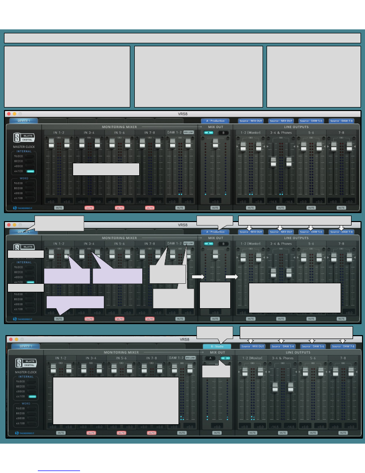
TABS list available devices -
select one to make changes
Internal Clock SRC
External Clock SRC
MUTE for normal use.
Unmute for Hardware Monitoring
LINK for stereo channels,
UNLINK for mono channels
(Hardware Monitoring)
Monitor Fader to MIX OUT
(Hardware Monitoring)
MIX LINK replaces
DAW return with MIX
LINK IN (Rear Panel)
DAW 1-2 Return
(Unit 2 is 9-10, unit
3 is 17-18, etc.)
MIX OUT FADER
Source is
monitoring
mixer
(incl. DAW 1-2)
OUTPUT MIXER SOURCES
These tabs show you where the output is fed from
HARDWARE OUTPUT TRIMS
These faders trim the HARDWARE LINE OUTS.
1-2 is controlled by the MONITOR LEVEL knob.
3-4 feeds PHONES on front panel & Line Out 3-4
The triangle marks UNITY GAIN +4 output
3dB extra headroom/gain available ABOVE that!
MODE SELECTION
MODE toggled to
STUDIO
OUTPUT MIXER SOURCES
Note that in STUDIO MODE, 3-4 & Phones are fed DAW 3-4
This is what the panel looks like. Below
are descriptions of the features.
STUDIO and PRODUCTION MODES
PRODUCTION MODE is default, and feeds the Line Out 3-4 and Phones with
your MIX OUT, which includes DAW 1-2. Use Line Out 3-4 for an external
headphone amp, mix deck, or processing chain.
STUDIO MODE feeds the Line Out 3-4 and Phones with DAW 3-4. Use when
you want a headphone mix different from your main mix, or when using an
external monitor controller or headphone system.
VRS8 Quick Start
MODE Toggle
Switches