Full Text Searchable PDF User Manual
Midwest Industries, Inc.
Ida Grove, IA 51445
800.859.3028
www.shorelandr.com
0003441
Page 1
®
SLB34BLW
Table of Contents:
Page
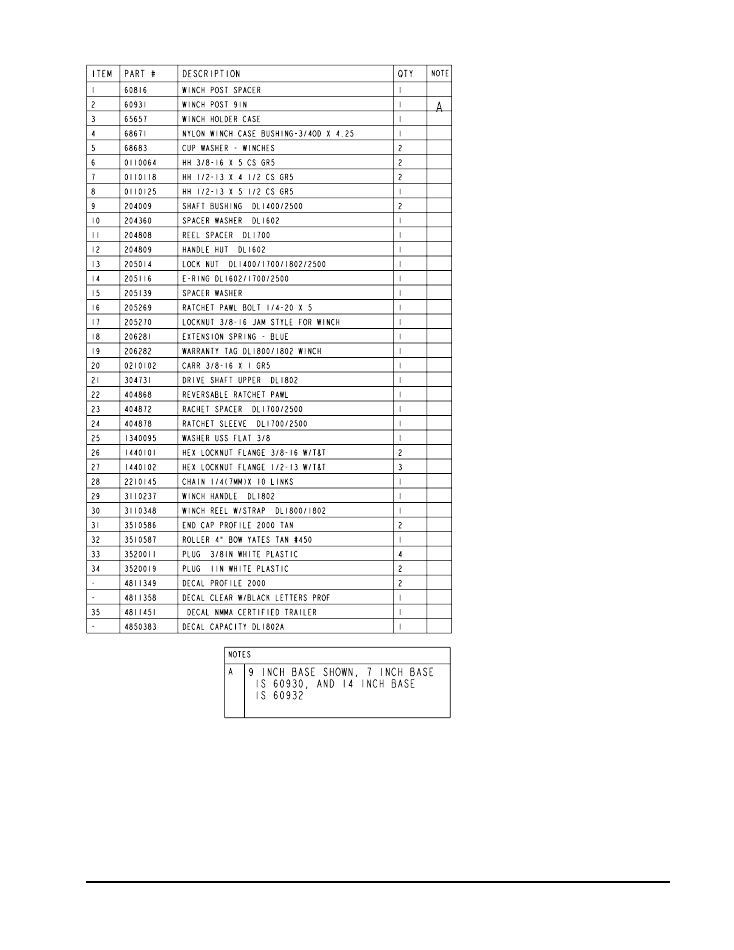
Frame Drawing & Bill of Materials ................................2-3
Bunk Assembly Instructions .........................................3
Tongue & Safety Chain Dwg/BOM. ..............................4-5
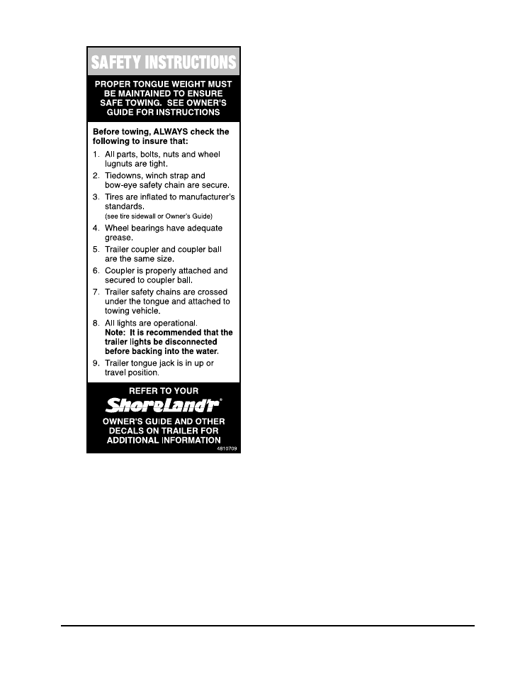
Safety Instructions ........................................................5
Tongue Assembly Instructions ......................................5
White Ground Wire Installation Instructions .................5
Safety Chain Assembly Instructions .............................5
Brake Line Installation Instructions ...............................5
Profile 2000
Winch Dwg/BOM/Assy Instr. ...................6-7
Chassis Drawing & Bill of Materials ..............................8-9
Tire Size & Carrying Capacity Chart .............................9
Spring Assembly Instructions .......................................9
Axle Assembly Instructions ...........................................9
One Axle Brake Installation ..........................................9-10
Tire & Wheel Assembly ................................................10
Trailer Adjustments .......................................................10
Axle Adjustments ..........................................................10
Rear Support System ...................................................10
Bunks ...........................................................................10
Front Bunk Support ......................................................10
Winch Post Adjustments ...............................................10
SLB34BLW Bundles Required:
4300269 ST205/75R15D Denman Tire/TS Dir Rim ... 2
(or)
4300268 ST205/75R15D Denman Tire/Galv Dir Rim . 2
68224
Brake Box w/Hardware ................................ 1
69082
Literature Bag - Trailers - Brakes ................ 1
80248-- Frame Bundle - 2X4W B34BLW ................. 1
66996-- Tongue Assembly 55”, W/UFP Actuator ...... 1
ShoreLand’r
offers their product line in either galvanized or
painted finish. When ordering parts it is important that you
specify the finish or color you have on your product. The five
(5) digit number along with a two (2) digit space _ _, note the
parts which can be purchased with various finishes. When
ordering these items use the five (5) digit number along with
a two (2) digit suffix for the proper finish.
00 .........Galvanized
01 .........Arctic White
03 .........Black
33 .........Galvanized w/Black Plastic Parts
Midwest Industries, Inc.
Ida Grove, IA 51445
800.859.3028
www.shorelandr.com
0003441
Page 2

Midwest Industries, Inc.
Ida Grove, IA 51445
800.859.3028
www.shorelandr.com
0003441
Page 3
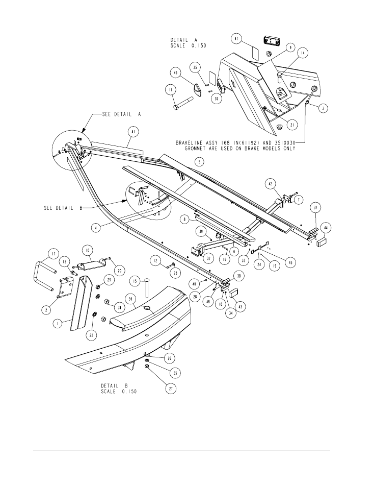
FINAL ASSEMBLY INSTRUCTIONS
Remove the hardware bag from the frame, remove parts
and sort by size.
B-SERIES BUNK ASSEMBLY
Locate the two 2 x 6 bunk assemblies. Note that the bunk
mounting brackets are assembled to the bunks at the fac-
tory. Place the end with the two brackets towards the rear of
the trailer. Place the assembly on the equiload bunk arm and
secure by placing a 3/8” x 1” hex bolt through the bracket on
the bunk and the ear on the end of the equiload arm. Secure
in place using a 3/8” lock nut. Repeat on the other end of the
arm. (See Diagram A).
Place the other end of the bunk in the bracket installed on the
front cross member. Note that this bracket is not attached to
the bunk because the trailer can be adjusted to two different
lengths. Once the proper position for the rear crossmember
is determined, the front of the bunk can now be attached to
the bracket using two- No. 10 x 1-1/4” self tapping screws as
shown in Detail B.
The 3/8” x 1” bolts attaching the bunks to the equiload arms
and front bunk bracket can be tightened but not over tight-
ened.
Midwest Industries, Inc.
Ida Grove, IA 51445
800.859.3028
www.shorelandr.com
0003441
Page 4
Midwest Industries, Inc.
Ida Grove, IA 51445
800.859.3028
www.shorelandr.com
0003441
Page 5
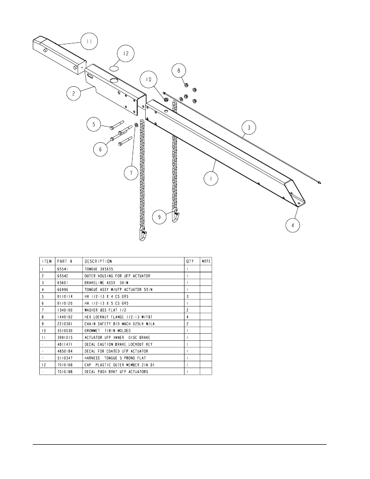
TONGUE
The tongue is shipped separate of the frame. Locate the
appropriate tongue and install by sliding it in the front of the
tongue channel.
Line the holes in the tongue with the holes in the tongue
channel. Install the 1/2” x 4” hex bolt in the front cross hole
and secure with a 1/2” lock nut.
Remove the wire harness from the rear of the tongue. Place
the wire harness and the brake line through the hole pro-
vided in the tongue cover plate. See Detail A in Diagram A.
Secure the tongue cover plate in position with the same
1/2” x 1-1/2” hex bolt that secures the back on the tongue to
the tongue channel of the frame. Secure with 1/2” lock nut.
Tighten both bolts just installed.
Plug the tongue wire harness ends into the frame harnesses
by matching colors and ends. Push the extra wire provided
either into the rear of the tongue or else remove the grom-
met in the side frame and place the extra wire in the side
frame. Replace grommet just removed.
WHITE GROUND WIRE INSTALLATION
Place the self-tapping screw provided through the round
metal ring on the white ground wire of the tongue harness
located at the rear of the tongue. Attach the ground wire to
the main frame by driving the screw in the hole provided
next to the tongue channel of the frame. This will assure a
positive ground for the lighting.
SAFETY CHAINS
Locate the 1/2” x 5” hex bolt. Slip the bolt through a 1/2” at
washer, then place through the last link of one of the safety
chains. Slide through actuator housing and tongue. Slide
other safety chain over bolt and add a 1/2” flat washer. Se-
cure with a 1/2” flange lock nut. See Diagram B.
Assembly is complete.
BRAKE LINE
Locate the brass brake line coupling. Remove the plastic cap
and thread the brake line coming out the rear of the tongue
into one end of the coupling. Bend the line in a smooth grad-
ual radius being careful not to kink the line. Bend so it can be
mated to the brake line from the side frame. Once aligned,
thread the side frame brake line into the other end of the
coupling. Tighten both lines into the coupling.
Midwest Industries, Inc.
Ida Grove, IA 51445
800.859.3028
www.shorelandr.com
0003441
Page 6
Midwest Industries, Inc.
Ida Grove, IA 51445
800.859.3028
www.shorelandr.com
0003441
Page 7
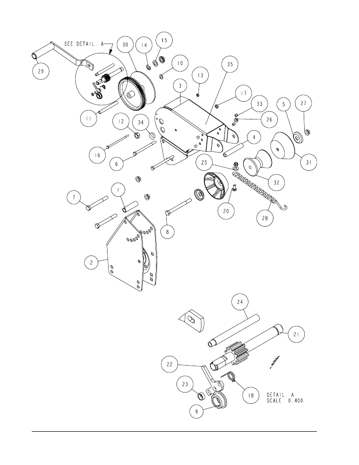
WINCH POST ASSEMBLY
The height that the bow eye is placed in
your boat will determine the length of
winch post required. Once this is deter-
mined, attach the winch base to the tongue
with three 1/2” x 4” carriage bolts and lock
nuts.
Align the holes in the
Profile 2000
mount-
ing channel with the holes in the top of the
winch base. Attach the front of the winch
head mounting channel to the base by
placing a 1/2” x 4-1/2” hex bolt through the
hole closest to the front of the winch base.
Secure with a lock nut. Do not tighten.
Note that the winch head can now be ro-
tated either up or down. Identify the cor-
rect hole combination to use to position the
bow eye roller just above the bow eye of
your boat. When determined, secure in this
position by placing the bushing as shown in
Diagram C inside the winch base so it aligns
with the hole just identified for the proper
adjustment. Insert another 1/2” x 4-1/2” hex
bolt through the determined mounting hole
in the mounting channel and winch base
making sure the bolt passes through the
bushing as well. Secure with a 1/2” lock nut.
Tighten all bolts.
Midwest Industries, Inc.
Ida Grove, IA 51445
800.859.3028
www.shorelandr.com
0003441
Page 8
Diagram D
Midwest Industries, Inc.
Ida Grove, IA 51445
800.859.3028
www.shorelandr.com
0003441
Page 9
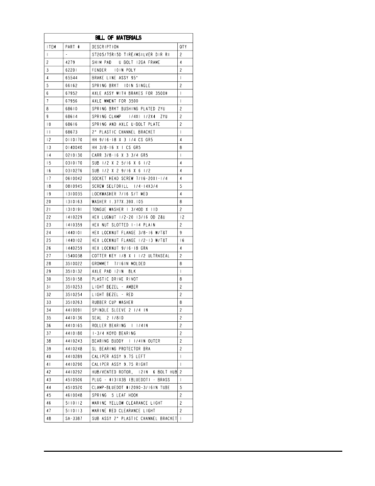
Tire Size and Carrying Capacity Chart
Tire Size
....................... ST205/75R 15-D
GVWR
.......................... 4240 lb.
Carrying Capacity
....... 3400 lb.
Axle
.............................. Disc Brakes
Refer to the tire side wall for correct tire pressure.
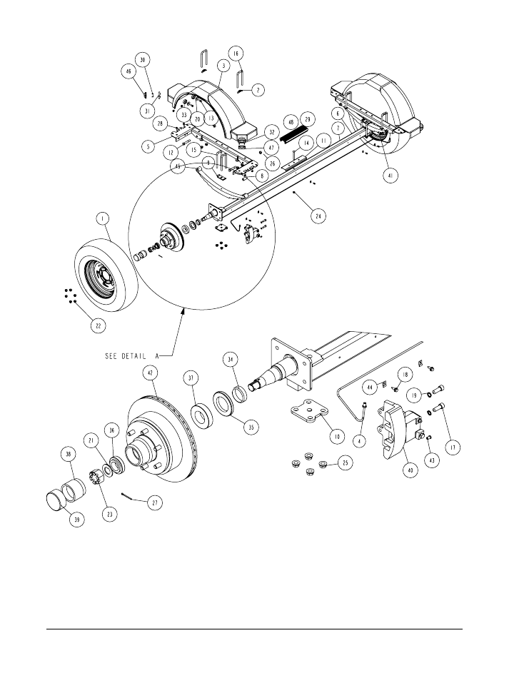
SPRINGS
Position the axle so it is properly aligned with the trailer and
the brake calipers are located on the back side of the axle.
(See Diagram D).
Place the springs on the top side of the spring pads welded
to the axle. (See chassis Diagram D). Note that the hook
end of the spring must be mounted to the rear of the trailer.
Place a spring clamp on the top center of the spring as
shown. Next place the 1/2” x 6-1/2” U-bolts down over the
top of the spring clamp, spring and axle as shown.
Place the spring and axle U-bolt plate onto the ends of the
two U-bolts just installed. Secure in place with 1/2” lock nuts.
Thread onto the U-bolts but do not tighten securely until the
complete unit is in position on the trailer. Repeat on the other
spring.
AXLE
Place one of the spring bracket bushings into the rear of the
spring bracket and secure with a 9/16” x 3 1/4” hex bolt and
hex lock nut.Repeat in other spring bracket.
Position the axle under the frame, then hook the loop end of
the spring around the bushings just installed. Note that if the
axle is positioned too low when trying to hook, the loops will
not hook around the bushings.
Raise the front of the springs up so they align with the front
hole of the spring bracket. Secure in place with 9/16” x 3-
1/4” hex bolts and lock nuts.
Tighten all axle U-bolts and spring bolts not tightened at this
time.
ONE AXLE BRAKE INSTALLATION
Cut the tape securing the brake line hose to the axle. Re-
move the brass plug from the port in the brass block on the
right brake caliper. Thread in the male end of the brake hose
and tighten to 6-8 ft. lb. or else 72-96 in. lb. of torque.
DO NOT OVER TIGHTEN
. Over tightening will cause the
brass block to crack and then leak.
Place the other end of the hose through the hole in the brake
line clip bracket and secure with the U-shaped hose clip pro-
vided.

Midwest Industries, Inc.
Ida Grove, IA 51445
800.859.3028
www.shorelandr.com
0003441
Page 10
Remove the plastic cap from the end of the frame brake line
coming out of the side frame.
Uncoil the brake line so that it reaches the end of the hose
just attached to the brake line clip bracket. Thread the brake
line fitting into the brake line
hose. Tighten.
NOTE:
The axle has brake fluid installed in the calipers and
the axle line when it is assembled at the factory. This is done
to protect the inner parts of the brake system during ship-
ping and storage. The complete brake system including the
axle
MUST
be re-bled to ensure that all air has been re-
moved from the brake system.For bleeding instructions see
the
UFP Brake Bleeding Manual
or else the
ShoreLand’r
Disc Brake Manual
.
Fill the actuator reservoir with brake fluid and bleed the line
per the instructions in the
Brake Manual.
TIRE & WHEEL ASSEMBLY
Mount the tire and wheel assemblies using the 1/2” fine
threaded tapered lug nuts provided. Tighten to 85-95 ft./lb.
torque using the rotation pattern as shown in the
Shore-
Landr’s Owners Manual
.
Re-torque the lug nuts after 50 miles driving and then peri-
odically thereafter.
TRAILER ADJUSTMENTS
The adjustment of the trailer to your boat is very important
not only for the trailer, but also the boat. Failure to do so
may lead to potential failure or damage to either the trailer
or boat.
Adjust as follows:
AXLE ADJUSTMENT
The amount of tongue weight on your trailer can be adjusted
as follows:
To lower the tongue weight, adjust the axle assembly for-
ward. To increase the tongue weight, adjust the axle back-
ward. The distance that the axle assembly has to be moved
will vary because it is directly related to the weight and cen-
ter of gravity of the boat placed on it.
Best towing is achieved when the tongue weight is 5-7% of
the total gross load of the complete unit.
Note
: Wire harnesses and brake line lines (if equipped with
brakes) will need care when moving the axle assembly.
REAR SUPPORT SYSTEM
Place the boat on the trailer so that the transom is located at
the rear of the support system. The center of the rear rollers
on the roller rack should be approximately 4” from the tran-
som. This gives you maximum support on the transom.
The rear cross member is adjustable forward or backward to
allow the trailer to be adjusted to various length boats on all
models except the XLW. This is accomplished by removing
the pivot bolt on holds each end of the rear pivot to the side
frame. Reposition the rear pivot arm into the other hole posi-
tion predrilled in the side frame.
Reattach the rear pivot to the side frame with the bolts just
removed. Tighten.
The wire harness for the three-light identification light must
be repositioned where it comes from the side frame to the
rear pivot to eliminate slack, and sagging of the wiring.
BUNKS
Make sure the bunks are positioned far enough apart to give
your boat as much stability as possible while transporting.
Position the bunks so they are located just the outside of a
strake that your boat may have. This will help center your
boat and assist when loading. The bunks need be adjusted
up high enough to keep the keel from resting on the center
pads. A minimum of one to two inches clearance is desir-
able.
FRONT BUNK SUPPORT
The front bunks should be adjusted either in or out so that
the bunk will continue to run just to the outside of the strake
of the boat. Adjust the bunks up so that there is approxi-
mately 1-2 inches clearance between the keel of the boat
and the center cross member pad.
WINCH POST
Once all other adjustments are complete the winch post can
be adjusted. Slide the winch post base backward on the
tongue until the bow roller comes in contact with the boat.
The bow roller needs to be positioned directly above the
boat bow eye to prevent your boat from moving forward in
the event of a sudden stop. It can be moved up or down by
removing the back bolt that mounts the winch head to the
base. When this bolt is removed, the head can be rotated
up or down to reach the desired height required to fit your
boat. Once in this position, align the closest pair of holes in
the brackets and reinsert the bolt just removed. Tighten.
Attach the winch strap and crank winch tight. Attach the bow
eye safety chain into the bow eye of the boat as well. This is
just another level of protection to keep your boat and trailer
together as one unit.
Adjustments are now complete. Double check your boat for
fit. If the desired fit has been achieved, tighten all fasteners
that may have either been left loose or have been loosened
to do the adjusting.
Note
: All nuts and bolts must be tightened before towing.
The law requires that the white ground wire on both the
tongue wire harness and vehicle harness be properly
grounded to respective trailer and vehicle frames.
Recheck all fasteners on the complete trailer to make sure
they are all tight and ready for towing. All fasteners should
be periodically checked before towing.
See your
ShoreLand’r Owner’s Guide
for further technical
information regarding your trailer and its components.