Full Text Searchable PDF User Manual
Required Items:
➤
SEL-3355-2 Computer
➤
Power cable(s)
➤
Monitor with DisplayPort or DVI cable
➤
USB keyboard
➤
USB mouse
➤
Phillips
®
screwdriver
➤
1/8-inch slotted screwdriver
Optional Items:
➤
Ethernet cable
➤
USB storage device
➤
SEL Computing Products Literature and
Software DVD
➤
USB CD/DVD Drive
Getting Started With the SEL-3355-2
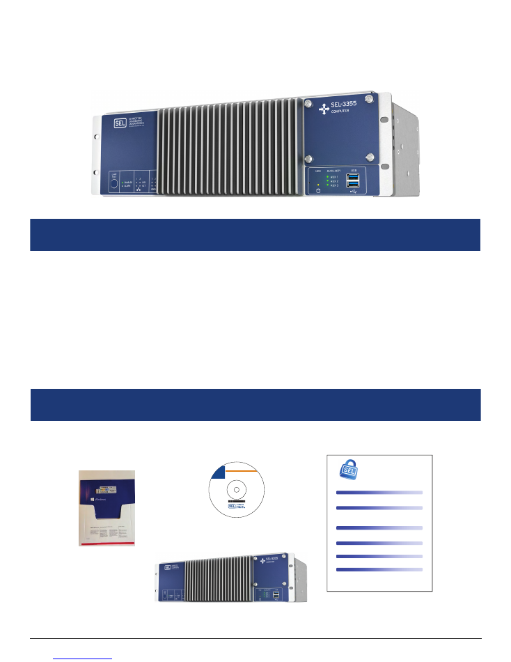
Verify that the following items are included:
What Is Included
SEL-3355-2
SEL Computing Products
Literature and Software DVD
Computing Platform
Security Tips
C
OMPUTING
P
LATFORM
S
ECURITY
T
IPS
SEL understands the importance of security for SEL computing plaorms. Please take a moment to review
some ps to keep your computing plaorm secure. Your company computer security policy should take
priority over any of these suggesons.
Unlike protecve relays, compung plaorms need to have the operang system safely shut down before
removing power. This shutdown will increase the reliability of your computing plaorm. Computing
plaorms with the enhanced write filter (EWF) need to have
any changes saved before powering the system
down or those changes will not be preserved.
SEL uses a Naonal Instute of Standards and Technology (NIST) guide
(hp://csrc.nist.gov/itsec/guidance_WinXP.html) in securing Microso® Windows® XP-based computing
plaorms. Most guides recommend disabling ports and services that are not in use. Consider a benchmark
such as the Center for Internet Security (hp://benchmarks.cisecurity.org) when creang your own security
baseline. Use your baseline to assess computing plaorm changes and measure risk. Consider using the
items below as part of your baseline.
SEL computing plaorms are malware free from the factory, but will not stay that way without proper
precauons. Anvirus and whitelisng applicaons help prevent infecons. Anvirus applicaons, while
relavely easy to set up, require frequent updates. Whitelisng applicaons must be carefully configured,
but require fewer updates and have lile impact on performance.
USB and network shares increase your risk of malware infecons and data leakage. To minimize risk, be
careful about what you plug into your computing plaorm. If you must use USB or network shares, then
define a safe process for USB and network share use.
On most computing plaorms the firewall is enabled by default. This is the preferred seng and provides
another layer of security for your computing plaorm. Ensure that the firewall is enabled, and minimize the
number and scope of excepons.
Malicious soware exploits rights and services on the computing plaorm. Only enable services that are
absolutely necessary. Improve computing plaorm protecon by reserving administrave accounts for
specific maintenance and installaon tasks.
S
ECURE
Y
OUR
S
YSTEM AND
S
ET A
B
ASELINE
L
IMIT
S
ERVICES AND
R
IGHTS
U
SE THE
F
IREWALL
R
ESTRICT
E
NTRY
P
OINTS
P
ROTECT
A
GAINST
M
ALWARE
R
ECOGNIZE
T
HAT AN
SEL
C
OMPUTING
P
LATFORM
I
S
N
OT A
P
ROTECTIVE
R
ELAY
Contents:
• SEL-3355 Literature
• SEL-3360 Literature
• SEL-3390S8 Instruction Manual
• SEL-3390E4 Instruction Manual
• SEL-9331 Instruction Manual
• CIS Benchmarks
• Drivers
• Software developed by the
open-source community
Note: A PDF viewer is required.
Installation:
1. Insert the DVD into the drive.
2. If Windows autorun is
enabled, the Contents.html
file will load automatically.
3. If Windows autorun is not
enabled, access files via
Windows Explorer.
Literature and Software DVD
SEL Computing Products
2350 NE Hopkins Court • Pullman, WA 99163 U.S.A.
Tel: +1.509.332.1890 • Fax: +1.509.332.7990
www.selinc.com • info@selinc.com
© 2015 Schweitzer Engineering Laboratories, Inc.
All rights reserved
PM3355-01-DVD/UDVD00160
20150721
Operating System DVD
(if ordered with
Windows Server)
What You Will Need
Getting Started With the SEL-3355-2
Date Code 20180212
2
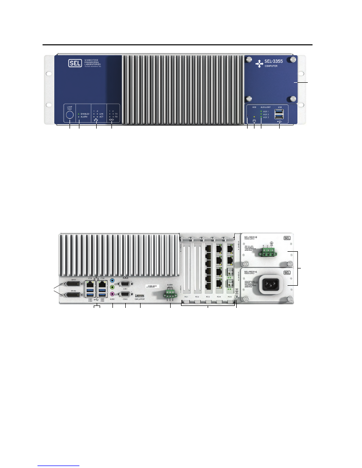
Product Overview
q
LAMP TEST
Button. Press and hold to test front-panel LEDs. Can be programmed to be an on/off or reset button.
w
ENABLED
and
ALARM
LEDs provide operational status. A green
ENABLED
LED indicates normal operation.
The
ALARM
LED illuminates red when a nonoptimal system condition exists.
e
ETHERNET
Status Indicators. Link (
LNK
) indicates that the port is connected, and activity (
ACT
) indicates when data
are being transmitted and received.
r
SERIAL
Status Indicators. Transmit (
TX
) and receive (
RX
) LEDs indicate activity on serial ports.
t
PINHOLE
Button. Provides reset and power functions; requires a pushpin to prevent accidental use.
y
HDD
Activity Indicator. Illuminates when SATA drives are accessed.
u
AUXILIARY
Status Indicators. Three programmable, bicolor LEDs for your custom application.
i
USB
Ports. Two easily accessible ports to connect USB 3.1 peripherals.
o
SATA
Drive Bay. Removable cover plate enables easy access to SATA drives from the front panel.
q
DVI-D
. Connect digital monitors by using native DVI or an HDMI adapter.
w
ETH1
and
ETH2
. Onboard independent Gigabit Ethernet interfaces.
e
USB
Ports. Connect as many as four USB 3.1 peripherals at the rear panel.
r
AUDIO
Ports. Line Input (blue), Line Output (green), and Microphone Input (pink).
t
COM1
and
COM2
. Standard EIA-232 serial ports with configurable +5 Vdc power on Pin 1.
y
DISPLAYPORT
. Connect new digital monitors supporting the DisplayPort interface.
u
ALARM
. The Form C alarm contact output can be wired either normally closed or normally open.
i
PCI
Expansion Slots. Install SEL or third-party PCI or PCI Express expansion cards for additional network, serial,
or other application-specific I/O.
o
Earth Ground
Terminal Screw. The earth ground connection for the SEL-3355-2.
a
POWER
Supply Modules. The rated input voltage is clearly marked on the chassis near the terminals.
q
w
e
r
y
t
u
i
o
a
q
y
t
r
e
w
i
u
o
Date Code 20180212
Getting Started With the SEL-3355-2
3
Introduction
The SEL-3355-2 is a rack-mountable rugged computer. It is designed to operate in extreme environments and
carries the Schweitzer Engineering Laboratories ten-year worldwide warranty. The SEL-3355-2 has the following
features:
➤
Intel
®
Xeon E3 processor
➤
Four 2.5" SATA drive bay with hot-swap and RAID capabilities
➤
Six USB 3.1 ports
➤
Five PCI expansion card slots
➤
Two Gigabit Ethernet interfaces
➤
Dual, redundant power supplies with hot-swap
➤
Watchdog timer for automatic recovery from system lockup
➤
Three display interfaces supporting three simultaneous independent displays
➤
HD Audio inputs and output
Procedure Overview
The following is a list of the primary tasks described in this guide:
➤
Unpack and Setup on page 3
➤
First Boot on page 8
➤
Install Expansion Cards on page 12
➤
Install Operating System on page 13
➤
Install Applications on page 14
➤
Create a Backup With SEL BaRT on page 14
➤
Long-Term Storage on page 15
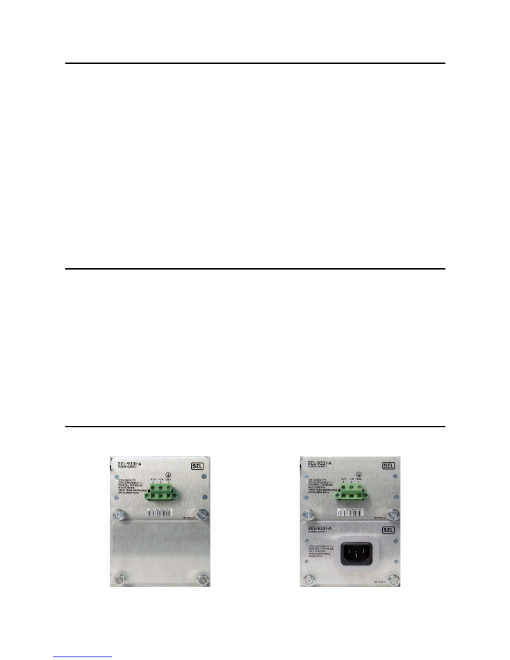
Unpack and Setup
Verify that the correct number and type of power supplies are installed (see
Figure 1
and
Figure 2
).
Figure 1
Single Power Supply
Figure 2
Dual Power Supplies
Getting Started With the SEL-3355-2
Date Code 20180212
4
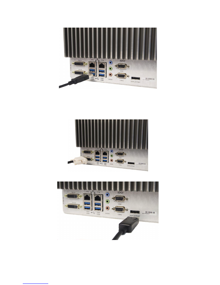
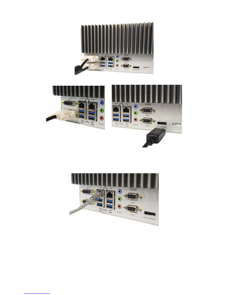
Step 1. Connect the keyboard and mouse to any of the USB ports as shown in
Figure 3
.
Figure 3
USB Connection
Step 2. Connect the monitor(s) to the video ports.
The SEL-3355-2 will support as many as three monitors.
Figure 4
–
Figure 5
show single monitor
connections.
Figure 4
Single DVI Connector to DVI-D
Figure 5
Single DisplayPort Connection
Figure 6
and
Figure 7
show dual monitor connections.
Date Code 20180212
Getting Started With the SEL-3355-2
5
Figure 6
Dual DVI Connections
Figure 7
DVI-D With DisplayPort
Step 3. If you need network access, connect an Ethernet cable from a switch or router to either
ETH1
or
ETH2
as shown in
Figure 8
. Each port has two status indicator LEDs. The right LED illuminates yellow to
indicate a link or connection is present. The left LED flashes green during data transfer.
Figure 8
Ethernet Network Connection
Advanced features like Preboot eXecution Environment (PXE), Wake-on-LAN (WOL), or Intel
®
Active Management Technology (AMT) use
ETH1
. See the
SEL-3355-2 Instruction Manual
for more
details.
Step 4. If you need a serial port connection, the SEL-3355-2 has two onboard serial ports with the
following specifications:
➤
Data rates: 300 to 115200
➤
Data bits: 5, 6, 7, and 8
Getting Started With the SEL-3355-2
Date Code 20180212
6
➤
Parity: None, Even, Odd, Mark, and Space
➤
Stop Bits: 1 or 2
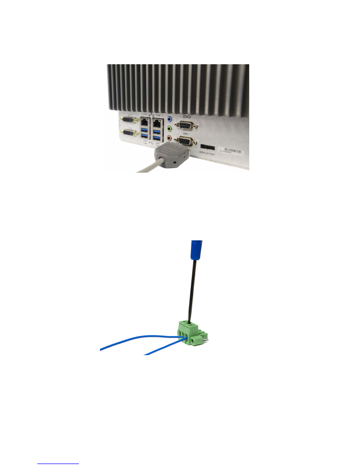
You can connect to serial ports
COM 1
or
COM 2
as shown in
Figure 9
.
Figure 9
Serial Port Connections
If more serial ports are needed, you can use the SEL-3390S8 expansion card to expand the serial
capabilities of the SEL-3355-2.
Step 5. If you connect the Alarm contact, connect wires to the compression terminal block by using a
1/8-inch slotted screwdriver as shown in
Figure 10
.
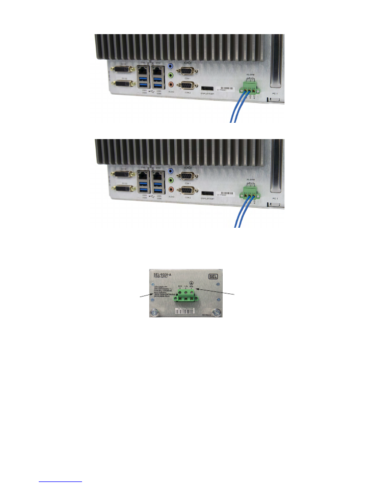
The Alarm contact can be wired to accommodate normally closed or normally open protection
schemes as shown in
Figure 11
and
Figure 12
.
Figure 10
Wiring Compression Terminal Block
Date Code 20180212
Getting Started With the SEL-3355-2
7
Figure 11
Normally Closed
Figure 12
Normally Open
Step 6. The SEL-3355-2 can be powered by a single power supply, and has the option of being powered by
two redundant power supplies. Look at the labeling on the rear panel of each power supply to
determine the rated input voltage (see
Figure 13
).
Figure 13
Wiring Guide and Supply Ratings
Use a 1/8-inch slotted screwdriver to wire the power cable to the supplied compression terminal
block, as indicated by the wiring guide on the back of the power supply (see
Figure 13
).
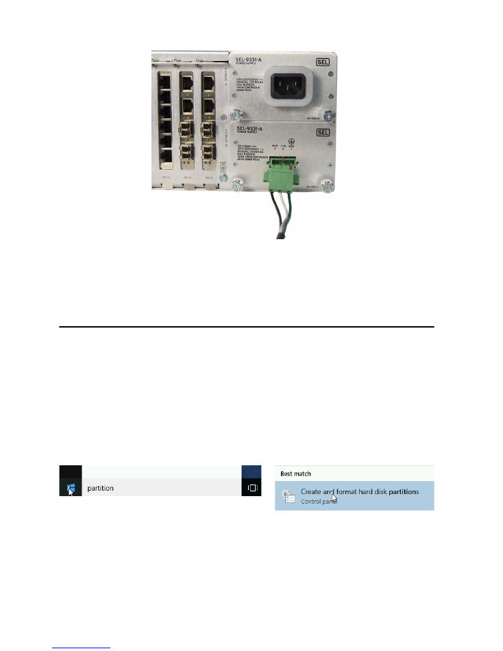
Step 7. Attach the compression terminal block to the power supply as shown in
Figure 14
.
Note:
Removing the compression terminal block from the back of the computer will disconnect
power from it. Do not remove it unless you intend to turn off the device.
Wiring
Guide
Supply
Ratings
Getting Started With the SEL-3355-2
Date Code 20180212
8
Figure 14
Attach Compression Terminal Block to Power Supply
Step 8. If you ordered dual power supplies, connect the second power supply the same way as the first.
Note:
The second power supply can have different input requirements than the first (see
Figure 13
for location of supply ratings).
First Boot
For SEL-3355-2 With Microsoft Windows
Upon initial startup, the SEL-3355-2 may require you to perform some initial steps to configure Microsoft
®
Windows
®
operating system, such as creating a user account and password. After completing the Windows
configuration, you should check the system to verify that all SATA drives are installed and correctly configured,
and all hardware and software packages are installed.
Hard Drive(s)
Perform the following steps to verify that the correct number of SATA drives is installed:
Step 1. Click the
Start
button, type
partition
in the box, and then select
Create and format hard disk
partitions
.
Step 2. The User Account Control may ask for confirmation that you understand the program being
launched can be used to make changes to the computer. Click
Yes
, or provide your account
credentials, to indicate that it is acceptable to proceed.
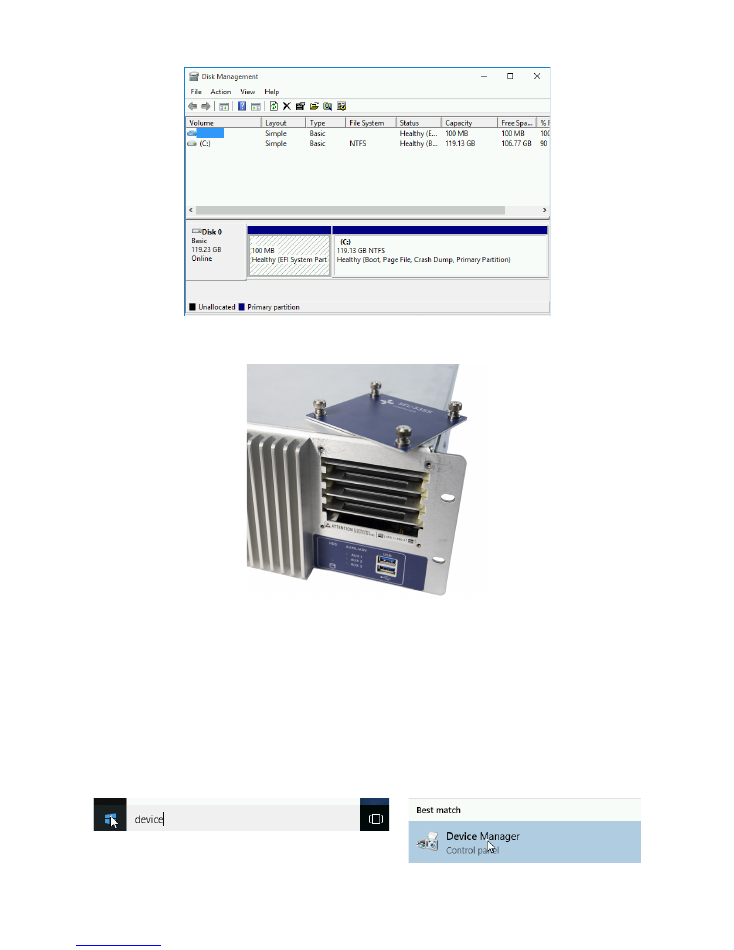
Step 3. In the lower pane of the
Disk Management
window, verify that there is a disk listed (e.g., Disk 0,
Disk 1, etc.) for each SATA drive ordered with the system.
Date Code 20180212
Getting Started With the SEL-3355-2
9
Step 4. If any of the SATA drives that were ordered with the computer are not displayed, open the SATA
drive bay on the front panel of the SEL-3355-2 and verify that they are installed.
Step 5. If all drives are installed, turn off the SEL-3355-2. Then pull out and reinstall each drive one at a
time, ensuring that they are firmly inserted.
Step 6. Restore power to the SEL-3355-2 and verify that all drives are now present in the
Disk
Management
application.
If any of the drives are not present after performing this step, contact your customer service
representative for further assistance.
Hardware
Perform the following steps to verify that all the hardware is correctly installed in the SEL-3355-2:
Step 1. Click the
Start
button, type
device
in the box, and then select
Device Manager
.
Getting Started With the SEL-3355-2
Date Code 20180212
10
Step 2. The User Account Control may ask for confirmation that you understand the program being
launched can be used to make changes to the computer. Click Yes, or provide your account
credentials, to indicate that it is acceptable to proceed.
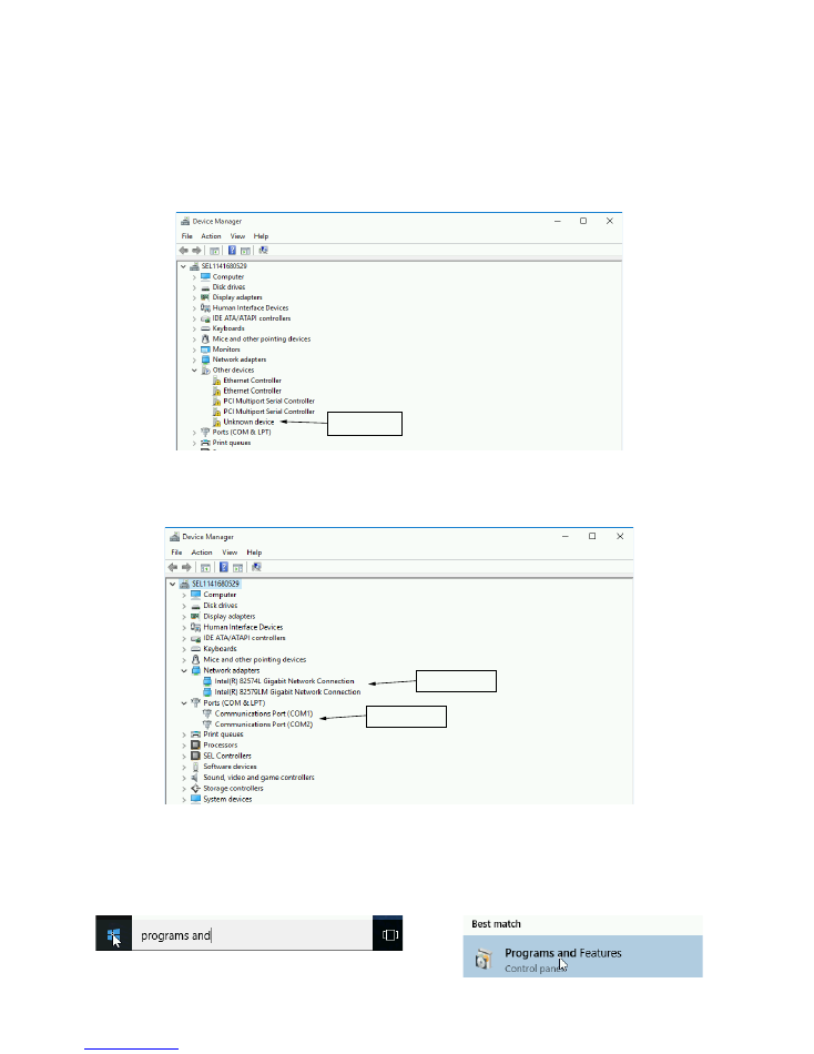
Step 3. In the
Device Manager
window, verify that there are no missing device drivers by opening
Other
devices
, if it is present, and ensuring that there are no
Unknown device
listings. If there are
unknown devices listed, then there are device drivers that are not installed. All drivers that are
nondefault Microsoft drivers are included on the Literature and Software DVD. For assistance in
identifying which driver to install, contact your SEL customer service representative.
Step 4. Click on
Network adapters
and
Ports (COM & LPT)
to verify that the correct number of serial
and Ethernet ports are listed.
Note:
The number of ports will depend on ordering options.
Software
Perform the following steps to verify that all the software packages ordered with the SEL-3355-2 have been installed:
Step 1. Click the
Start
button, type
programs and features
in the box, then select
Programs and
Features
.
Missing Driver
Ethernet Ports
Serial Ports
Date Code 20180212
Getting Started With the SEL-3355-2
11
Step 2. The User Account Control may ask for confirmation that you understand the program being
launched can be used to make changes to the computer. Click Yes, or provide your account
credentials, to indicate that it is acceptable to proceed.
Step 3. Verify that all the software packages ordered with the computer are listed.
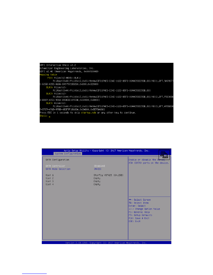
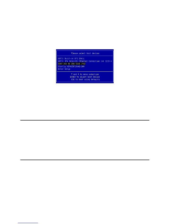
For an SEL-3355-2 With No Operating System
If the SEL-3355-2 does not have a bootable operating system installed, it will boot to an EFI Shell similar to the
following figure.
Perform the following steps to verify that all the SATA drives are installed:
Step 1. Restart the SEL-3355-2 and press
<F2>
to enter BIOS setup.
Step 2. In the
System Configuration
menu, select
SATA Configuration
and then verify that the expected
SATA drives are listed in Slots 1–4.
Step 3. Perform
Step 4 on page 9
through
Step 6 on page 9
if any of the expected SATA drives are not
listed.
Getting Started With the SEL-3355-2
Date Code 20180212
12
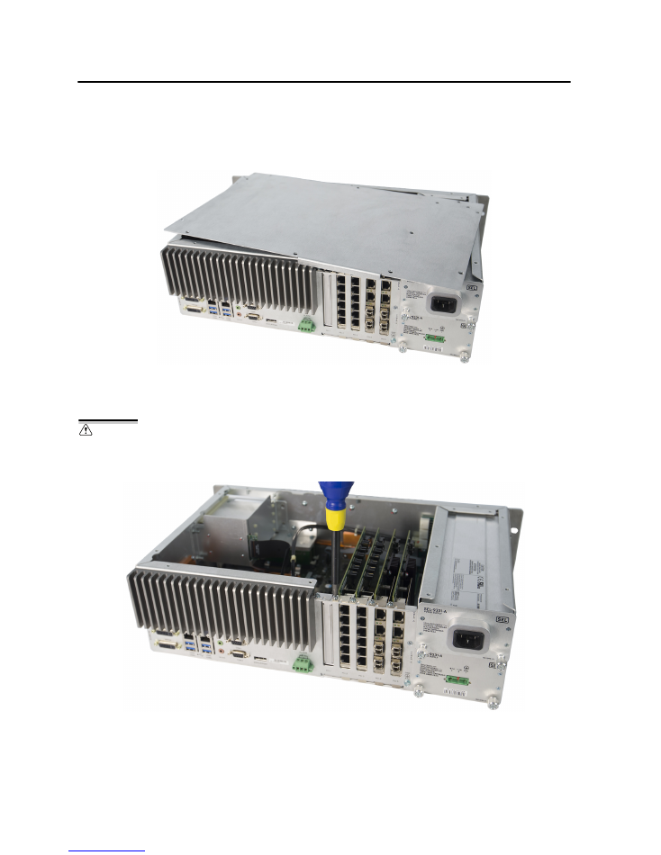
Install Expansion Cards
Note:
Perform the steps in this section if you have an expansion card to install in the SEL-3355-2.
The SEL-3355-2 has expansion card slots to accommodate PCI Express (PCIe) and legacy PCI cards. To
install additional PCIe/PCI devices, perform the following steps:
Step 1. Remove power to the SEL-3355-2 and remove the top cover.
Step 2. Remove the cover plate from the slot where the expansion card is to be installed.
Note:
Expansion cards can be installed in any slot large enough to accommodate them.
Step 3. Ensure that the expansion card is completely inserted into the slot before securing it to the case of
the SEL-3355-2 with the retaining screw.
CAUTION
Equipment components are sensitive to electrostatic discharge (ESD). Undetectable permanent damage can result if you do not use proper ESD
procedures. Ground yourself, your work surface, and this equipment before removing any cover from this equipment. If your facility is not
equipped to work with these components, contact SEL about returning this device and related SEL equipment for service.

Date Code 20180212
Getting Started With the SEL-3355-2
13
Step 4. Replace the SEL-3355-2 top cover.
Refer to the documentation included with the expansion card for any additional instructions, such as software or
driver installation.
Install Operating System
Note:
Perform the steps in this section if you want to install an operating system on the SEL-3355-2.
Before you can install the operating system, you must disable the watchdog timer. Perform the following steps to
disable the watchdog timer:
Step 1. Enter the BIOS setup utility by pressing
F2
immediately after applying power to the system.
Step 2. Navigate to the
Boot Features
subform on the
Main
tab.
Step 3. Select
System Watchdog
and press
<Enter>
.
Step 4. Select
Disabled
, press
F10
to save settings, and then select
Yes
.
Getting Started With the SEL-3355-2
Date Code 20180212
14
Most operating systems are distributed on DVD media. To install the operating system from a DVD, perform the
following steps:
Step 1. Attach the external DVD-ROM drive to the USB port on the SEL-3355-2.
Step 2. Insert the installation DVD into the DVD-ROM drive and start/restart the SEL-3355-2. The
SEL-3355-2 should start from the DVD automatically.
If the SEL-3355-2 fails to start from the DVD, restart the system and immediately press
<F5>
to
load the
Boot Menu
. Verify that the DVD-ROM drive is listed as a boot option. If it is present,
select it using the up and down keys and press
<Enter>
.
Note:
If the DVD-ROM drive fails to boot when selected, then the DVD is not bootable. If the DVD
reader is not listed among the boot devices, then the reader is not compatible with the SEL-3355-2
firmware.
When the operating system installation is complete, install any SEL System Monitor (SysMon) and SEL drivers
that are available for the installed operating system. Refer to the Literature and Software DVD for more
information about which operating systems have SysMon and driver packages.
Install Applications
Note:
Perform the steps in this section if you have additional applications to install in the SEL-3355-2.
If the application is distributed on CD or DVD, you will need an external USB DVD-ROM drive.
If the installer is a file or set of files, the simplest method of transferring these files to the SEL-3355-2 is to use a
USB drive. Take precautions to ensure that the SEL-3355-2 is not infected with malware during the process of
transferring files. Scanning the USB drive with an up-to-date antivirus package prior to plugging the drive into the
SEL-3355-2 is highly recommended.
Create a Backup With SEL BaRT
It is highly recommended to create a backup of the SEL-3355-2 once the system is fully configured. A copy of the
SEL Backup and Recovery Tool (SEL BaRT) is included on the
SEL
Computing Products Literature and Software
DVD. SEL BaRT provides an easy method of making a backup of an entire disk and storing it in a single file on a
USB storage device.
For further information, please refer to the SEL BaRT application guide on the
SEL
Computing Products
Literature and Software DVD.

Date Code 20180212
Getting Started With the SEL-3355-2
15
Long-Term Storage
The
SEL-3355-2
has a battery to maintain its internal real-time clock. If the unit is not plugged in for a long
period of time (e.g., in excess of a year) this battery may become depleted. It is recommended that the battery
be replaced if the
SEL-3355-2
has been in storage for longer than one year.
Technical Support
We appreciate your interest in SEL products and services. If you have questions or comments, please contact us at:
Schweitzer Engineering Laboratories, Inc.
2350 NE Hopkins Court
Pullman, WA 99163-5603 U.S.A.
Tel: +1.509.338.3838
Fax: +1.509.332.7990
Internet: selinc.com/support
Email: info@selinc.com

Getting Started With the SEL-3355-2
Date Code 20180212
16
© 2018 by Schweitzer Engineering Laboratories, Inc. All rights reserved. All trademarks are the property of their respective holders. SEL products appearing in this document may
be covered by U.S. and Foreign patents. The information in this document is provided for informational use only and is subject to change without notice.
*PLS3355-04*