Full Text Searchable PDF User Manual
BEDIENUNG UND INSTALLATION
OPERATING AND INSTALLATION
UTILISATION ET INSTALLATION
GEBRUIK EN INSTALLATIE
OBSŁUGA I INSTALACJA
OBSLUHA A INSTALACE
HASZN
Á
LATI
É
S TELEP
Í
T
É
SI
Ú
TMUTAT
Ó
UPRAVLJANJE IN NAMESTITEV
Elektronisch gesteuerter Durchlauferhitzer | Electronically controlled
instantaneous water heater | Chauffe-eau instantan
é à gestion électronique
| Elektronisch gestuurde elektrische doorstromer | Elektronicznie sterowany
przepływowy ogrzewacz wody | Elektronicky
řízený průtokový ohřívač | Elektromos
vez
érlésű átfolyós vízmelegítő | Elektronsko krmiljen pretočni grelnik
» DHB 18 STi
» DHB 21 STi
» DHB 24 STi
» DHB 27 STi

18
| DHB STi
www.stiebel-eltron.com
CoNTeNTS | SPeCIAL INforMATIoN
SPECIAL INFORMATION
OPERATION
1.
General information ��������������������������������������� 19
1.1
Safety instructions ���������������������������������������������� 19
1.2
Other symbols in this documentation ���������������������� 19
1.3
Units of measurement ����������������������������������������� 19
2.
Safety �������������������������������������������������������� 19
2.1
Intended use ����������������������������������������������������� 19
2.2
General safety instructions ����������������������������������� 19
2.3
Test symbols ����������������������������������������������������� 19
3.
Appliance description ������������������������������������� 20
4.
Operation ��������������������������������������������������� 20
4.1
Recommended settings ��������������������������������������� 20
5.
Cleaning, care and maintenance ������������������������� 20
6.
Troubleshooting �������������������������������������������� 20
INSTALLATION
7.
Safety �������������������������������������������������������� 21
7.1
General safety instructions ����������������������������������� 21
7.2
Instructions, standards and regulations ������������������� 21
8.
Appliance description ������������������������������������� 21
8.1
Standard delivery ����������������������������������������������� 21
8.2
Accessories ������������������������������������������������������� 21
9.
Preparations ������������������������������������������������ 22
9.1
Installation site �������������������������������������������������� 22
9.2
Water installation ����������������������������������������������� 22
10.
Installation �������������������������������������������������� 23
10.1 Standard installation ������������������������������������������� 23
11.
Commissioning ��������������������������������������������� 25
11.1 Initial start-up ��������������������������������������������������� 25
11.2 Recommissioning ����������������������������������������������� 25
12.
Shutdown ��������������������������������������������������� 25
13.
Alternative installation options ��������������������������� 25
13.1 Electrical connection from above on unfinished walls �� 25
13.2 Electrical connection on finished walls �������������������� 26
13.3 Large conductor cross-section for electrical
connection from below ���������������������������������������� 26
13.4 Connecting a load shedding relay ��������������������������� 26
13.5 Water installation on finished walls ������������������������ 26
13.6 Water installation on finished walls with brazing /
compression fitting ��������������������������������������������� 27
13.7 Water installation on finished walls; fitting the
appliance cover ������������������������������������������������� 27
13.8 Installation of lower back panel with threaded fittings
on finished walls ������������������������������������������������ 27
13.9 Wall mounting bracket when replacing an appliance ��� 27
13.10 Installation with offset tiles ����������������������������������� 27
13.11 Pivoting appliance cover �������������������������������������� 28
14.
Troubleshooting �������������������������������������������� 29
15.
Maintenance ������������������������������������������������ 30
16.
Specification ������������������������������������������������ 30
16.1 Dimensions and connections ��������������������������������� 30
16.2 Wiring diagram ������������������������������������������������� 30
16.3 DHW output ������������������������������������������������������ 31
16.4 Application areas / conversion table ����������������������� 31
16.5 Pressure drop ��������������������������������������������������� 31
16.6 Fault conditions ������������������������������������������������� 31
16.7 Country-specific approvals and certifications: Germany 31
16.8 Details on energy consumption ������������������������������ 32
16.9 Data table �������������������������������������������������������� 32
GUARANTEE
ENVIRONMENT AND RECYCLING
SPeCIAL INforMATIoN
- The appliance may be used by children aged 8
and older and persons with reduced physical,
sensory or mental capabilities or a lack of ex-
perience and know-how, provided that they are
supervised or they have been instructed on how
to use the appliance safely and have understood
the resulting risks. Children must never play with
the appliance. Children must never clean the ap-
pliance or perform user maintenance unless they
are supervised.
- Risk of burns: the tap can reach temperatures in
excess of 55 °C.
- Ensure the appliance can be separated from the
power supply by an isolator that disconnects all
poles with at least 3 mm contact separation.
- Secure the appliance as described in chapter "In-
stallation / Installation".
- Observe the maximum permissible pressure (see
chapter "Installation / Specification / Data table").
- Drain the appliance as described in chapter "In-
stallation / Maintenance / Draining the appliance".
oPerATIoN
general information
www.stiebel-eltron.com
DHB STi |
19
EN
GL
ISH
oPerATIoN
1. General information
The chapters "Special Information" and "Operation" are intended
for both the user and qualified contractors.
The chapter "Installation" is intended for qualified contractors.
Note
Read these instructions carefully before using the appli-
ance and retain them for future reference.
Pass on the instructions to any new user where appro-
priate.
1.1 Safety instructions
1.1.1 Structure of safety instructions
!
KEYWORD Type of risk
Here, possible consequences are listed that may result
from failure to observe the safety instructions.
f
f
Steps to prevent the risk are listed.
1.1.2 Symbols, type of risk
Symbol
Type of risk
Injury
Electrocution
Burns
(burns, scalding)
1.1.3 Keywords
KeYworD
Meaning
DANGER
Failure to observe this information will result in serious
injury or death.
WARNING
Failure to observe this information may result in serious
injury or death.
CAUTION
Failure to observe this information may result in non-seri-
ous or minor injury.
1.2 Other symbols in this documentation
Note
General information is identified by the adjacent symbol.
f
f
Read these texts carefully.
Symbol
Meaning
Material losses
(appliance damage, consequential losses and environmen-
tal pollution)
Appliance disposal
f
f
This symbol indicates that you have to do something. The ac-
tion you need to take is described step by step.
1.3 Units of measurement
Note
All measurements are given in mm unless stated oth-
erwise.
2. Safety
2.1 Intended use
The appliance is intended for heating domestic hot water and can
supply one or more draw-off points.
This appliance is intended for domestic use. It can be used safely
by untrained persons. The appliance can also be used in a non-do-
mestic environment, e.g. in a small business, as long as it is used
in the same way.
Any other use beyond that described shall be deemed inappropri-
ate. Observation of these instructions and of instructions for any
accessories used is also part of the correct use of this appliance.
2.2 General safety instructions
CAUTION Burns
During operation, the tap can reach temperatures in ex-
cess of 55 °C.
There is a risk of scalding at outlet temperatures in ex-
cess of 43 °C.
!
WARNING Injury
The appliance may be used by children aged 8 and older
and persons with reduced physical, sensory or mental
capabilities or a lack of experience and know-how, pro-
vided that they are supervised or they have been in-
structed on how to use the appliance safely and have
understood the resulting risks. Children must never play
with the appliance. Children must never clean the ap-
pliance or perform user maintenance unless they are
supervised.
!
Material losses
The user should protect the appliance and its tap against
frost.
2.3 Test symbols
See type plate on the appliance.
!
!
oPerATIoN
Appliance description
20
| DHB STi
www.stiebel-eltron.com
3. Appliance description
You can adjust the DHW outlet temperature via the temperature
selector. From a flow rate of approx. 3 l/min and above, the control
unit regulates the correct heating output, subject to the tempera-
ture setting and cold water temperature.
Heating system
The bare wire heating system has a pressure-tested plastic casing.
The heating system is suitable for (both) soft and hard water and
is largely resistant to scale build-up. This heating system ensures
rapid and efficient DHW availability.
Note
The appliance is equipped with an air detector that large-
ly prevents damage to the heating system. If, during op-
eration, air is drawn into the appliance, the appliance
shuts down for one minute, thereby protecting the heat-
ing system.
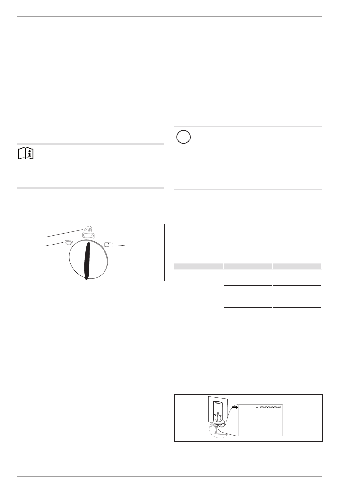
4. Operation
The DHW outlet temperature can be adjusted in 3 stages.
26
�0
2�
02
�0
95
1
1
2
3
1 Hand wash basin (approx. 35 °C)
2 Shower / bath (approx. 45 °C)
3 Kitchen sink (approx. 55 °C)
f
f
Turn the temperature selector to the required position.
Should the outlet temperature fail to reach the required level with
the tap fully open and the temperature selector set to maximum,
then more water is flowing through the appliance than can be
heated by the heating element.
f
f
Reduce the flow rate at the tap.
4.1 Recommended settings
Thermostatic valve
If you operate the appliance with a thermostatic valve, we rec-
ommend that you set the temperature on the appliance to the
maximum level (kitchen sink). You can then select the required
temperature using the thermostatic valve.
Following an interruption of the water supply
!
Material losses
To ensure that the bare wire heating system is not dam-
aged following an interruption to the water supply, the
appliance must be restarted in the following sequence.
f
f
Disconnect the appliance from the power supply by
removing the fuses/tripping the MCBs.
f
f
Open the tap for one minute until the appliance and
its upstream cold water inlet line are free of air.
f
f
Switch the mains power back ON again.
5. Cleaning, care and maintenance
f
f
Never use abrasive or corrosive cleaning agents. A damp
cloth is sufficient for cleaning the appliance.
f
f
Check the taps regularly. Limescale deposits at the tap out-
lets can be removed using commercially available descaling
agents.
6. Troubleshooting
Problem
Cause
remedy
The appliance will not
start despite the DHW
valve being fully open.
There is no power.
Check the fuses/MCBs in
your fuse box/distribu-
tion panel.
The aerator in the tap
or the shower head is
scaled up or contami-
nated.
Clean and/or descale the
aerator or shower head.
The water supply has
been interrupted.
Vent the appliance and
the cold water supply line
(see chapter "Operation /
Recommended settings /
Following an interruption
to the water supply").
Whilst hot water is being
drawn off, initially cold
water flows for a short
period.
The air sensor detects air
in the water and briefly
switches the heater off.
The appliance restarts
automatically after
1 minute.
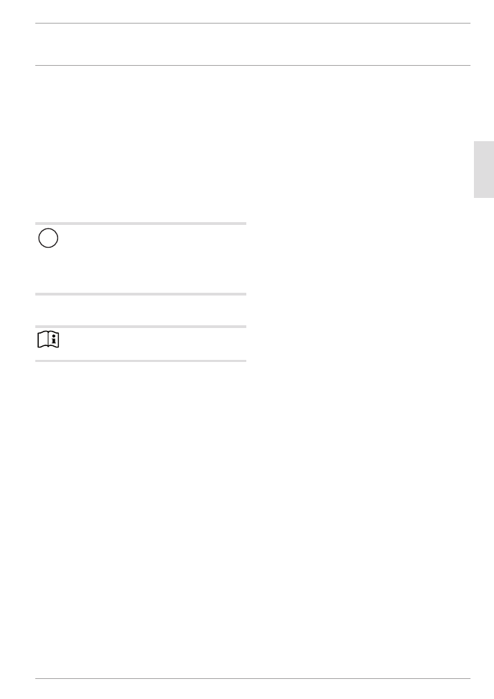
If you cannot remedy the fault, notify your qualified contractor.
To facilitate and speed up your request, provide the number from
the type plate (000000-0000-000000).
D
00000
51
86
6
DHB ... STi
INSTALLATIoN
Safety
www.stiebel-eltron.com
DHB STi |
21
EN
GL
ISH
INSTALLATIoN
7. Safety
Only a qualified contractor should carry out installation, commis-
sioning, maintenance and repair of the appliance.
7.1 General safety instructions
We guarantee trouble-free functioning and operational reliabil-
ity only if original accessories and spare parts intended for the
appliance are used.
!
Material losses
Observe the maximum permissible inlet temperature (see
chapter "Installation / Specification / Data table"). Higher
temperatures may damage the appliance. You can limit
the inlet temperature by means of a central thermostatic
valve (see chapter "Installation / Appliance description /
Accessories").
7.2 Instructions, standards and regulations
Note
Observe all applicable national and regional regulations
and instructions.
- The IP 25 (hoseproof) rating can only be ensured with a cor-
rectly fitted cable grommet.
- The specific electrical resistance of the water must not fall
below that stated on the type plate. In a linked water net-
work, factor in the lowest electrical resistance of the water
(see chapter "Installation / Specification / Data table"). Your
water supply utility will advise you of the specific electrical
water resistance or conductivity.
8. Appliance description
8.1 Standard delivery
The following are delivered with the appliance:
- Wall mounting bracket
- Installation plate
- 2 twin connectors
- Cold water 3-way ball shut-off valve
- DHW tee
- Flat gaskets
- Strainer
- Flow limiter
- Plastic profile washer
- Plastic connection pieces / installation aid
- Cover guides
8.2 Accessories
Taps
- MEKD mono lever kitchen pressure tap
- MEBD mono lever bath pressure tap
Plug G ½ A
If you use pressure taps on finished walls other than those rec-
ommended in the accessories, please use plugs.
Installation set for finished walls
- Brazing fitting - copper pipe for brazed connection Ø 12 mm
- Compression fitting - copper pipe
- Compression fitting - plastic pipe (suitable for Viega: San-
fix-Plus or Sanfix-Fosta)
Universal mounting frame
- Mounting frame with electrical connections
Pipe assembly for undersink appliances
You will need the undersink installation set if you make the water
connections (G ⅜ A) at the top of the appliance.
Pipe assembly for offset installation
You will need this pipe assembly set if you intend to offset the
appliance by 90 mm downwards from the water connection.
Pipe assembly for replacing a gas water heater
You will need this pipe assembly set if the existing installation
has gas water heater connections (cold water connection on the
left-hand side, DHW connection on the right-hand side).
Pipe assembly DHB water plug-in couplings
Use the water plug-in couplings if the existing installation has
water plug-in connections from an instantaneous water heater.
Load shedding relay (LR 1-A)
The load shedding relay for installation in the distribution board
provides priority control for the instantaneous water heater when
other appliances, such as electric storage heaters, are being op-
erated simultaneously.
INSTALLATIoN
Preparations
22
| DHB STi
www.stiebel-eltron.com
9. Preparations
9.1 Installation site
!
Material losses
Install the appliance in a room free from the risk of frost.
f
f
Always install the appliance vertically and near the draw-off
point.
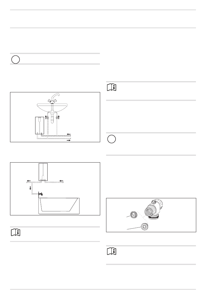
The appliance is suitable for undersink and oversink installations.
Undersink installation
1
2
26
�0
2�
02
�0
84
4
1 Cold water Inlet
2 DHW outlet
Oversink installation
2
1
26
�0
2�
02
�0
84
5
1 Cold water Inlet
2 DHW outlet
Note
f
f
Mount the appliance on the wall. The wall must have
a sufficient load-bearing capacity.
9.2 Water installation
- A safety valve is not required.
- Never operate with preheated water.
f
f
Flush the water line thoroughly.
Taps
Use suitable pressure taps/valves (see chapter "Installation /
Appliance description / Accessories"). Open vented taps are not
permitted.
Note
Never use the 3-way ball shut-off valve in the cold water
inlet to reduce the flow rate. The 3-way ball shut-off valve
is intended to shut off the appliance.
Permissible water line materials
- Cold water inlet line:
Pipes made from galvanised steel, stainless steel, copper or
plastic
- DHW outlet line:
Pipes made from stainless steel, copper or plastic
!
Material losses
If plastic pipework is used, take into account the max-
imum inlet temperature and the maximum permissible
pressure (see chapter "Installation / Specification / Data
table").
Flow rate
f
f
Ensure that the flow rate for switching on the appliance is
achieved (see chapter "Installation / Specification / Data
table", On).
f
f
Increase the water line pressure if the required flow rate is
not achieved when the draw-off valve is fully open. If the
flow rate is not reached despite increasing the pressure, re-
move the flow limiter and install the plastic profile washer.
2
1
26
�0
2�
02
�0
82
0
1 Flow limiter
2 Plastic profile washer
Note
For the thermostatic valve to function correctly, the flow
limiter must not be replaced with the plastic profile wash-
er.
INSTALLATIoN
Installation
www.stiebel-eltron.com
DHB STi |
23
EN
GL
ISH
10. Installation
Standard installation
- Electrical connection from below on unfinished walls
- Water connection on unfinished walls
For further installation options, see chapter "Installation /
Installation options":
- Electrical connection from above on unfinished walls
- Electrical connection on finished walls
- Large conductor cross-section for electrical connection from
below
- Connecting a load shedding relay
- Water installation on finished walls
- Water installation on finished walls with brazing / compres-
sion fitting
- Water installation on finished walls; fitting the appliance
cover
- Installation of lower back panel with threaded fittings on fin-
ished walls
- Wall mounting bracket when replacing an appliance
- Installation with offset tiles
- Pivoting appliance cover
10.1 Standard installation
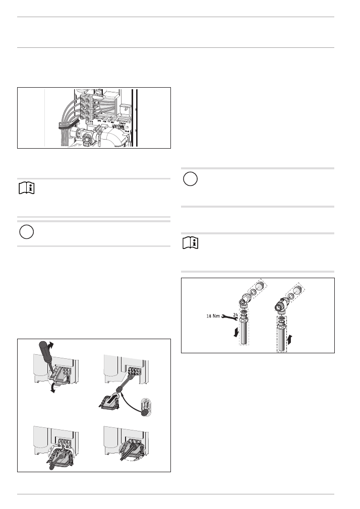
Opening the appliance
26
�0
2�
02
�0
86
4
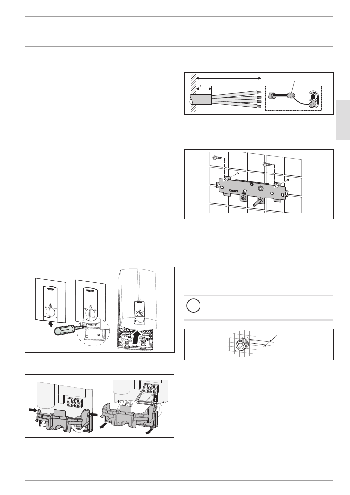
f
f
Open the appliance by pulling the flap downwards, undo the
screw and lift up the appliance cover.
26
�02
�02
�1
10
1
f
f
Remove the back panel by pressing the two locking hooks
and pulling the lower section of the back panel forwards.
Preparing the power cable
160
30
1
26
�0
2�
02
�0
82
4�
1 Installation aid
f
f
Prepare the power cable.
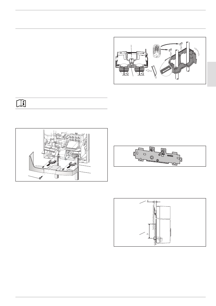
Fitting the wall mounting bracket
26
�0
2�
02
�0
81
0�
f
f
Mark out the holes for drilling using the installation plate.
If the appliance is to be installed with water connections on
finished walls, also mark out a fixing hole in the lower part
of the template.
f
f
Drill the holes and secure the wall mounting bracket with
2 screws and 2 rawl plugs (screws and rawl plugs are not
part of the standard delivery).
f
f
Fit the wall mounting bracket.
Making the water connection
!
Material losses
Carry out all water connection and installation work in
accordance with regulations.
12
D
00000
53
31
9
f
f
Seal and insert the twin connectors.
INSTALLATIoN
Installation
24
| DHB STi
www.stiebel-eltron.com
D
00000
50
94
7
1
4
5
2
3
2
1 DHW with tee
2 Gasket
3 Cold water with 3-way ball shut-off valve
4 Strainer
5 Flow limiter or plastic profile washer (see chapter "Installa-
tion / Water installation / Flow rate")
f
f
Secure the tee and 3-way ball shut-off valve, each with a flat
gasket, to the twin connectors.
!
Material losses
Never use the 3-way ball shut-off valve in the cold water
inlet to reduce the flow rate.
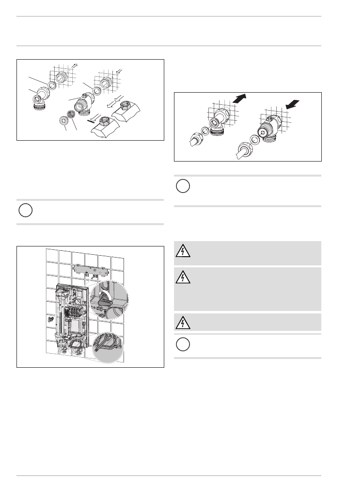
Installing the appliance
26
�0
2�
02
�0
81
1
f
f
For easy installation, push the cable grommet of the upper
electrical connection into the back panel from behind.
f
f
Remove the transport plugs from the water connections.
f
f
Remove the fixing toggle from the upper part of the back
panel.
f
f
Route the power cable through the cable grommet from
behind until the power cable rests against the cable sheath.
Align the power cable.
Enlarge the hole in the cable grommet if the cross-section of
the power cable is > 6 mm².
f
f
Push the appliance over the threaded stud of the wall mount-
ing bracket, so that it breaks through the soft seal. If neces-
sary, use a screwdriver.
f
f
Push the fixing toggle on to the threaded stud of the wall
mounting bracket.
f
f
Push the back panel firmly against the wall. Lock the fixing
toggle by turning it 90° clockwise.
26
�0
2�
02
�0
85
8
f
f
Fit the pipes with flat gaskets onto the twin connectors.
!
Material losses
The strainer must be fitted for the appliance to function.
f
f
When replacing an appliance, check whether the
strainer is installed.
f
f
Open the 3-way ball shut-off valve or the shut-off valve in the
cold water supply line.
Making the electrical connection
WARNING Electrocution
Carry out all electrical connection and installation work
in accordance with relevant regulations.
WARNING Electrocution
The connection to the power supply must be in the form
of a permanent connection in conjunction with the re-
movable cable grommet. Ensure the appliance can be
separated from the power supply by an isolator that dis-
connects all poles with at least 3 mm contact separation.
WARNING Electrocution
Ensure that the appliance is earthed.
!
Material losses
Observe the type plate. The specified voltage must match
the mains voltage.
f
f
Connect the power cable to the mains terminal (see chapter
"Installation / Specification / Wiring diagrams").
INSTALLATIoN
Commissioning
www.stiebel-eltron.com
DHB STi |
25
EN
GL
ISH
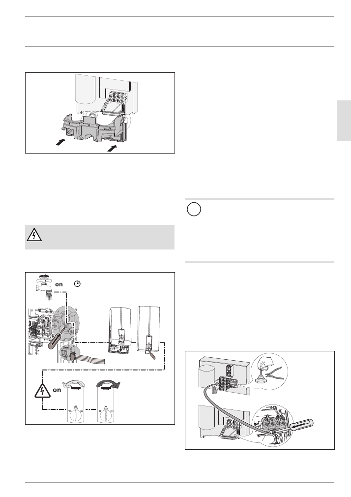
Fitting the lower back panel
26
�02
�02
�1
102
�
f
f
Fit the lower back panel into the back panel. Click the lower
back panel into place.
f
f
Align the mounted appliance by loosening the fixing toggle,
aligning the power supply and back panel, and then re-tight-
ening the fixing toggle. If the back panel of the appliance is
not flush, you can secure the appliance at the bottom with an
additional screw.
11. Commissioning
WARNING Electrocution
Commissioning may only be carried out by a qualified
contractor in accordance with safety regulations.
11.1 Initial start-up
≥ 60 s
D
00000
51
87
7
f
f
Open and close all connected draw-off valves several times,
until all air has been purged from the pipework and the
appliance.
f
f
Carry out a tightness check.
f
f
Activate the safety pressure limiter under flow pressure by
firmly pressing in the reset button (the appliance is delivered
with the safety pressure limiter disabled).
f
f
Plug the set value transducer cable plug into the PCB.
f
f
Fit the appliance cover. Check that the appliance cover is
seated correctly.
f
f
Secure the appliance cover with the screw.
f
f
Switch the mains power ON.
f
f
Calibrate the temperature. Turn the temperature selector
fully clockwise then fully anti-clockwise.
f
f
Remove the protective foil from the control fascia.
f
f
Check the function of the appliance.
Appliance handover
f
f
Explain the appliance function to users and familiarise them
with its operation.
f
f
Make the user aware of potential dangers, especially the risk
of scalding.
f
f
Hand over these instructions.
11.2 Recommissioning
!
Material losses
To ensure that the bare wire heating system is not dam-
aged following an interruption to the water supply, the
appliance must be restarted in the following sequence.
f
f
Disconnect the appliance from the power supply by
removing the fuses/tripping the MCBs.
f
f
Open the tap for one minute until the appliance and
its upstream cold water inlet line are free of air.
f
f
Switch the mains power back ON again.
12. Shutdown
f
f
Isolate all poles of the appliance from the power supply.
f
f
Drain the appliance (see chapter "Installation / Maintenance /
Draining the appliance").
13. Alternative installation options
13.1 Electrical connection from above on unfinished
walls
26
�02
�02
�1
12
3�
f
f
Cut open the cable grommet for the power cable.
f
f
Push down the locking hook to secure the mains terminal.
Pull out the mains terminal.
INSTALLATIoN
Alternative installation options
26
| DHB STi
www.stiebel-eltron.com
f
f
Reposition the mains terminal from the bottom to the top.
Secure the mains terminal by pushing it under the locking
hook.
26
�02
�02
�1
30
6�
f
f
Lay the control wires below the wire guide.
13.2 Electrical connection on finished walls
Note
This type of connection changes the protection rating of
the appliance.
f
f
Change the type plate. Cross out "IP 25" and mark
the box "IP 24". Please use a ballpoint pen to do this.
!
Material losses
If you break out the wrong knock-out by mistake, use a
new back panel.
f
f
Cleanly cut or break out the required cable entries in the
back panel (for positions, see chapter "Installation / Specifi-
cation / Dimensions and connections"). Deburr sharp edges
with a file if necessary.
f
f
Route the power cable through the cable grommet and con-
nect the power cable to the mains terminal.
13.3 Large conductor cross-section for electrical
connection from below
If you use cables with a large cross-section, you can fit the cable
grommet after the appliance has been installed.
1.
3.
4.
2.
26
�02
�02
�1
12
4�
f
f
Before installing the appliance, use a screwdriver to push out
the cable grommet.
f
f
Slide the cable grommet over the power cable. Use the
installation aid supplied in the standard delivery. If the
cross-section is > 6 mm², enlarge the hole in the cable
grommet.
f
f
Push the cable grommet into the back panel. Engage the
cable grommet in position.
13.4 Connecting a load shedding relay
When operating additional electric appliances, such as electric
storage heaters, install a load shedding relay in the distribution
board. The relay responds when the instantaneous water heater
starts.
!
Material losses
Connect the phase that switches the load shedding relay
to the indicated terminal of the mains terminal in the ap-
pliance (see chapter "Installation / Specification / Wiring
diagrams").
13.5 Water installation on finished walls
Note
This type of connection changes the protection rating of
the appliance.
f
f
Change the type plate. Cross out "IP 25" and mark
the box "IP 24". Please use a ballpoint pen to do this.
D
00000
33
10
4
f
f
Fit water plugs with gaskets to seal the connection on unfin-
ished walls. All taps listed under "Accessories" are supplied
with plugs and gaskets as part of their standard delivery. For
pressure taps other than those we recommend, plugs and
gaskets can be ordered as "Accessories".
f
f
Fit a suitable pressure tap.
f
f
Push the lower part of the back panel under the connecting
pipes of the tap and push it into the back panel.
f
f
Fit the connection pipes together with the tee and 3-way ball
shut-off valve.
INSTALLATIoN
Alternative installation options
www.stiebel-eltron.com
DHB STi |
27
EN
GL
ISH
13.6 Water installation on finished walls with
brazing / compression fitting
You can connect copper or plastic pipes with "solder fittings" or
"compression fittings" (accessories).
With "solder fittings" with threaded connection for 12 mm copper
pipes, proceed as follows:
f
f
Push the union nuts over the connection pipes.
f
f
Braze the inserts to the copper pipes.
f
f
Push the lower part of the back panel under the connecting
pipes of the tap and push it into the back panel.
f
f
Fit the connection pipes together with the tee and 3-way ball
shut-off valve.
Note
Observe the tap manufacturer's instructions.
13.7 Water installation on finished walls; fitting the
appliance cover
1
2
3
26
�0
2�
02
�0
52
5
1 Cover guides
2 Pipe aperture
3 Screw
f
f
Cleanly break out the knock-outs in the appliance cover. If
necessary, use a file.
f
f
Click the cover guides into place in the knock-outs.
f
f
Secure the back panel at the bottom with a screw.
f
f
If you use flexible water connection pipes, please pre-
vent pipe bends from twisting (bayonet connections in the
appliance).
13.8 Installation of lower back panel with threaded
fittings on finished walls
If using threaded connections for finished walls, the lower part of
the back panel can also be installed after fitting the taps/valves.
To do this, carry out the following steps:
f
f
With a saw, cut open the lower section of the back panel.
f
f
Fit the lower section of the back panel by bending it out at
the sides and guiding it over the pipes.
f
f
Insert the connection pieces into the lower section of the
back panel from behind.
f
f
Click the lower section of the back panel into place.
f
f
Secure the lower section of the back panel with a screw.
2
1
3
26
�0
2�
02
�1
08
0
1 Back panel bottom section
2 Connection pieces delivered in the pack
3 Screw
13.9 Wall mounting bracket when replacing an
appliance
An existing STIEBEL ELTRON wall mounting bracket may be used
when replacing appliances (except instantaneous water heater
DHF).
f
f
Break through the back panel of the appliance for the thread-
ed stud on the installed wall mounting bracket.
Replacing instantaneous water heater DHF
26
�0
2�
02
�0
81
5�
f
f
Reposition the threaded stud on the wall mounting bracket
(the stud has a self-tapping thread).
f
f
Rotate the wall mounting bracket 180° and mount it on the
wall (the DHF logo is then turned towards the reader).
13.10 Installation with offset tiles
11
0
20
26
�02
�02
�1
06
6�
2
1
1 Minimum contact area of the appliance
2 Maximum tile offset
f
f
Adjust the wall clearance. Lock the back panel in place using
the fixing toggle (turn through 90° clockwise).

INSTALLATIoN
Alternative installation options
28
| DHB STi
www.stiebel-eltron.com
13.11 Pivoting appliance cover
The appliance cover can be rotated for undersink installation.
26
�0
2�
02
�0
86
5
f
f
Remove the programming unit from the appliance cover by
undoing the screws.
f
f
Turn the appliance cover (not the appliance) and refit the
programming unit.
f
f
Plug the set value transducer cable into the PCB (see chapter
"Installation / Commissioning / Initial start-up").
f
f
Hook the appliance cover in at the top. Swivel the appliance
cover down onto the back panel and press it until it engages
audibly.
f
f
Secure the appliance cover.
INSTALLATIoN
Troubleshooting
www.stiebel-eltron.com
DHB STi |
29
EN
GL
ISH
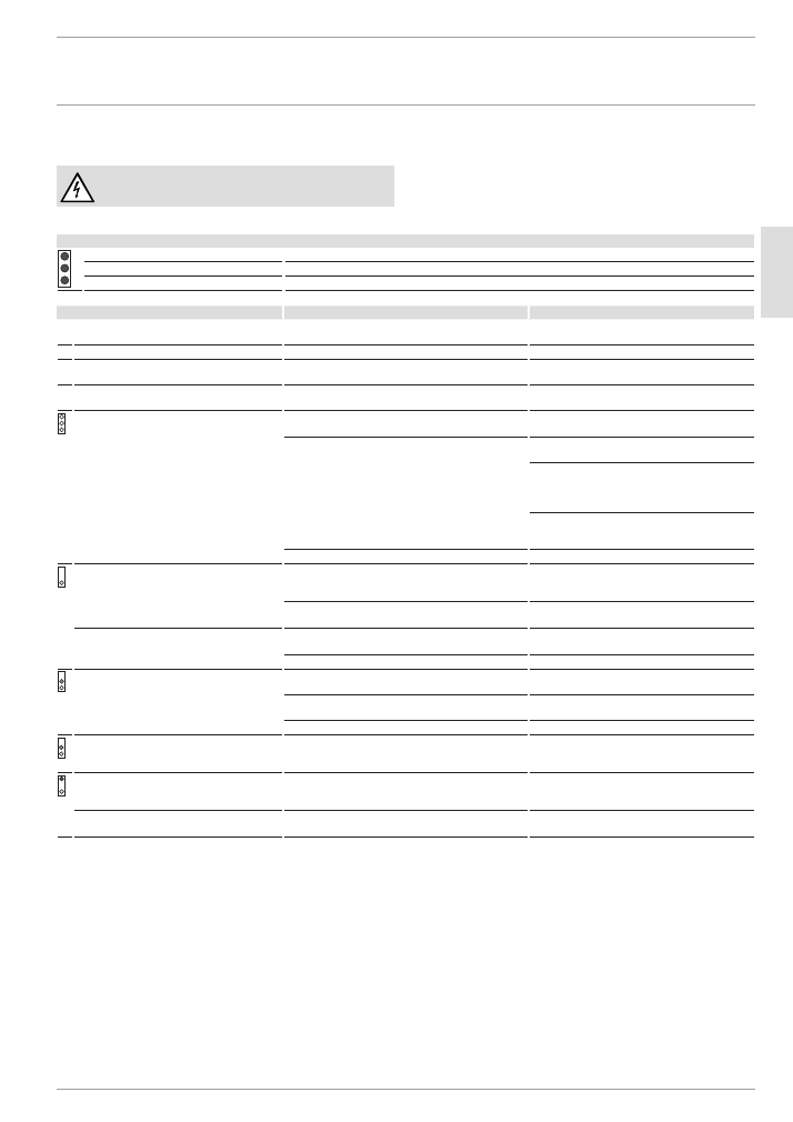
14. Troubleshooting
WARNING Electrocution
To test the appliance, it must be supplied with power.
Possible indications of diagnostic traffic light (LeD)
Red
Illuminates in the event of a fault
Yellow
Illuminates during heating mode
Green
Flashing: Appliance is supplied with mains power
fault / diagnostic traffic light LeD
Cause
remedy
The appliance does not start.
The shower head / aerators are scaled up.
Descale or if necessary replace the shower head /
aerators.
The flow rate is too low.
The strainer in the appliance is dirty.
Clean the strainer.
The set temperature is not achieved.
One phase down.
Check the fuse/MCB in your fuse box/distribution
panel.
The heater switches off.
The air detector senses air in the water. Heating output
cuts out temporarily.
The appliance restarts after one minute.
No hot water and no traffic light display.
The MCB/fuse has responded/blown.
Check the fuse/MCB in your fuse box/distribution
panel.
Safety pressure limiter AP 3 has tripped.
Remove the cause of the fault (e.g. faulty pressure
flush).
Protect the heating system against overheating by
opening a draw-off valve downstream from the ap-
pliance for one minute. This depressurises and cools
down the heating system.
Activate the safety pressure limiter at flow pressure
by pressing the reset button, also see chapter "In-
stallation / Commissioning / Initial start-up".
The PCB is faulty.
Check the PCB and replace if necessary.
Traffic light display: Green flashing
No hot water at flow rate
> 3 l/min.
Flow sensor DFE is not plugged in.
Re-insert the flow sensor plug.
Flow sensor DFE is faulty.
Check the flow sensor and replace if necessary.
The set temperature is not achieved.
The set value transducer or connecting cable is faulty, or
the connecting cable is not attached.
Attach the connecting cable; replace the set value
transducer if required.
Temperature limiting is enabled.
Disable temperature limiting.
Traffic light display: Yellow constantly on; green
flashing
No hot water at flow rate
> 3 l/min.
The high limit safety cut-out has responded or its lead
is broken.
Check the high limit safety cut-out and replace if
necessary.
The heating system is faulty.
Check the resistance of the heater and replace if
necessary.
The PCB is faulty.
Check the PCB and replace if necessary.
Traffic light display: Yellow constantly on; green
flashing
Set temperature not reached.
Appliance is operating at its output limit.
Reduce the flow rate. Install the flow limiter.
Traffic light display: Red constantly on; green
flashing
No hot water
The cold water sensor is faulty.
Check the PCB and replace if necessary.
Required temperature > 35 °C not reached
The cold water inlet temperature exceeds 45 °C.
Reduce the cold water inlet temperature to the ap-
pliance.
INSTALLATIoN
Maintenance
30
| DHB STi
www.stiebel-eltron.com
15. Maintenance
WARNING Electrocution
Before any work on the appliance, disconnect it omnip-
olar from the power supply.
Draining the appliance
The appliance can be drained for maintenance work.
WARNING Scalding
Hot water may escape when you drain the appliance.
f
f
Close the 3-way shut-off valve or the shut-off valve in the
cold water supply line.
f
f
Open all draw-off valves.
f
f
Undo the water connections on the appliance.
f
f
If dismantled, store the appliance in a room free from the
risk of frost, as water residues remaining inside the appli-
ance can freeze and cause damage.
Cleaning the strainer
If contaminated, clean the strainer in the threaded cold water
fitting. Close the 3-way shut-off valve or the shut-off valve in the
cold water supply line before removing, cleaning and refitting
the strainer.
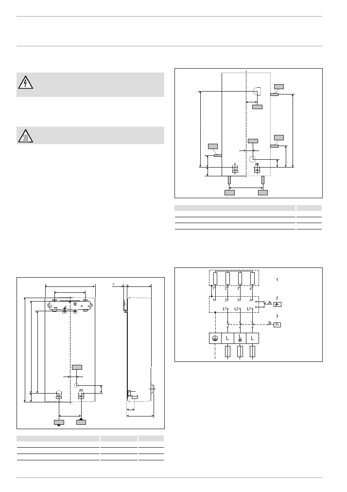
16. Specification
16.1 Dimensions and connections
b02
c01
c06
47
0
100
41
4
40
110
20
225
140
35
35
121
36
8
30
D
00000
51
85
7
DHB STi
b02 Entry cables I
c01 Cold water Inlet
Male thread
G 1/2 A
c06 DHW outlet
Male thread
G 1/2 A
Alternative connection options
165
50
44
30
35
72
325
338
47
b03
b02
b04
b04
b04
b04
b04
D
00000
19
21
2
DHB STi
b02 Entry cables I
b03 Entry cables II
b04 Entry cables III
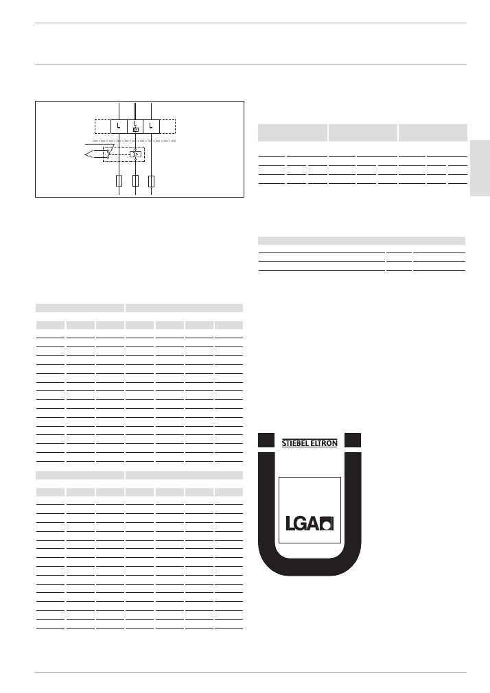
16.2 Wiring diagram
3/PE ~ 380-415 V
85
�0
2�
02
�0
00
5
1 Heater
2 High limit safety cut-out
3 Safety pressure limiter
INSTALLATIoN
Specification
www.stiebel-eltron.com
DHB STi |
31
EN
GL
ISH
Priority control with LR 1-A
85
�0
2�
02
�0
00
3�
2
1
1 Control cable to the contactor of the second appliance (elec-
tric storage heater for example).
2 Control contact opens when switching the instantaneous
water heater on.
16.3 DHW output
The DHW output is subject to the mains voltage, the appliance's
connected load and the cold water inlet temperature. The rated
voltage and rated output can be found on the type plate (see
chapter "Operation / Troubleshooting").
Connected load in kw
38 °C DHw output in l/min.
Rated voltage
Cold water inlet temperature
380 V
400 V
415 V
5 °C
10 °C
15 °C
20 °C
16.2
7.0
8.3
10.1
12.9
16.3
7.1
8.3
10.1
12.9
18.0
7.8
9.2
11.2
14.3
19.0
8.2
9.7
11.8
15.1
19.4
8.4
9.9
12.0
15.4
21.0
9.1
10.7
13.0
16.7
21.7
9.4
11.1
13.5
17.2
22.6
9.8
11.5
14.0
17.9
23.5
10.2
12.0
14.6
18.7
24.0
10.4
12.2
14.9
19.0
24.4
10.6
12.4
15.2
19.4
25.8
11.2
13.2
16.0
20.5
26.0
11.3
13.3
16.1
20.6
27.0
11.7
13.8
16.8
21.4
28.0
12.1
14.3
17.4
22.2
Connected load in kw
50 °C DHw output in l/min.
Rated voltage
Cold water inlet temperature
380 V
400 V
415 V
5 °C
10 °C
15 °C
20 °C
16.2
5.1
5.8
6.6
7.7
16.3
5.2
5.8
6.7
7.8
18.0
5.7
6.4
7.3
8.6
19.0
6.0
6.8
7.8
9.0
19.4
6.2
6.9
7.9
9.2
21.0
6.7
7.5
8.6
10.0
21.7
6.9
7.8
8.9
10.3
22.6
7.2
8.1
9.2
10.8
23.5
7.5
8.4
9.6
11.2
24.0
7.6
8.6
9.8
11.4
24.4
7.7
8.7
10.0
11.6
25.8
8.2
9.2
10.5
12.3
26.0
8.3
9.3
10.6
12.4
27.0
8.6
9.6
11.0
12.9
28.0
8.9
10.0
11.4
13.3
16.4 Application areas / conversion table
Specific electrical resistance and specific electrical conductivity
(see chapter "Installation / Data table").
Standard specifica-
tion at 15 °C
20 °C
25 °C
Resist-
ance ρ
≥
Conductivity
σ
≤
Resist-
ance ρ
≥
Conductivity
σ
≤
Resist-
ance ρ
≥
Conductivity
σ
≤
Ωcm
mS/m μS/cm Ωcm
mS/m μS/cm Ωcm
mS/m μS/cm
1100
91
909
970
103
1031
895
112
1117
1200
83
833
1070
93
935
985
102
1015
16.5 Pressure drop
Taps
Tap pressure drop at a flow rate of 10 l/min
Mono lever mixer tap, approx.
MPa
0.04 - 0.08
Thermostatic valve, approx.
MPa
0.03 - 0.05
Shower head, approx.
MPa
0.03 - 0.15
Sizing the pipework
When calculating the size of the pipework, an appliance pressure
drop of 0.1 MPa is recommended.
16.6 Fault conditions
In case of faults, loads up to a maximum of 95 °C at a pressure of
1.2 MPa can occur temporarily in the installation.
16.7 Country-specific approvals and certifications:
Germany
A general test certificate as verification of suitability regarding
noise emissions has been issued for this appliance, based on the
State Building Regulations [Germany].
DIN 4109
PA-IX 6816/I
INSTALLATIoN
Specification
32
| DHB STi
www.stiebel-eltron.com
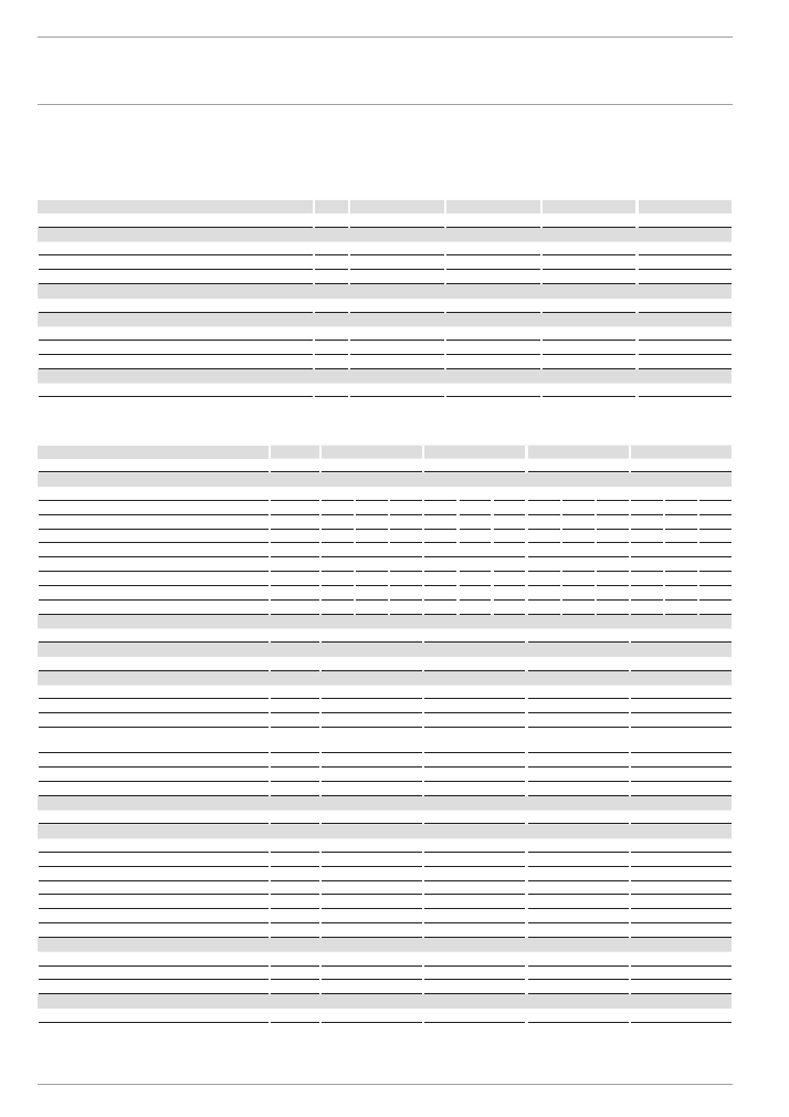
16.8 Details on energy consumption
Product data complies with EU regulations relating to the Directive
on the ecodesign of energy-related products (ErP).
DHB 18 STi
DHB 21 STi
DHB 24 STi
DHB 27 STi
227612
227613
227614
227615
Versions
Manufacturer
STIEBEL ELTRON
STIEBEL ELTRON
STIEBEL ELTRON
STIEBEL ELTRON
Default temperature setting
°C
55
55
55
55
Special information on measuring efficiency
None
None
None
None
Output data
Load profile
S
S
S
S
Energy data
Energy efficiency category
A
A
A
A
Annual power consumption
kWh
480
477
475
475
Energy efficiency
%
39
39
39
39
Sound data
Sound power level
dB(A)
15
15
15
15
16.9 Data table
DHB 18 STi
DHB 21 STi
DHB 24 STi
DHB 27 STi
227612
227613
227614
227615
Electrical details
Rated voltage
V
380
400
415
380
400
415
380
400
415
380
400
415
Rated output
kW
16.2
18
19.4
19
21
22.6
21.7
24
25.8
23.5
26
28
Rated current
A
24.7
26
27
29.5
31
32.2
33.3
35
36.3
35.6
37.7
38.9
Fuse
A
25
25
32
32
32
32
35
35
40
35
40
40
Phases
3/PE
3/PE
3/PE
3/PE
Frequency
Hz 50/60 50/60
50/- 50/60 50/60
50/- 50/60 50/60
50/-
50/-
50/-
50/-
Max. mains impedance at 50Hz
Ω
0.379
0.360
0.347
0.325 0.308
0.297
0.284
0.270
0.260
0.254
0.241
Specific resistance ρ
15
≥ (at
ϑ
cold ≤35 °C)
Ω cm ≥1100 ≥1100 ≥1200 ≥1100 ≥1100 ≥1200 ≥1100 ≥1100 ≥1200 ≥1100 ≥1100 ≥1200
Specific conductivity
σ
15
≤ (at
ϑ
cold ≤35 °C)
μS/cm
≤910
≤910
≤830
≤910
≤910
≤830
≤910
≤910
≤830
≤910
≤910
≤830
Connections
Water connection
G 1/2 A
G 1/2 A
G 1/2 A
G 1/2 A
Application limits
Max. permissible pressure
MPa
1
1
1
1
Values
Max. permissible inlet temperature
°C
35
35
35
35
ON
l/min
> 3.0
> 3.0
> 3.0
> 3.0
Flow rate for pressure drop
l/min
5.2
6.0
6.9
7.7
Pressure drop at flow rate
MPa
0.08 (0.06 without
DMB)
0.1 (0.08 without DMB) 0.13 (0.1 without DMB)
0.16 (0.12 without
DMB)
Flow rate limit at
l/min
7.5
7.5
8.5
8.5
DHW delivery
l/min
9.2
10.7
12.3
13.8
Δ
ϑ
at DHW delivery
K
28
28
28
28
Hydraulic data
Rated capacity
l
0.4
0.4
0.4
0.4
Versions
Temperature adjustment
°C
Approx. 35, 45, 55
Approx. 35, 45, 55
Approx. 35, 45, 55
Approx. 35, 45, 55
Protection class
1
1
1
1
Insulation block
Plastic
Plastic
Plastic
Plastic
Heating system heat generator
Bare wire
Bare wire
Bare wire
Bare wire
Cap and back panel
Plastic
Plastic
Plastic
Plastic
Colour
white
white
white
white
IP rating
IP25
IP25
IP25
IP25
Dimensions
Height
mm
470
470
470
470
Width
mm
225
225
225
225
Depth
mm
110
110
110
110
Weights
Weight
kg
3.6
3.6
3.6
3.6

www.stiebel-eltron.com
DHB STi |
33
EN
GL
ISH
GUARANTEE | ENVIRONMENT AND RECYCLING
guArANTee
eNVIroNMeNT AND reCYCLINg
Guarantee
The guarantee conditions of our German companies do not
apply to appliances acquired outside of Germany. In countries
where our subsidiaries sell our products a guarantee can only
be issued by those subsidiaries. Such guarantee is only grant-
ed if the subsidiary has issued its own terms of guarantee. No
other guarantee will be granted.
We shall not provide any guarantee for appliances acquired in
countries where we have no subsidiary to sell our products.
This will not affect warranties issued by any importers.
Environment and recycling
We would ask you to help protect the environment. After use,
dispose of the various materials in accordance with national
regulations.

Deutschland
STIEBEL ELTRON GmbH & Co. KG
Dr.-Stiebel-Straße 33 | 37603 Holzminden
Tel. 05531 702-0 | Fax 05531 702-480
info@stiebel-eltron.de
www.stiebel-eltron.de
Verkauf
Tel. 05531 702-110 | Fax 05531 702-95108 | info-center@stiebel-eltron.de
Kundendienst
Tel. 05531 702-111 | Fax 05531 702-95890 | kundendienst@stiebel-eltron.de
Ersatzteilverkauf
Tel. 05531 702-120 | Fax 05531 702-95335 | ersatzteile@stiebel-eltron.de
Irrtum und technische Änderungen vorbehalten! | Subject to errors and technical changes! | Sous réserve
d‘erreurs et de modifications techniques! | Onder voorbehoud van vergissingen en technische wijzigingen! |
Salvo error o modificación técnica! | Excepto erro ou alteração técnica | Zastrzeżone zmiany techniczne i
ewentualne błędy | Omyly a technické změny jsou vyhrazeny! | A muszaki változtatások és tévedések jogát
fenntartjuk! |
Отсутствие ошибок не гарантируется. Возможны технические изменения.
| Chyby a
technické zmeny sú vyhradené!
Stand 9046
Australia
STIEBEL ELTRON Australia Pty. Ltd.
6 Prohasky Street | Port Melbourne VIC 3207
Tel. 03 9645-1833 | Fax 03 9645-4366
info@stiebel.com.au
www.stiebel.com.au
Austria
STIEBEL ELTRON Ges.m.b.H.
Eferdinger Str. 73 | 4600 Wels
Tel. 07242 47367-0 | Fax 07242 47367-42
info@stiebel-eltron.at
www.stiebel-eltron.at
Belgium
STIEBEL ELTRON bvba/sprl
't Hofveld 6 - D1 | 1702 Groot-Bijgaarden
Tel. 02 42322-22 | Fax 02 42322-12
info@stiebel-eltron.be
www.stiebel-eltron.be
China
STIEBEL ELTRON (Guangzhou) Electric
Appliance Co., Ltd.
Rm 102, F1, Yingbin-Yihao Mansion, No. 1
Yingbin Road
Panyu District | 511431 Guangzhou
Tel. 020 39162209 | Fax 020 39162203
info@stiebeleltron.cn
www.stiebeleltron.cn
Czech Republic
STIEBEL ELTRON spol. s r.o.
K Hájům 946 | 155 00 Praha 5 - Stodůlky
Tel. 251116-111 | Fax 235512-122
info@stiebel-eltron.cz
www.stiebel-eltron.cz
Finland
STIEBEL ELTRON OY
Kapinakuja 1 | 04600 Mäntsälä
Tel. 020 720-9988
info@stiebel-eltron.fi
www.stiebel-eltron.fi
France
STIEBEL ELTRON SAS
7-9, rue des Selliers
B.P 85107 | 57073 Metz-Cédex 3
Tel. 0387 7438-88 | Fax 0387 7468-26
info@stiebel-eltron.fr
www.stiebel-eltron.fr
Hungary
STIEBEL ELTRON Kft.
Gyár u. 2 | 2040 Budaörs
Tel. 01 250-6055 | Fax 01 368-8097
info@stiebel-eltron.hu
www.stiebel-eltron.hu
Japan
NIHON STIEBEL Co. Ltd.
Kowa Kawasaki Nishiguchi Building 8F
66-2 Horikawa-Cho
Saiwai-Ku | 212-0013 Kawasaki
Tel. 044 540-3200 | Fax 044 540-3210
info@nihonstiebel.co.jp
www.nihonstiebel.co.jp
Netherlands
STIEBEL ELTRON Nederland B.V.
Daviottenweg 36 | 5222 BH 's-Hertogenbosch
Tel. 073 623-0000 | Fax 073 623-1141
info@stiebel-eltron.nl
www.stiebel-eltron.nl
Poland
STIEBEL ELTRON Polska Sp. z O.O.
ul. Działkowa 2 | 02-234 Warszawa
Tel. 022 60920-30 | Fax 022 60920-29
biuro@stiebel-eltron.pl
www.stiebel-eltron.pl
Russia
STIEBEL ELTRON LLC RUSSIA
Urzhumskaya street 4,
building 2 | 129343 Moscow
Tel. 0495 7753889 | Fax 0495 7753887
info@stiebel-eltron.ru
www.stiebel-eltron.ru
Slovakia
TATRAMAT - ohrievače vody s.r.o.
Hlavná 1 | 058 01 Poprad
Tel. 052 7127-125 | Fax 052 7127-148
info@stiebel-eltron.sk
www.stiebel-eltron.sk
Switzerland
STIEBEL ELTRON AG
Industrie West
Gass 8 | 5242 Lupfig
Tel. 056 4640-500 | Fax 056 4640-501
info@stiebel-eltron.ch
www.stiebel-eltron.ch
Thailand
STIEBEL ELTRON Asia Ltd.
469 Moo 2 Tambol Klong-Jik
Amphur Bangpa-In | 13160 Ayutthaya
Tel. 035 220088 | Fax 035 221188
info@stiebeleltronasia.com
www.stiebeleltronasia.com
United Kingdom and Ireland
STIEBEL ELTRON UK Ltd.
Unit 12 Stadium Court
Stadium Road | CH62 3RP Bromborough
Tel. 0151 346-2300 | Fax 0151 334-2913
info@stiebel-eltron.co.uk
www.stiebel-eltron.co.uk
United States of America
STIEBEL ELTRON, Inc.
17 West Street | 01088 West Hatfield MA
Tel. 0413 247-3380 | Fax 0413 247-3369
info@stiebel-eltron-usa.com
www.stiebel-eltron-usa.com
A 283362-38950-9074
B
283036-38680-9047 M
4<AMHCMN=iddgcj>