Full Text Searchable PDF User Manual
SERVICE INSTRUCTION
E F F I C I E N C Y I N D E N T I S T R Y
®
ELECTROLS UPGRADE AND REPLACEMENT
How to properly upgrade the gray box Electrols to S1
Electrols, and how to replace the S1 Electrols PC Board
BULLDOG MODELS
Procedures
Important Features
1 Phase Gray Box Electrols Upgrade
3 Phase Gray Box Electrols Upgrade
S1 Electrols PC Board Replacement
3 Phase Motor Startup
Page
6
7
8
14
15
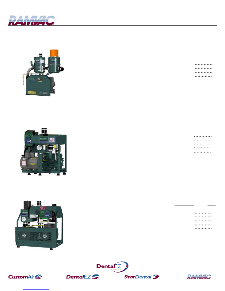
• 550
(855.xxxx.xxx)
• QT
(809.xxxx.xxx)
• QT E
(809E.xxxx.xxx)
BISON MODELS
Procedures
Important Features
1 Phase Gray Box Electrols Upgrade
3 Phase Gray Box Electrols Upgrade
S1 Electrols PC Board Replacement
3 Phase Motor Startup
Page
10
11
12
14
15
• BISON
(818.xxxx.xxx)
(826.xxxx.xxx)
• BISON E
(818E.xxxx.xxx)
(826E.xxxx.xxx)
STANDARD MODELS
Procedures
Important Features
1 Phase Gray Box Electrols Upgrade
3 Phase Gray Box Electrols Upgrade
3 Phase Motor Startup
Page
2
3
4
15
• 550
(955.xxxx.xxx)
• 1400
(914.xxxx.xxx)
*Note: Instructions relating to Standard 1400 models also apply to Standard 1200 and 2800 models.
Page 2
STANDARD
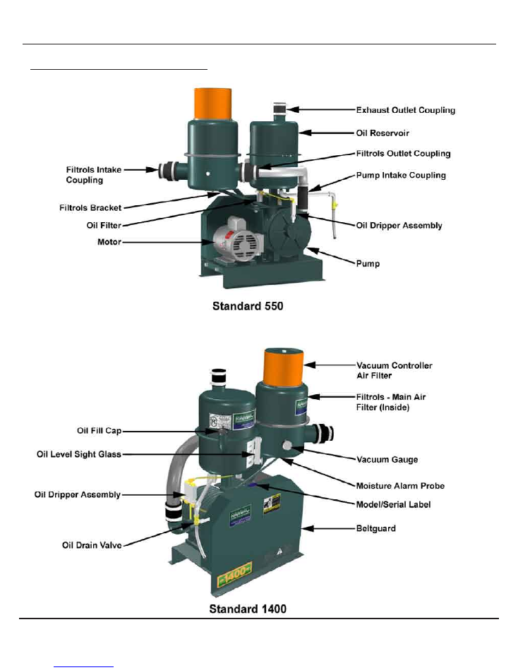
Standard Models Important Features
Page 3
STANDARD
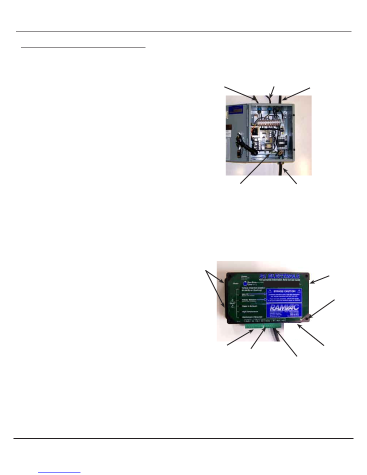
1 Phase Gray Box Electrols Upgrade
How to upgrade gray box Electrols to S1 Electrols on all
1 phase Standard models.
1. Secure disconnect.
2. Disconnect gray box Electrols.
a. Disconnect power source wires from L1, L2, and GND. Remove
cord grip and power source wires from gray box Electrols.
b. Disconnect motor wires from 2T1, 4T2, and motor ground.
Remove cord grip and motor wires from gray box Electrols.
c. Disconnect moisture alarm probe wires from P1 and P2.
Remove wires from cord grip.
d. Disconnect remote switch wires from R1, R2, and RL. Remove
wires from cord grip.
3. Discard gray box Electrols.
4. Install S1 Electrols using the 4 mounting holes.
5. Remove the cover screws and cover.
Note: There will be 2 wires under L1 screw and 2 wires under
GND screw.
6. Install cord grip and power source wires in side knockout on S1
Electrols.
a. Connect power source wires to L1, L2, and GND.
7. Install cord grip and motor wires to bottom knockout on S1 Electrols.
a. Connect motor wires to L1, M1 and GND.
8. Install cover using the screws previously removed.
9. If present, disconnect oil switch (spade terminals) from moisture
alarm cord.
a. Connect supplied extensions to wires coming from oil switch and
connect to terminals 1 and 2 on terminal plug “12DE34”.
10. Connect moisture alarm probe wires to terminals J and K on terminal
plug “56JK78”.
Note: If Electrols is part of a VSC or MPC, refer to “VSC or
MPC User Guide” for further installation instructions.
11.
Connect
low voltage remote switch wires to terminal plug FGH.
a. Connect switch wire to F.
b. Connect light wire to G.
c. Connect common wire to H.
Power Source Wires
L1, L2, GND
1 Phase Gray Box Electrols
Note: Gray Box Electrols have several variations
Remote Switch Wires
R1, R2, RL
Moisture Probe Wires
P1, P2
Motor Wires 2T1, 4T2
Motor Ground
S1 Electrols
Install Power
Source Wires
Install Motor Wires
Connect Remote
Switch to “FGH”
Connect Moisture
Alarm Probe to “JK”
S1 Electrols
Mounting Holes (4)
Motor Ground Lug
If Present,connect
oil switch to “1 2”
Cover Screws (4)
Page 4
STANDARD
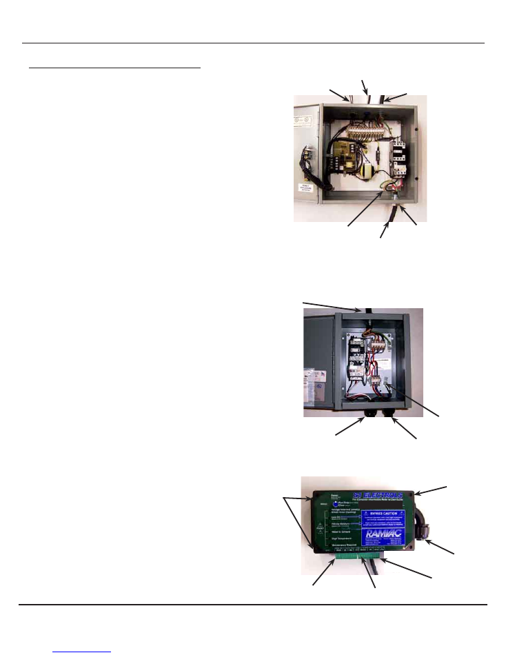
3 Phase Gray Box Electrols Upgrade
How to upgrade gray box Electrols to S1 Electrols on all
3 phase Standard models.
1. Secure Disconnect.
2. Remove items from gray box Electrols.
a. Disconnect power source wires from L1, L2, L3 and GND.
Remove cord grip and power source wires from gray box Electrols.
b. Disconnect motor wires from 2T1, 4T2, 6T3 and motor ground.
Remove cord grip and motor wires from gray box Electrols.
c. Disconnect moisture alarm probe wires from P1 and P2. Remove
wires from cord grip.
d. Disconnect remote switch wires from R1, R2, and RL. Remove
wires from cord grip.
3. Discard gray box Electrols.
4. Install motor starter.
5. Install S1 Electrols using the 4 mounting holes.
6. Install cord grip and power source wires into top knockout on motor
starter.
a. Connect power source wires to L1, L2, L3 and GND.
7. Install cord grip and motor wires into bottom knockout on motor
starter.
a. Connect motor wires to 2T1, 4T2, 6T3 and motor ground.
8. Install motor control wires marked C1, C2, C3, and GND from
S1 Electrols into bottom knockout on motor starter.
a. Connect wires C1, C2, C3, and GND to appropriate terminals.
9. If present, disconnect oil switch (spade terminals) from moisture
alarm cord.
a. Connect supplied extensions to wires coming from oil switch and
connect to terminals 1 and 2 on terminal plug “12DE34”.
10. Connect moisture alarm probe wires to terminals J and K on terminal
plug “56JK78”.
Note: If Electrols is part of a VSC or MPC, refer to “VSC or
MPC Manual” for further installation instructions.
11. Connect low voltage remote switch wires to terminal plug “FGH”.
a. Connect switch wire to F.
b. Connect light wire to G.
c. Connect common wire to H.
12. Perform
“ 3 Phase Motor Startup”
procedure.
S1 Electrols
Power Source Wires
L1, L2, L3, GND
3 Phase Gray Box Electrols
Note: Gray Box Electrols have several variations
Motor Wires 2T1, 4T2, 6T3
Motor Ground
Cord Grip
Remote Switch Wires
R1, R2, RL
Moisture Probe Wires
P1, P2
Motor Ground Lug
Motor Control Wires
C1, C2, C3, GND
Connect Remote
Switch to “FGH”
Connect Moisture
Alarm Probe to “JK”
S1 Electrols Mounting
Holes (4)
Motor Starter
Note: Motor Starter have several variations
Motor Wires 2T1, 4T2, 6T3
Motor Ground.
Motor Ground Lug
Power Source Wires
L1, L2, L3, GND
3 Ft Conduit with
motor control wires
If present, connect
Oil Switch to “1 2”
Cover Screws (4)

Page 5
NOTES
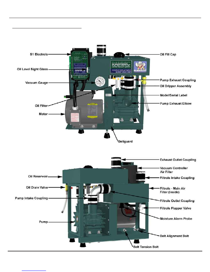
Page 6
BULLDOG
Bulldog Models Important Features
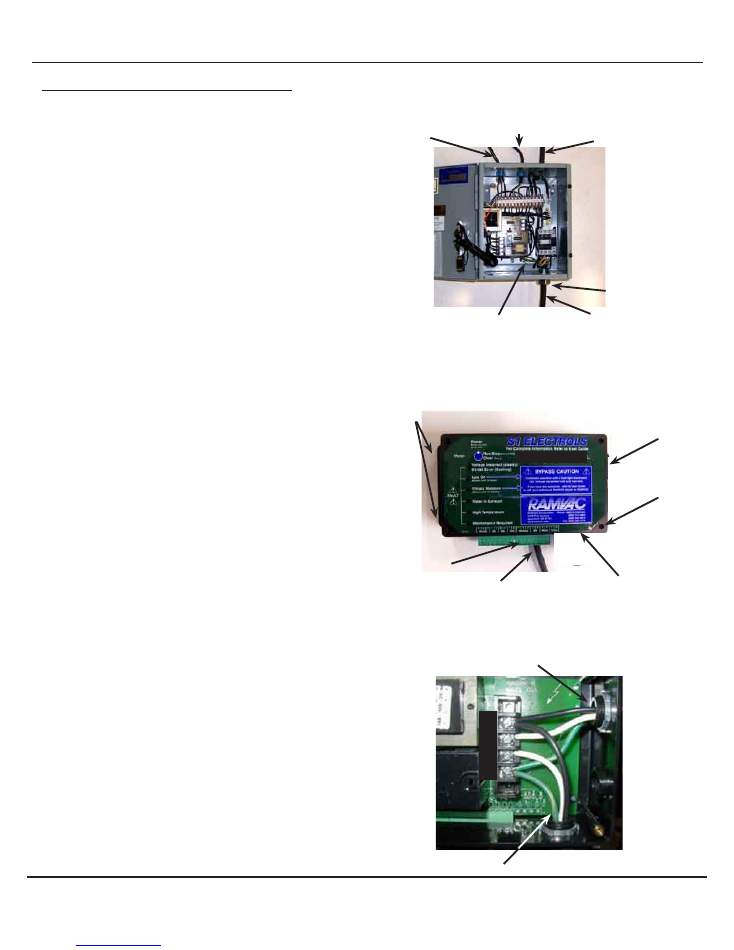
Page 7
BULLDOG
1 Phase Gray Box Electrols Upgrade
How to upgrade gray box Electrols to S1 Electrols on all
1 phase Bulldog models.
1. Secure Disconnect.
2. Remove items from gray box Electrols.
a. Disconnect power source wires from L1, L2, and GND. Remove
cord grip and power source wires from gray box Electrols.
b. Disconnect motor wires from 2T1, 4T2, and motor ground.
Remove cord grip and motor wires from gray box Electrols.
c. Disconnect moisture alarm probe wires from P1 and P2.
Remove wires from cord grip.
d. Disconnect remote switch wires from R1, R2, and RL.
Remove wires from cord grip.
3. Discard gray box Electrols.
4. Install S1 Electrols using the 4 mounting holes.
5. Remove the cover screws and cover.
Note: There will be 2 wires under L1 screw and 2 wires under
GND screw.
6. Install cord grip and power source wires in side knockout on
S1 Electrols.
a. Connect power source wires to L1, L2, and GND.
7. Install cord grip and motor wires to bottom knockout on S1 Electrols.
a. Connect motor wires to L1, M1 and GND.
8. Install cover using the screws previously removed.
9. Connect moisture alarm probe wires to terminals J and K on terminal
plug “56JK78”
Note: If Electrols is part of a VSC or MPC, refer to “VSC or
MPC Manual” for further installation instructions.
10. Connect low voltage remote switch:
a. Connect switch wire to F.
b. Connect light wire to G.
c. Connect common wire to H.
L1
L2
M1
GND
S1 Electrols
S1 Electrols
Remote Switch Wires
R1, R2, RL
Power Source Wires
L1, L2, GND
Moisture Probe Wires
P1, P2
Motor Wires
2T1, 4T2, Motor Ground
Cord Grip
Power Source Wires
Motor Wires
Install Power
Source Wires
Install Motor Wires
Connect Remote
Switch to “FGH”
Connect Moisture
Alarm Probe to “JK”
1 Phase Gray Box Electrols
Note: Gray Box Electrols have several variations
Motor Ground Lug
S1 Electrols Mounting
Holes (4)
Cover Screws (4)
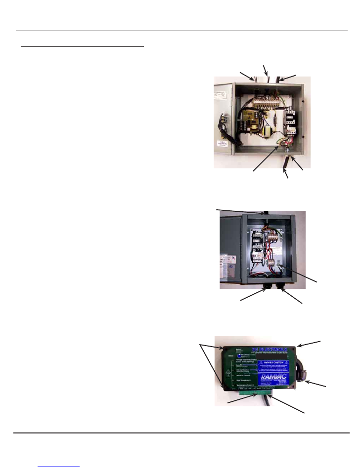
Page 8
BULLDOG
3 Phase Gray Box Electrols Upgrade
How to upgrade gray box Electrols to S1 Electrols on 3
phase Bulldog models.
1. Secure Disconnect.
2. Remove items from gray box electrols.
a. Disconnect power source wires from L1, L2, L3 and GND.
Remove cord grip and power source wires from gray box Electrols.
b. Disconnect motor wires from 2T1, 4T2, 6T3 and motor ground.
Remove cord grip and motor wires from gray box Electrols.
c. Disconnect moisture alarm Probe wires from P1 and P2.
Remove wires from cord grip.
d. Disconnect remote switch wires from R1, R2, and RL.
Remove wires from cord grip.
3. Discard gray box Electrols.
4. Install motor starter.
5. Install S1 Electrols using the 4 mounting holes.
6. Install cord grip and power source wires into top knockout on
motor starter.
a. Connect power wires to L1, L2, L3 and GND.
Note: There will be 2 wires in the motor ground lug.
7. Install cord grip and motor wires into bottom knockout on motor
starter.
a. Connect motor wires to 2T1, 4T2, 6T3 and motor ground.
8. Install cord grip and control wires marked C1, C2, C3, and GND from
S1 Electrols
into bottom knockout on motor starter.
a. Connect wires C1, C2, C3, and GND to appropriate terminals.
9. Connect moisture alarm probe wires to terminals J and K on terminal
plug “56JK78”.
Note: If Electrols is part of a VSC or MPC, refer to “VSC or
MPC Manual” for further installation instructions.
10. Connect remote switch wires to terminal plug “FGH”.
a. Connect switch wire to F.
b. Connect light wire to G.
c. Connect common wire to H.
11. Perform
“ 3 Phase Motor Startup”
procedure.
Connect Low Voltage
Remote Switch to “FGH”
Connect Moisture
Alarm Probe to “JK”
S1 Electrols
Power Source Wires
L1, L2, L3, GND
3 Phase Gray Box Electrols
Note: Gray Box Electrols have several variations
Motor Wires 2T1, 4T2, 6T3
Motor Ground
Cord Grip
Remote Switch Wires
R1, R2, RL
Moisture Probe Wires
P1, P2
Motor Ground Lug
Motor Starter
Note: Motor Starter have several variations
Motor Wires 2T1, 4T2, 6T3
Motor Ground
Motor Control Wires
C1, C2, C3, GND
Motor Ground Lug
Power Source Wires
L1, L2, L3, GND
3 Ft Conduit with
motor control wires
S1 Electrols Mounting
Holes (4)
Cover Screws (4)

Page 9
NOTES
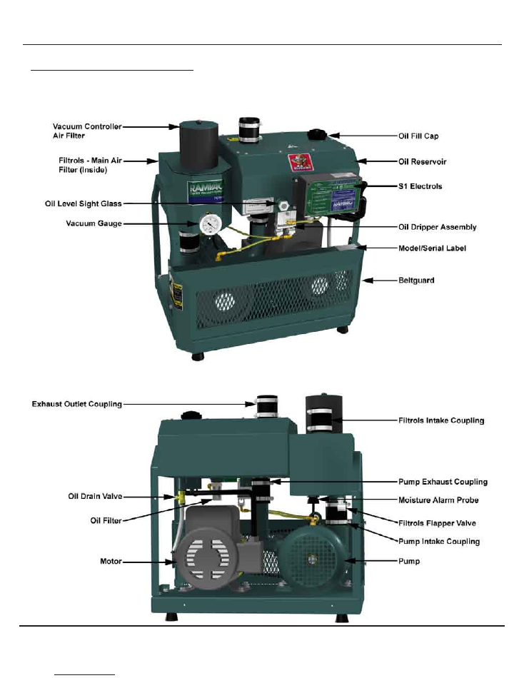
Page 10
BISON
Bison Models Important Features
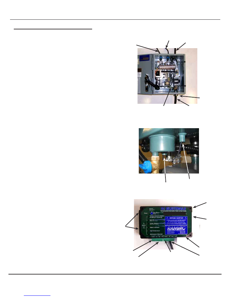
1 Phase Gray Box Electrols Upgrade
How to upgrade gray box Electrols to S1 Electrols on
1 phase Bison models.
1. Secure Disconnect.
2. Remove items from gray box Electrols.
a. Disconnect power source wires from L1, L2, and GND. Remove
cord grip and power source wires from gray box Electrols.
b. Disconnect motor wires from 2T1, 4T2, and motor ground.
Remove cord grip and motor wires from gray box Electrols.
c. Disconnect moisture alarm probe wires from P1 and P2. Remove
wires from cord grip.
d. Remove remote switch wires from R1, R2, and RL. Remove wires
from cord grip.
3. Discard gray box Electrols.
4. Install S1 Electrols using the 4 mounting holes.
5. Remove the cover screws and cover.
Note: There will be 2 wires under L1 screw and 2 wires under
GND screw.
6. Install cord grip and power source wires in side knockout on S1 Electrols.
a. Connect power wires to L1, L2, and Gnd.
7. Install cord grip and motor wires to bottom knockout on S1 Electrols
a. Connect motor wires to L1, M1, and Gnd.
8. Install cover using the screws previously removed.
9. Disconnect oil switch and water switch (2 spade terminals)
from moisture alarm cord.
a. Cut spade terminal ends from switch wires.
b. Install the supplied spade terminals on each of the 4 wire ends.
c. Connect supplied extensions to wires and connect to terminals.
i. Connect the oil switch wires to terminals 1 and 2 on terminal
plug “12DE34”.
ii. Connect the water in exhaust switch wires to terminals 3 and 4
on terminal plug “12DE34”.
10. Connect moisture alarm probe wires to terminals J and K on terminal
plug “56JK78”.
Note: If Electrols is part of a VSC or MPC, refer to “VSC or
MPC Manual” for further installation instructions.
11. Connect remote switch wires to terminal plug “FGH”.
a. Connect switch wire to F.
b. Connect light wire to G.
c. Connect common wire to H.
Page 11
BISON
1 Phase Gray Box Electrols
Note: Gray Box Electrols have several variations
Remote Switch Wires
R1, R2, RL
Power Source Wires
L1, L2, GND
Moisture Probe Wires
P1, P2
Motor Wires 2T1, 4T2
Motor Ground
Cord Grip
Install Power
Source Wires
Install Motor
Wires
Connect Remote
Switch to “FGH”
Connect Moisture
Alarm Probe to “JK”
S1 Electrols
Connect Water in
Exhaust to “3 4”
Connect Oil
Switch to “1 2”
Bison Reservoir Switches
Oil Switch
Water in Exhaust Switch
Motor Ground Lug
S1 Electrols
Mounting Holes (4)
Cover Screws (4)
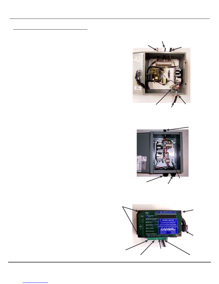
Page 12
BISON
3 Phase Gray Box Electrols Upgrade
How to upgrade gray box Electrols to S1 Electrols on 3
phase Bison models.
1. Secure Disconnect.
2. Remove items from gray box Electrols.
a. Disconnect power wires from L1, L2, L3 and GND. Remove cord
grip and power source wires from gray box Electrols.
b. Disconnect motor wires from 2T1, 4T2, or 6T3 and motor ground.
Remove cord grip and motor wires from gray box Electrols.
c. Disconnect moisture alarm probe wires from P1 and P2.
Remove wires from cord grip.
d. Disconnect remote switch wires from R1, R2, and RL.
Remove wires from cord grip.
3. Discard gray box Electrols.
4. Install motor starter.
5. Install S1 Electrols using the 4 mounting holes.
6. Install cord grip and power source wires into top knockout on motor starter.
a. Connect power wires to L1, L2, L3 and GND.
Note: There will be 2 wires in the motor ground lug.
7. Install cord grip and motor wires into bottom knockout on motor starter.
a. Connect motor wires to 2T1, 4T2, 6T3 and motor ground.
8. Install cord grip and control wires marked C1, C2, C3, and GND from
S1 Electrols into bottom knockout on motor starter.
a. Connect wires C1, C2, C3, and GND to appropriate terminals.
9. Disconnect oil switch and water switch (spade terminals)
from moisture alarm cord.
a. Cut spade terminal ends from switch wires.
b. Install the supplied spade terminals on each of the 4 wire ends.
c. Connect supplied extensions to wires and connect to terminals.
Note: See Bison Reservoir Swtches illustration on previous
page for specific locations.
i. Connect the oil switch wires to terminals 1 and 2 on terminal
plug “12DE34”.
ii. Connect the water in exhaust switch wires to terminals 3
and 4 on terminal plug “12DE34”.
10. Connect moisture alarm probe wires to terminals J and K on terminal
plug “56JK78”.
Note: If Electrols is part of a VSC or MPC, refer to “VSC or
MPC Manual” for further installation instructions.
11. Connect remote witch wires to terminal plug “FGH”.
a. Connect switch wire to F.
b. Connect light wire to G.
c. Connect common wire to H.
12. Perform
“ 3 Phase Motor Startup”
procedure.
Connect Remote
Switch to “FGH”
Connect Moisture
Alarm Probe to “JK”
S1 Electrols
Power Source Wires
L1, L2, L3, GND
3 Phase Gray Box Electrols
Note: Gray Box Electrols have several variations
Motor Wires
2T1, 4T2, & 6T3
Cord Grip
Remote Switch Wires
R1, R2, and RL
Moisture Probe Wires
P1, P2
Motor Ground Lug
Motor Starter
Motor Wires 2T1, 4T2,
6T3, Motor Ground
Motor Control Wires
C1, C2, C3, GND
Motor Ground Lug
Power Source Wires
L1, L2, L3, GND
3 Ft Conduit with
motor control wires
S1 Electrols Mounting
Holes (4)
Connect Oil
Switch to “1 2”
Connect Water in
Exhaust to “3 4”
Cover Screws (4)

Page 13
NOTES
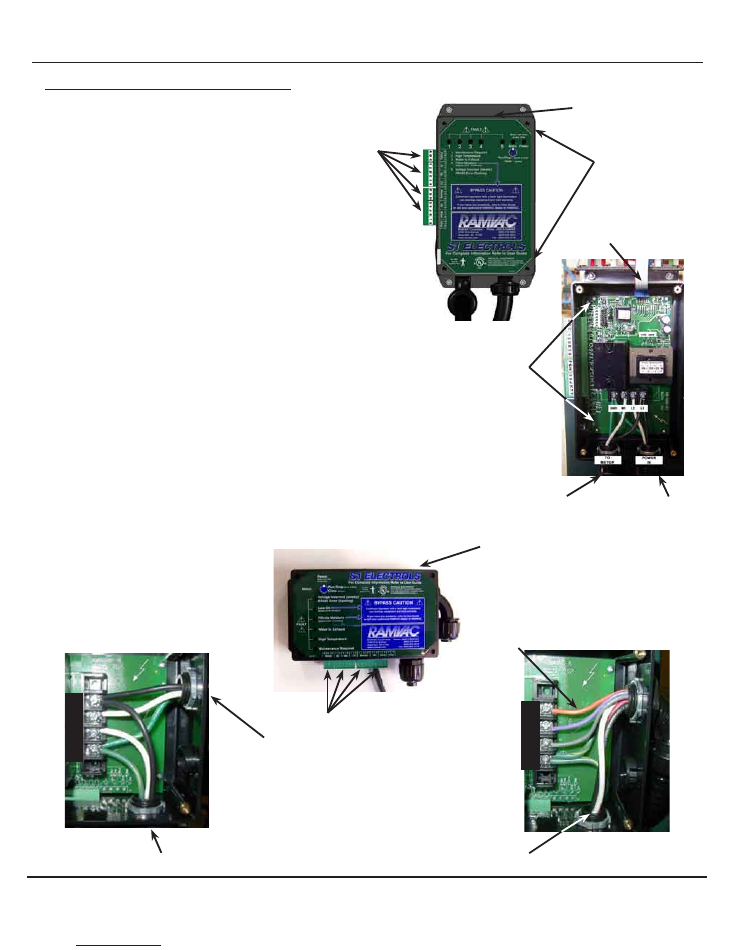
Page 14
S1 ELECTROLS PC BOARD REPLACEMENT
S1 Electrols PC Board Replacement
How to replace the S1 Electrols PC board on all models.
1. Secure Disconnect.
2. Remove original Electrical Specifications decal from top of S1
Electrols.
3. Apply new Electrical Specifications decal to top of S1 Electrols.
Note orientation and position of termnal plugs for re-installation
4.
Remove terminal plugs attached to S1 Electrols.
5. Remove cover screws and open cover.
Note orientation of power source and motor wires for proper
connection.
6. Disconect power source and motor wires from terminal strip.
7. Remove corner screws on the pc board. Remove pc board.
8. Install replacement pc board in S1 Electrols box and secure it with
corner screws.
9. With proper orientation connect power source and motor wires to
terminal strip.
10. Install cover using screws previously removed.
11. With proper orientation, insert terminal plugs into S1 Electrols.
L1
L2
M1
GND
Bison Model S1 Electrols
Terminal plugs
Electrical Specification Label
Bulldog Model S1 Electrols
Ribbon cable
Corner screws (4)
(corner of PC board)
Power Source Wires
Motor Wires
Terminal plugs
Electrical Specification Label
3 Phase Wiring
1 Phase Wiring
L1
L2
M1
GND
Motor Wires
Power Source Wires
Motor Control Wires
Motor Wires
Remove Cover Screws (4)
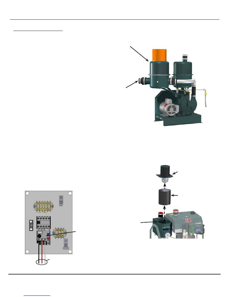
Page 15
3 PHASE MOTOR START-UP
3 Phase Motor Start-up
How to properly start a 3 phase unit the first time or after
changes to motor, motor starter or Electrols.
1. Turn power on at disconnect.
Caution: Pump has 50% chance of rotating backwards.
DO NOT ALLOW debris to enter pump.
2. Check for correct pump rotation:
a.
Standard Models:
i. Loosen Filtrols intake coupling and remove line.
ii. Place hand by Filtrols intake to determine airflow.
b.
Bulldog and Bison Models:
i. Remove vacuum controller and main air filter from power unit.
ii. Place hand in Filtrols close to pump inlet to determine airflow.
3. Run vacuum unit long enough to determine airflow direction, then
turn pump off.
a. If air blows out of inlet pipe:
i. Reverse any two motor wires on motor overload.
ii. Repeat step 3.
b. If air sucks into inlet pipe:
i. Clean any oil or debris out of Filtrols.
4. Complete 3 phase motor start-up
a.
Standard Models:
Reinstall Filtrols inlet line
b.
Bulldog and Bison Models:
Reinstall main air filter and
vacuum controller.
Vacuum Controller
Main Air Filter
Filtrols - (Main Air
Filter inside)
Note: Contents inside
motor starters will vary.
For simplicity, not all motor
starter wiring is shown.
Switch any two of these wires to
reverse rotation.
Standard Models
Bison and Bulldog Models
Motor Starter
Filtrols Intake
Coupling
Motor Overload
Filtrols

3100 First Avenue
Spearfish SD 57783 USA
Web: ramvac.com
Phone:
Fax:
1-800-5-RAMVAC
1-605-642-4614
1-605-642-3776
SOF_7.2.3-01-139.doc
Effective Date: 25-Oct-05
Page 16 of 16
NOTES