Full Text Searchable PDF User Manual
QT INSTRUCTION
MANUAL
PLEASE READ BEFORE USE
Distributed by Qpod Motor Company
Tel: 01404 850545 Fax: 01404 851110
www.qpod.co.uk

2
Contents
Pg 3
Servicing and Warranty
Pg 4
Serial Numbers / Vehicle Keys / Vehicle Ignition
Pg 5
Vehicle Instruments and Controls
Pg 6
Instrument Panel
Pg 7
Instrument Panel Warning Lights / Lighting Control /
Indicators / Horn / Rear Fog Lamp Control
Pg 8
Centre Console Switches / Heater Temperature Control
Tap / Seat Belts / Manual Gear Lever
Pg 9
Foot Pedal Controls / Handbrake / Locking Fuel Cap
Pg 10
The Bonnet Section / Under The Bonnet / Under The
Boot
Pg 11
First Service Return Form
Pg 12
General Specifications / Servicing Schedule

3
-
-
-
-
-
-
Servicing and warranty
•
•
•
•
•
•
The QT has been designed primarily as a fun vehicle to travel relatively
short distances on or off road. No warranty or representation is made
by QMC as to the fitness for any specific use of any v unless
expressly set out in writing and signed by a director. Whilst members
of staff will answer any questions in good faith, if it is a customer’s
intention to rely on any statements given by staff in deciding to buy a
vehicle, then it is incumbent on the customer to obtain such statement
in writing from QMC, signed by a director. QMC will not normally be in
a position to form a view on whether a vehicle is suitable for a
particular use linked to the specific and particular needs of an
individual customer, but will only be able to answer questions about
the features of the vehicles.
The warranty is only valid with proof of first service at an authorised
service point giving the details of the owner, mileage, registration and
chassis number of the vehicle on the First Service Return Form and
returned to QMC.
The basic warranty covers parts and labour for a period of 2 years
from the date of production. However, if a vehicle is used for
commercial purposes, (e.g. self drive hire, advertising/promotions
vehicle or as a taxi) the warranty covers parts only, nd only for 6
months from registration.
The warranty does not include breakdown recovery, collection or
delivery, only parts and labour whilst the vehicle is at an authorised
service workshop.
We reserve the right to replace or repair defective parts at our
discretion and to require that defective parts that are replaced are
returned to us.
The Warranty is invalidated if:
The vehicle is worked on by any workshop not previously approved
in writing by Secma or QMC.
If the original specifications of the vehicle are modified in any way.
If non-genuine spare parts are used.
If the vehicle is subject to negligent or unreasonable use or is
overloaded in any way.
If the damage is due to the inexperience or carelessness of the
driver or incorrect or inappropriate maintenance.
If the vehicle is used for competition, self drive hire or as a taxi.
The Warranty does not extend to normal wear and tear, cables, tyres,
batteries, bulbs, etc towing costs or costs consequent upon the
breakdown of the vehicle.
4
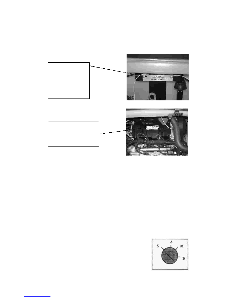
Serial Numbers
Vehicle Keys
Vehicle Ignition
S
A
M
D
Chassis
Number
Engine Number
You will be supplied with 2 x Ignition Keys, 2 x Petrol Cap Keys and
2 x Engine Compartment Lid Keys.
The Ignition Key operates as follows:
– Parking position and Steering Lock
– Ignition Off
– Engine Running
– Engine Start
The
is located
on a plate in the
engine
compartment. It is
also stamped under
the rear driver’s
side wheel arch.
The
is
located on the top of the
engine and is also
stamped onto the front
of the engine casing.
5
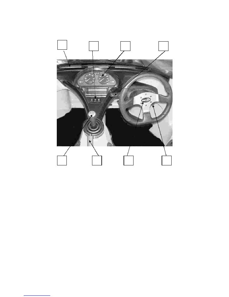
Vehicle Instruments and Controls
1 – Windscreen Demisting Vents
2 – Centre Console Switches – Hazard Warning Lights, Windscreen
Wiper and Washers.
3 – Instrument Panel
4 – Lighting Control, Fog Lamp, Horn and Indicators.
5 – Gear Lever
6 – Handbrake
7 – Steering Wheel
8 – Steering Lock and Ignition
1
2
3
4
8
7
6
5
6
1
2
3
5
9
7
6
4
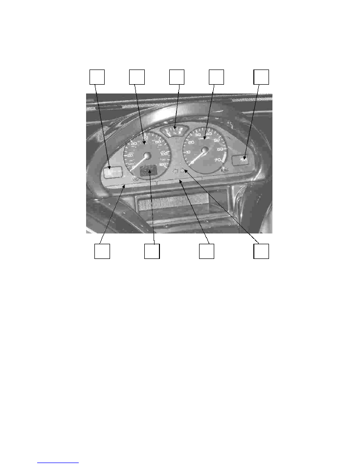
Instrument Panel
1 – Engine Coolant Temperature Warning Light
2 – Speedometer
3 – Fuel Gauge
4 – Rev Counter
5 – Oil Pressure Warning Light
6 – High/Low Headlight Beam and Rear Fog Lamp
7 – Trip Recorder and Service Indicator
8 – Battery Charge and Handbrake Warning Lights
9 – Indicator Left and Right
8
7
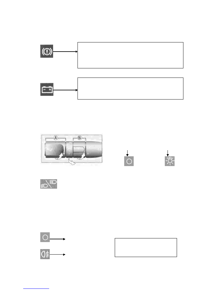
Instrument Panel Warning Lights
Lighting Control
Fig 1:
Dipped/Main Beam Headlights:
Indicators:
downwards
upwards
Horn:
Rear Fog Lamp Control:
Handbrake and Brake Fluid Level Warning Light:
Battery Charge Warning Light:
Front Lights:
Pull stalk towards you to
change the setting.
To Indicate LEFT move the stalk
and to
indicate RIGHT move the stalk
.
Press the end of the stalk.
If fitted (optional extra) operate using ring B (Fig 1)
Fog Lamp OFF
Fog Lamp ON
If
lit, it indicates that either the handbrake is applied or not
been fully released OR the Brake Fluid level has dropped
dramatically (the light will remain lit even though the
handbrake has definitely been released).
If lit, it indicates that
either there is a fault in the operation of the battery
charging circuit OR the battery or starter terminals are
loose OR there is an Alternator fault.
To operate, turn ring A, (Fig 1)
Lights Off
Side Lights On
This operates with the Dipped
and Main Beam Lights.
8
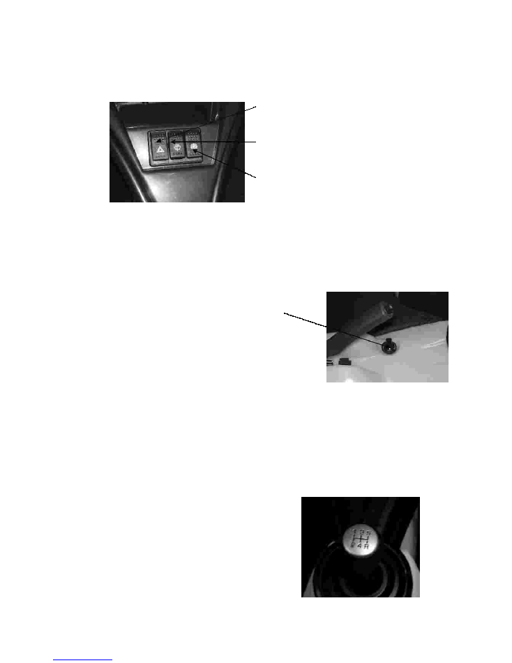
Centre Console Switches
Heater Temperature Control Tap
Seat Belts
Manual Gear Lever
Seat Belts must be worn at all times by the driver and passenger when in the
vehicle.
Make sure that the Seat Belt buckle is firmly latched together before driving off in
the vehicle.
Hazard Warning Lights
Windscreen Wiper and Washers. (To
activate the washers press and hold the
switch beyond the first click).
Heater Fan Switch. First click = Low
setting. Second click = High setting.
The temperature for the heater is controlled
by turning the tap whish is situated under
the handbrake.
Turn Clockwise for warm air (plus Heater
Fan ON)
Turn Anti-clockwise for cold air (plus
Heater Fan ON)
The gear positions are indicated on the gear
lever knob.
Reverse gear can only be engaged from
Neutral when the vehicle is stationary with
the engine idling.
•
•
9
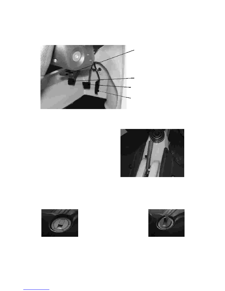
Foot Pedal Controls
Handbrake
Locking Fuel Cap
Pedal Adjustment Lever
(To adjust the pedals backwards and
forwards, pull the lever down and
either pull or push it to bring the
pedals closer or further away.)
Clutch Pedal
Brake Pedal
Accelerator Pedal
To apply the handbrake once you
are in a parked position, pull the
lever UP.
To release the handbrake, press
the button on the end and push
the lever DOWN.
The vehicle has a hinged locking
fuel cap in the middle of the
bonnet. The key hole of the cap
is located under the flap marked
‘lift’. Turn the key 90
0
clockwise
to open.

10
The Bonnet Section
Under The Bonnet
Under The Boot
Note –
Engine Oil Level ‘Dip Stick’
Engine Oil Filling Point
Radiator Cap
Note –
The bonnet panel is secured by four
quick release pins. To remove the
bonnet panel, all of the pins must be
removed by turning them 90
0
anti-
clockwise with a screw-driver. To
replace the bonnet; push down the
pins and turn back 90
0
clockwise with
a screw-driver.
The same pins fix down the
boot corners.
1 – Battery
2 – Washer Bottle
3 – Fuse Box – (see below)
15 amp
10 amp
10 amp
7.5 amp
7.5 amp
10 amp
1 amp
7.5 amp
- Main feed to ECU
- Rear Lights (Fog and Reverse)
- Headlights
- Indicators, wiper and washer
- Heater Fan
- Ignition Circuit
- Dash Warning Lights
- Side Lights
; Check
the Oil regularly and top up when
required.
; Check water level
regularly and top up with distilled water
when required.
Only check the levels when the
engine is cold and not running.

11
FIRST SERVICE RETURN FORM
Returned to -
Qpod Motor Company
Fenny Bridges, Honiton, EX14 3BG
Vehicle type:
Vehicle registration :
Chassis number:
Customer name:
Customer address:
Date of 1st Service:
Speedo Reading :
Name and Telephone Number of Service Site :
Service Engineer
Sign –
Print -
Comments :

12
QT - General Specifications
Dimensions
Weight
Length
Width
Height
Fuel
Fuel type
Fuel tank capacity
Fuel consumption (average)
Oil
Engine oil
Engine oil capacity
Gearbox oil
Tyres
Tyre size
Tyre pressure
Service Schedule
First Service at 600 miles (1000 km)
Service at 3000 miles (5000km) and every 3000 miles thereafter
Every 6000 miles (10000km)
Every 12000 miles (20000km)
Every 50000 miles (80000km)
- 398kg,
- 240cm,
- 140cm,
- 110cm
- 95 octane min.
- 22litres
- Approx. 60 mpg
– Multi-grade SAE 15W40 - 15W50 - 10W40
- 1.3 litres
- Not applicable (designed to last the life of the gearbox)
- 175/60 13
- 1.5 to 1.8 bar front and rear
Oil change (1.3 litres including filter)
Change oil filter
Check liquid levels of coolant and brake systems
Check torque of wheel nuts
Check clearances on the brake and clutch pedals
Check condition of brake pads
Check adjustment of hand brake cable
Check lights and headlight adjustment
Road test
As per 600 mile service, also
Clean air filter
Change fuel filter
Change air filter
Change spark plugs
Change cam belt
•
•
•
•
•
•
•
•
•
•
•
•
•
•
•