Full Text Searchable PDF User Manual
PICO MACOM INC.
12500 Foothill Blvd. • Lakeview Terrace, CA 91342 • (818) 897-0028 • (800) 421-6511 • FAX (818) 834-7197
Doc. No. OM2116N-1 REV. F
Date: 12/06/96
Installation
And
Operation
Manual
P/N: 911028
AUDIO &
VIDEO
MODULATOR
P C M 5 5
NTSC
PICO MACOM INC.
12500 Foothill Blvd. • Lakeview Terrace, CA 91342 • (818) 897-0028 • (800) 421-6511 • FAX (818) 834-7197
S A F E G U A R D S
Important Information
Product Inspection
Inspect the equipment for shipping damage.
Should any damage be discovered, immediately file
a claim with the carrier.
Important
Safety Instructions
To ensure proper installation and operation,
take a moment to read this guide before proceeding
with the installation. If you have any questions or
comments about the
PCM55
modulator, please
contact your dealer or have him contact the
PICO
MACOM
Service Center at the phone numbers at
the bottom of the page.
WARNING:
TO REDUCE THE RISK OF FIRE OR ELECTRIC SHOCK, DO NOT
EXPOSE THIS APPLIANCE TO RAIN OR MOISTURE. DO NOT OPEN THE
CABINET, REFER SERVICING TO QUALIFIED PERSONNEL ONLY.
CAUTION:
TO PREVENT ELECTRIC SHOCK DO NOT USE THIS (POLARIZED) PLUG
WITH AN EXTENSION CORD RECEPTACLE OR OTHER OUTLET UN
LESS THE BLADES CAN BE FULLY INSERTED TO PREVENT BLADE
EXPOSURE.
ATTENCION
: POUR PREVENIR LES CHOCS ELECTRIQUES, NE PAS UTILISER CETTE
FICHE POLARISEE AVEC UN PROLONGATEUR, UNE PRISE DE COURANT
OU UNE AUTRE SORTIE DE COURANT, SAUF SI LES LAMES PEUVENT
ETRE INSEREES A FOND SANS EN LAISSER AUCUNE PARTIE A
DECOUVERT.
1. Read Instructions -
All safety and operating instructions
should be read before the appliance is operated.
2. Retain Instructions -
The safety and operating instructions
should be retained for future reference.
3. Heed Warnings -
All warnings on the appliance should be
adhered to.
4. Follow Instructions -
All operating and user instructions
should be followed.
5. Cleaning -
Unplug this appliance from the wall outlet before
cleaning. Use a damp cloth for cleaning. Do not use liquid
cleaners or aerosol cleansers.
6. Do Not Use Attachments -
not recommended by the manu-
facturer or they may cause hazards.
7. Water and Moisture -
Do not use this product near water - for
example, near a bathtub, washbowl, kitchen sink, laundry tub, in
a wet basement, or near a swimming pool - and the like.
8. Accessories -
Do not place this product on an unstable cart,
stand, tripod, bracket, or table. The product may fall, causing
serious injury to a child or adult, and serious damage to the
appliance.
9. Ventilation -
This video product should never be placed near
or over a radiator or heat register. This video product should not
be placed in a built-in installation such as a bookcase or rack unless
proper ventilation is provided or the manufacturer’s instructions
have been adhered to. Any slots or opening in the cabinet are
provided for ventilation. To ensure reliable operation of the video
product and to protect it from overheating, these openings must
not be blocked or covered. The openings should never be blocked
by placing the product on a bed, sofa, rug, or other similar surface.
The lightning flash with arrowhead symbol, within an equilateral
triangle, is intended to alert the user to the presence of uninsulated
"dangerous voltage" within the product's enclosure that may be
of sufficient magnitude to constitute a risk of electric shock to
persons.
The exclamation point within an equilateral triangle is intended
to alert the user to the presence of important operating and
maintenance (servicing) instructions in the literature accompa-
nying the appliance.
1
!
CAUTION
RISK OF ELECTRIC SHOCK
DO NOT OPEN
PICO MACOM INC.
12500 Foothill Blvd. • Lakeview Terrace, CA 91342 • (818) 897-0028 • (800) 421-6511 • FAX (818) 834-7197
10. Grounding or Polarization -
This video product is equipped
with either a three prong plug for 110 VAC use or a two prong
flat blade 220 volt type plug. Each type is to be inserted into
only the type of receptacle for which they specifically designed
.
Do not
cut off the round grounding pin in order to be able to
fit into a two prong receptacle as this could cause injury and will
void the warranty.
11. Power Sources -
This product should be operated only from
the type of power source indicated on the marking label. If you
are not sure of the type of power supplied to your home, consult
your appliance dealer or local power company.
12. Power-cord Protection -
Power-supply cords should be
routed so they are not likely to be walked on or pinched by items
placed upon or against them. Pay particular attention to cords and
plugs, convenience receptacles, and the point where they exit
from the appliance.
13. Lightning -
For added protection for this product during a
lightning storm, or when it is left unattended and unused for long
periods of time, unplug it from the wall outlet.
14. Power Lines -
An outside antenna system should not be
located in the vicinity of overhead power lines, other electric light
or power circuits, where it can fall into such power lines or
circuits. When installing an outside antenna system, extreme care
should be taken to keep from touching such power lines or circuits
as contact with them may be fatal.
15. Overloading -
Do not overload wall outlets and extension
cords as this can result in risk of fire or electric shock.
16. Object and Liquid Entry -
Never push objects of any kind
into this product through openings as they may touch dangerous
voltage points or short-out parts that could result in a fire or
electric shock. Never spill liquid of any kind on the product.
17. Servicing -
Do not attempt to service this product yourself as
opening or removing covers may expose you to dangerous
voltage or other hazards. Refer all servicing to qualified service
personnel.
18. Damage Requiring Service -
Unplug this product from the
wall outlet and refer servicing to qualified service personnel
under the following conditions:
a. When the power-supply cord or plug is damaged.
b. If liquid has been spilled, or objects have fallen into the
product.
c. If the product has been exposed to rain or water.
d. If the product does not operate normally by following the
operating instruction. Adjust only those controls that are covered
by the operating instructions. An improper adjustment may result
in damage and will often require extensive work by a qualified
technician to restore the product to its normal operation.
e. If the product has been dropped or the cabinet has been
damaged.
f. When the product exhibits a distinct change in performance -
this indicates a need for service.
19. Replacement Parts -
When replacement parts are required,
be sure the service technician has used replacement parts specified
by the manufacturer or have the same characteristics as the
original parts. Unauthorized substitutes may result in fire, electric
shock or other hazards.
20. Safety Check -
Upon completion of any service or repairs to
this product, ask the service technician to perform safety checks to
determine that the product is in proper operating conditions.
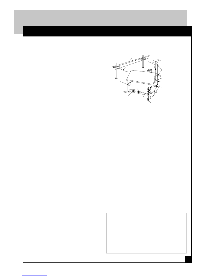
21. Outdoor Antenna Grounding -
Before attempting to install
this product, be sure the antenna or cable system is grounded so as
to provide some protection against voltage surges and built-up
static charges.
a. Use No.10 AWG (5.3mm ) copper, No.8 AWG (8.4mm
(aluminum, No.7 AWG (10mm ) copper-clad steel or bronze wire
or larger, as ground wire.
b. Secure antenna lead-in and ground wires to house with stand-
off insulators spaced from 4 feet (1.22m) to 6 feet (1.83m) apart.
c. Mount antenna discharge unit as close as possible to where lead-
in enters house.
d. A driven rod may be used as the grounding electrode where
other types of electrode systems do not exist. Refer to the National
Electrical Code, ANSI/NFPA 70-1984 for information.
e. Use jumper wire not smaller than No.6 AWG (13.3mm ) copper
or equivalent, when a separate antenna grounding electrode is
used.
Important Information
S A F E G U A R D S
NOTE TO THE CATV SYSTEM INSTALLER:
THIS REMINDER IS PROVIDED TO CALL THE CATV
SYSTEM INSTALLER’S ATTENTION TO ARTICLE 820 -
22 OF THE NEC THAT PROVIDES GUIDELINES FOR
PROPER GROUNDING AND, IN PARTICULAR, SPECI-
FIES THAT THE CABLE GROUND SHALL BE CON-
NECTED TO THE GROUNDING SYSTEM OF THE BUILD-
ING, AS CLOSE TO THE POINT OF CABLE ENTRY AS
PRACTICAL.
2
STANDOFF
INSULATORS
b
MAST
ANTENNA
LEAD-IN WIRE
c
GROUND WIRE
TO EXTERNAL ANTENNA
TERMINALS OF PRODUCT
ANTENNA
DISCHARGE UNIT
GROUND CLAMPS
OPTIONAL ANTENNA GROUNDING ELECTRODE
DRIVEN 8 FEET (2.44M) INTO THE EARTH
IF REQUIRED BY LOCAL CODES. SEE NEC
SECTION 810 - 21(f).
BONDING JUMPER
d
GROUND CLAMPS
POWER SERVICE GROUNDING
ELECTRODE SYSTEM
(e.g. interior metal water pipe)
SERVICE
ENTRANCE
EQUIPMENT
SERVICE ENTRANCE
CONDUCTORS
GROUND CLAMP
POW
ER L
INES
EXAMPLE OF ANTENNA GROUNDING ACCORDING TO
NATIONAL ELECTRICAL CODE INSTRUCTIONS CONTAINED
IN ARTICLE 810 - "RADIO AND TELEVISION
EQUIPMENT"

PICO MACOM INC.
12500 Foothill Blvd. • Lakeview Terrace, CA 91342 • (818) 897-0028 • (800) 421-6511 • FAX (818) 834-7197
D E S C R I P T I O N S
3
Description and Specifications
Features
• All Band Design: VHF (2-13),
Midband (A-I), Superband (J-W)
• Excellent audio and video linearity
• Separate modulation and RF level controls
• 110 VAC version UL and CSA Listed
• Power On Front Panel Indicator
Specifications
RF
Output Channels
....... 2-36, STD, IRC, HRC and
FCC docket 21006 offsets
Frequency Range
............................ 54-300 MHz
Output Level
..................................... + 55 dBmv
Output Adjustment Range
........................ 12 dB
Spurious Output
....... -60 dB @ 55 dBmv output
(A/V carrier -15 dB)
Sideband Filter Response @ 87% Modulation
Frequency
Low Mid & High Superband
MHz
Band Band J - W
Fv -4.5
-60dB
-60dB
-55dB
Fv -3.0
-45dB
-40dB
-30dB
Fv -1.5
-40dB
-40dB
-20dB
Fs +1.0
-45dB
-40dB
-25dB
Fs +3.0
-45dB
-40dB
-28dB
Fs +4.5
-60dB
-60dB
-55dB
Frequency Stability
...............................
±
10kHz,
±
5 kHz Aeronautical
(conforms to FCC requirements)
Offsets Pre-set
................. +12.5 kHz or +25 kHz
on FCC specified channels
(Special Offsets Available)
Audio/Video Ratio
...................... -7 dB to -18 dB
(preset @ -15 dB)
Video
Input Level
........ 0.5 V p-p minimum for 87.5%
modulation
Input Type
........ Composite Video, negative sync.
Visual C/N
.......................... 58 dB @ 4 MHz BW
Hum and Noise
........ -55 dB @ 87.5% modulation
Frequency Response
....
±
1.5 dB 30 Hz to 4 MHz
Differential Gain
............................... less than 5%
Differential Phase
............................... less than 5
°
Group Delay
.. 75 nsec (conforms to FCC require-
ments)
Audio
Input Impedance
................ 600 ohms unbalanced
Baseband input
..... 0.5 Vp-p for 25 kHz deviation
Pre-emphasis
.............................. 75 microseconds
Flatness
.................... 1.5 dB max 50 Hz to 15 kHz
Frequency Response
................... 15 Hz to 15 kHz
Subcarrier Frequency
.......... +4.5 MHz
±
10 kHz
General
AC Power
........................ 108 to 125 VAC, 60 Hz
220VAC, 60 Hz
Weight
.................................................. 2.5 Pounds
Dimensions
......................... 19"W x 1.75"H x 3"D
Operating Temperature
........ 0 to 50 Degrees C
The Pico Macom Inc. PCM55 modulator
provides a modulated visual and aural RF carrier
output on any single lowband, midband, or
superband channel.An improved manufacturing
process and high quality components assure years
of trouble free operation. Multi-section LC
filtering has been added to make the unit adjacent
Specifications subject to change without notice
channel compatible. This unit supplies high quality
video, color, and sound signals on any unused
channel within a closed circuit MATV or SMATV
system. The modulator is shipped with all internal
adjustments preset and is provided with separate
external modulation and RF level controls.
PICO MACOM INC.
12500 Foothill Blvd. • Lakeview Terrace, CA 91342 • (818) 897-0028 • (800) 421-6511 • FAX (818) 834-7197
P A N E L S
4
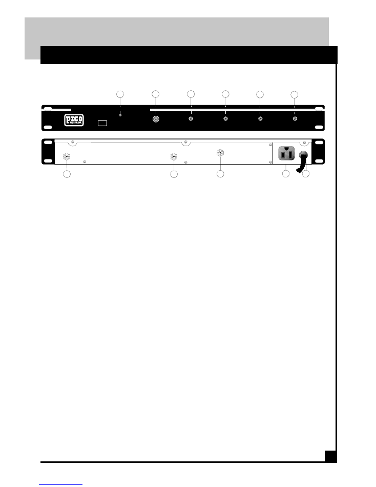
Front & Rear Panels
1.
Power On Indicator:
The LED indicates unit is operating.
2.
Test Point:
The -30 dB RF output test point is used to set the
RF output level and monitor channel
performance.
3.
RF Output Level:
This rugged PC Board mounted control sets the
RF output level.
4.
Audio Modulation:
The heavy duty PC mounted control is used to
set the audio modulation level.
5.
Aural Level:
This potentiometer controls the level of the
audio RF carrier.
6.
Video Modulation Adjust:
The PC Board mounted control is used to set
the video modulation level.
7.
Video In:
The PC Board mounted "F" connector accepts
the negative sync video information from
a satellite receiver or VCR.
8.
Audio In:
The audio from the satellite receiver or
VCR is connected to this PC Board mounted
F connector.
9.
RF Out:
The modulated output signal is available
on this PC Board mounted "F" connector.
10.
Convenience Outlet:
Allows looping of power between units.
11.
Power Cord:
The three prong type power plug connects to
a 120 VAC, 60 Hz electrical output or if
220VAC, 60 Hz, a two prong flat blade type
is used.
The PCM55 modulator is a crystal controlled modu-
lator. The modulator's operating frequency is deter-
mined by the frequency of a high accuracy tempera-
ture compensated crystal. The video is applied
through a front panel controlled potentiometer to an
integrated circuit. The amount of video applied to
the IC determines the depth of modulation. A surge
protection circuit is connected to the video input to
protect the IC from high level inputs. The audio is
coupled through a front panel controlled potentio-
meter to a high impedance input transistor. This
buffer circuit isolates the IC from the input, and
eliminates the need for special impedance matching.
Additionally, input surge protection is provided.
PCM55
AUDIO VIDEO MODULATOR
TEST
POINT
R.F.
OUTPUT
AUDIO
MODULATION
AURAL
LEVEL
ADJUST
LEVEL
ADJUST
VIDEO
MODULATION
-30 dB
1
2
3
4
5
6
CH-
RF OUT
120VAC
60Hz 10W
AUDIO IN
VIDEO IN
600 VA MAX
+
+
+
+
+
+
+
9
8
7
10
11
PICO MACOM INC.
12500 Foothill Blvd. • Lakeview Terrace, CA 91342 • (818) 897-0028 • (800) 421-6511 • FAX (818) 834-7197
6
I N S T A L L A T I O N
5
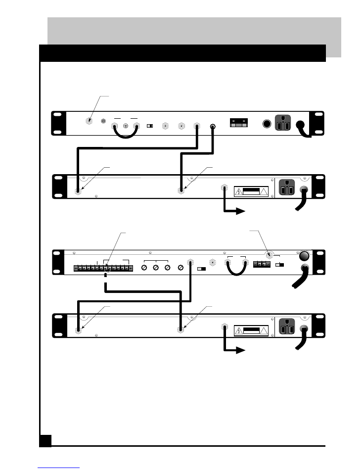
Satellite Receiver - 110 VAC Version
PCM55 MODULATOR
PR3200 SATELLITE RECEIVER
LNB
Power
IN
70 MHz
IF LOOP
OUT
INV NORM
FLAT
VIDEO OUT
COMP
VIDEO OUT
VIDEO
AUDIO
B/MAC
VIDCIP
H V
3/8 A 250V
120V
60 Hz 0.3A
IF GAIN
600 VA MAX
!
CAUTION
RISK OF ELECTRIC SHOCK
DO NOT OPEN
RF OUT
120VAC
60Hz 10W
AUDIO IN
VIDEO IN
600 VA MAX
'RF OUT' TO TV OR
DISTRIBUTION SYSTEM
+
+
+
+
+
+
VIDEO IN
AUDIO IN
FUSE
_
+
_
+
_
+
_
+
+
+
+
+
VIDEO
OUT
COMPOSITE
OUT
70 MHz
IN
OUT
AUDIO OUTPUT LEVEL
VIDEO
LEVEL
RF IN
950-1450
MHz
18V 250mA
LNB POWER
OUT
ON OFF
117V
.35A
60Hz
DATA
CLOCK
LANGUAGE
GND
+
_
MONO
LEFT
RIGHT
AUDIO OUTPUT
FUSE
AC25OV
1/2A
H
V
L
R
MONO
INV
NOR
AUDIO OUTPUT CONNECTION:
CENTER CONDUCTOR TO MONO+ (POS.)
SHIELD TO MONO- (NEG.)
PCM55 MODULATOR
!
CAUTION
RISK OF ELECTRIC SHOCK
DO NOT OPEN
RF OUT
120VAC
60Hz 10W
AUDIO IN
VIDEO IN
600 VA MAX
'RF OUT' TO TV OR
DISTRIBUTION SYSTEM
+
+
+
+
+
+
VIDEO IN
AUDIO IN
PR4200IRD SATELLITE RECEIVER
950-1750
MHz INPUT
FROM SATELLITE ANTENNA
950 - 1750 MHz
FROM SATELLITE ANTENNA
950 - 1750 MHz
PICO MACOM INC.
12500 Foothill Blvd. • Lakeview Terrace, CA 91342 • (818) 897-0028 • (800) 421-6511 • FAX (818) 834-7197
6
I N S T A L L A T I O N
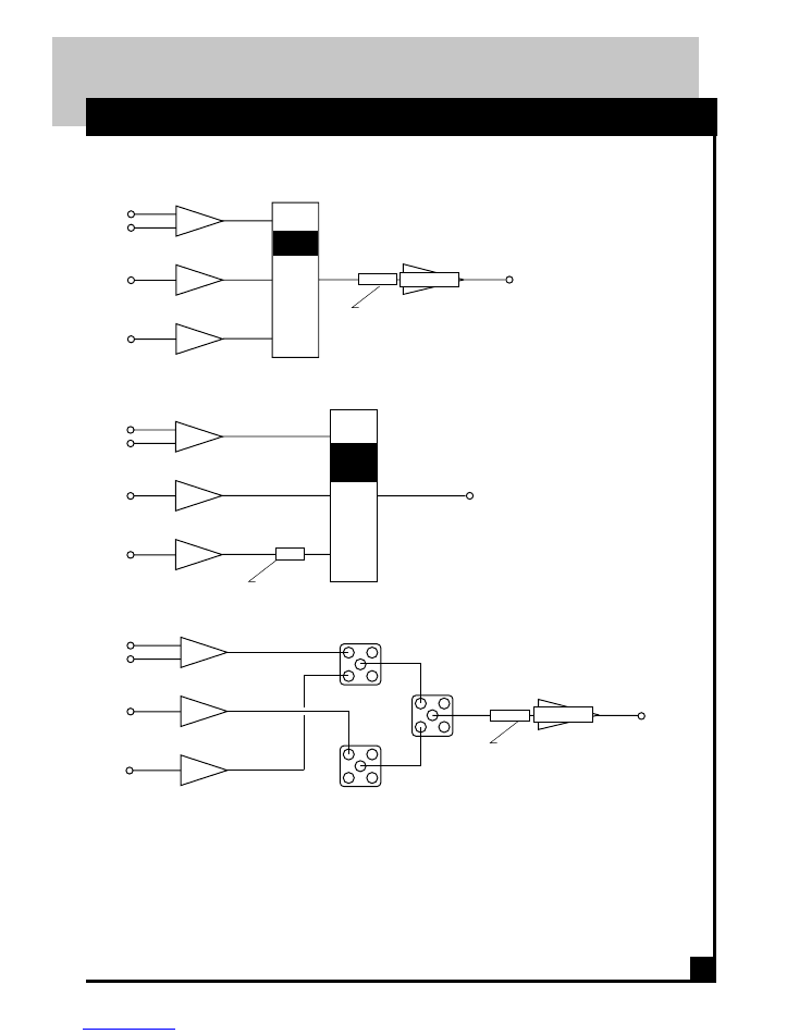
Signal Combining Methods
Ch. 2
Ch. 3
Ch. 4
+36dBmV
+60dBmV
PCM55
SP600
V
A
+52dBmV
+52dBmV
+52dBmV
+10dBmV
+14dBmV
+10dBmV
SP600
LBS/72L
V
A
+52dBmV
+52dBmV
+52dBmV
+10dBmV
+14dBmV
+10dBmV
PCM55
SP600
V
A
+50dBmV
+50dBmV
+50dBmV
+10dBmV
+14dBmV
+10dBmV
Ch. 2
Ch. 3
Ch. 4
PAD
+58dBmV
EVEN CHANNELS
Ch. 2
Ch. 3
Ch. 4
ODD CHANNELS
+43dBmV
+43dBmV
+36dBmV
+60dBmV
6dB PAD
6dB PAD
RF
IN
RF
IN
RF
IN
RF
IN
RF
IN
RF
IN
PCM55
PHC-12U
-16dB
CHC-16U
+10dB
to
+15dB
CA-30RK550
CA-30RK550
ATTENUATOR PAD
ATTENUATOR PAD
ATTENUATOR PAD
LBS/72L
LBS/72L
channels in another splitter and the two splitters are combined to a single
output with a third splitter. Each rack is then combined with a final splitter
prior to the CA-30RK550 post amplifier.
Note: (*) denotes either LBS, MBS, HBS or FMS strip amplifiers.
T
he output levels of the modulator should be
the same as the output of the off-air strip ampli-
fiers. The PCM55 modulators are usually com-
bined with either the SP600, LBS/HBS or 72
series strip amplifiers. Three methods are sug-
gested to combine strip amplifier,
modulator and processor outputs.
T
he PHC-12U twelve channel passive com-
biner consists of two rows of directional cou-
plers combined by a hybrid splitter. The direc-
tional coupler combining provides high isola-
tion (40 dB) between the inputs. Normally the
odd channels are combined on one row while
even channels are combined on the other row of
directional couplers. The combiner loss is 16
dB per channel.
T
he CHC-16U sixteen channel active com-
biner provides both signal combining and post
amplification of the headend signals. The unit
is basically a passive combiner and a CA30 all
in one package. Up to 16 signals may be
combined using the CHC-16U. The combiner
gain is 15 dB per channel.
T
he final method of combining signals uses
three hybrid splitters per headend rack. The odd
channels are combined in one splitter, the even-
Method 1
Method 2
Method 3

PICO MACOM INC.
12500 Foothill Blvd. • Lakeview Terrace, CA 91342 • (818) 897-0028 • (800) 421-6511 • FAX (818) 834-7197
A L I G N M E N T
FCC
NORMAL
INVERTED
OFFSET
CHANNEL
PICTURE
CRYSTAL
CRYSTAL
Harmonic.
kHz
NUMBER
CARRIER
Freq MHz
Freq MHz
Number
2
...................... 55.25 .................... 27.625
29.875
2
3
...................... 61.25 .................... 30.625
32.875
2
4
...................... 67.25 .................... 33.625
35.875
2
5
...................... 77.25 .................... 38.625
40.875
2
6
...................... 83.25 .................... 41.625
43.875
2
+25
A-1 .............. 115.275 .................. 28.81875
29.94375
4
+25
A-2 .............. 109.275 .................. 27.31875
28.44375
4
7
.................... 175.25 .................... 35.050
35.950
5
8
.................... 181.25 .................... 36.250
37.150
5
9
.................... 187.25 .................... 37.450
38.350
5
10
.................... 193.25 .................... 38.650
39.550
5
11
.................... 199.25 .................... 39.850
40.750
5
12
.................... 205.25 .................... 41.050
41.950
5
13
.................... 211.25 .................... 42.250
43.150
5
+12.5
A
14 ................ 121.2625 ................ 30.315625
31.440625
4
+12.5
B
15 ................ 127.2625 ................ 31.815625
32.940625
4
+12.5
C
16 ................ 133.2625 ................ 33.315625
34.440625
4
D
17 ................ 139.25 .................... 34.8125
35.9375
4
E
18 ................ 145.25 .................... 36.3125
37.4375
4
F
19 ................ 151.25 .................... 37.8125
38.9375
4
G
20 ................ 157.25 .................... 39.3125
40.4375
4
H
21 ................ 163.25 .................... 40.8125
41.9375
4
I
22 ................ 169.25 .................... 42.3125
43.4375
4
J
23 ................ 217.25 .................... 36.2083
36.958333
6
+12.5
K
24 ................ 223.2625 ................ 37.210375
37.960417
6
+12.5
L
25 ................ 229.2625 ................ 38.210375
38.960417
6
+12.5
M
26 ............... 235.2625 ................ 39.210375
39.960417
6
+12.5
N
27 ................ 241.2625 ................ 40.210375
40.960417
6
+12.5
O
28 ................ 247.2625 ................ 41.210375
41.960417
6
+12.5
P
29 ................ 253.2625 ................ 42.210375
42.960417
6
+12.5
Q
30 ............... 259.2625 ................ 43.210375
43.960417
6
+12.5
R
31 ................ 265.2625 ................ 44.210375
44.960417
6
+12.5
S
32 ................ 271.2625 ................ 45.210375
45.960417
6
+12.5
T33 ................ 277.2625 ................ 46.210375
46.960417
6
+12.5
U
34 ................ 283.2625 ................ 47.210375
47.960417
6
+12.5
V
35 ................ 289.2625 ................ 48.210375
48.960417
6
+12.5
W
36 ............... 295.2625 ................ 49.210375
49.960417
6
Channel Crystal Frequency
7
PICO MACOM INC.
12500 Foothill Blvd. • Lakeview Terrace, CA 91342 • (818) 897-0028 • (800) 421-6511 • FAX (818) 834-7197
9
8
Five Year Limited Warranty*
W A R R A N T Y
P
ico Macom, Inc.
warrants to the
original purchaser
this product shall be
free of defects in
material
and
craftsmanship with only the
limitations or exclusions set out
below.
During the warranty period Pico
Macom Inc. or an authorized Pico
Macom service facility will provide
free of charge, the parts and labor
necessary to correct defects in
material and workmanship.
WARRANTY DURATION
This warranty shall terminate five
years* from the original date of
purchase of the product or at a time
the product is:
1.
Misused or damaged due to
neglect or improper installation
2.
Modified
3.
Repaired by someone other
than the warrantor
4.
Sold by the original purchaser
STATEMENT OF
REMEDY
To obtain warranty service,
contact the salesperson where the
product was obtained. You will be
issued a Return Authorization (RA)
number which will be used to track
your product.
Be prepared to provide:
1.
The model number and channel
number of the product
2.
The date of purchase
3.
A specific identification of the
problem
Deliver the products to Pico Macom
Inc. or ship the products in the original
packing material at the address at the
bottom of the page. Include
satisfactory evidence of the date of
purchase.
Products will not be accepted by
Pico Macom Inc. without the RA
number clearly indicated on the
shipping label.
The foregoing constitutes the Pico
Macom, Inc. entire obligation with
respect to this product and the original
purchaser and any user or owner shall
have no other remedy and no claim for
incidental or consequential damages.
Some states do not allow limitations
on how long an implied warranty lasts
or do not allow the exclusions or
limitation
of
incidental
or
consequential damages, so the above
limitation and exclusion may or may
not apply to you.
This warranty gives you specific
legal rights, and you also have rights
which vary from state to state.

PICO MACOM INC.
12500 Foothill Blvd. • Lakeview Terrace, CA 91342 • (818) 897-0028 • (800) 421-6511 • FAX (818) 834-7197
10
9
N O T E S

PICO MACOM INC.
12500 Foothill Blvd. • Lakeview Terrace, CA 91342 • (818) 897-0028 • (800) 421-6511 • FAX (818) 834-7197
N O T E S

PICO MACOM INC.
12500 Foothill Blvd. • Lakeview Terrace, CA 91342 • (818) 897-0028 • (800) 421-6511 • FAX (818) 834-7197
10