Full Text Searchable PDF User Manual
© Panasonic Corporation, 2013.
All rights reserved. Unauthorized copying and distri-
bution is a violation of law.
Order Number SD1309Y36CE
E6
Rechargeable Shaver
Model No.
ES-LV95
Model No.
ES-LV65
North America
Latin America
TABLE OF CONTENTS
PAGE
PAGE
1 Warning
--------------------------------------------------------------
2
2 Specifications
-----------------------------------------------------
2
3 Troubleshooting Guide
-----------------------------------------
3
4 Disassembly and Assembly Instructions
----------------
8
5 Schematic Diagram
---------------------------------------------
13
6 Exploded View and Replacement Parts List
-----------
14

2
1 Warning
Caution:
• Pb free solder has a higher melting point that standard solder; Typically the melting point is 50 - 70
°
F (30 - 40
°
C) higher. Please
use a soldering iron with temperature control and adjust it to 750 ± 20
°
F (400 ± 10
°
C). In case of using high temperature solder-
ing iron, please be careful not to heat too long.
• Pb free solder will tend to splash when heated too high (about 1100
°
F / 600
°
C).
2 Specifications
3
3 Troubleshooting Guide
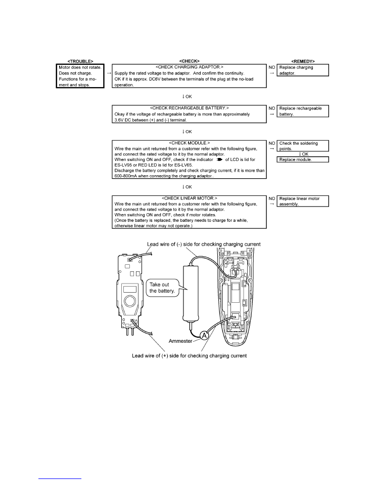
3.1.
Main unit and charging adaptor
NOTE:
Once taking the battery out, the shaver is RESET. The shaver must be charged for several seconds first.
NOTE:
Completely discharge and then fully charge before returning the shaver to the customer.
4
5
6
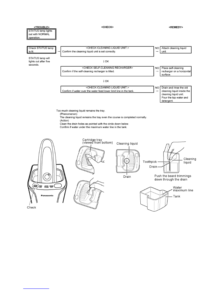
3.2.
Self-cleaning recharger (ES-LV95 only)
7
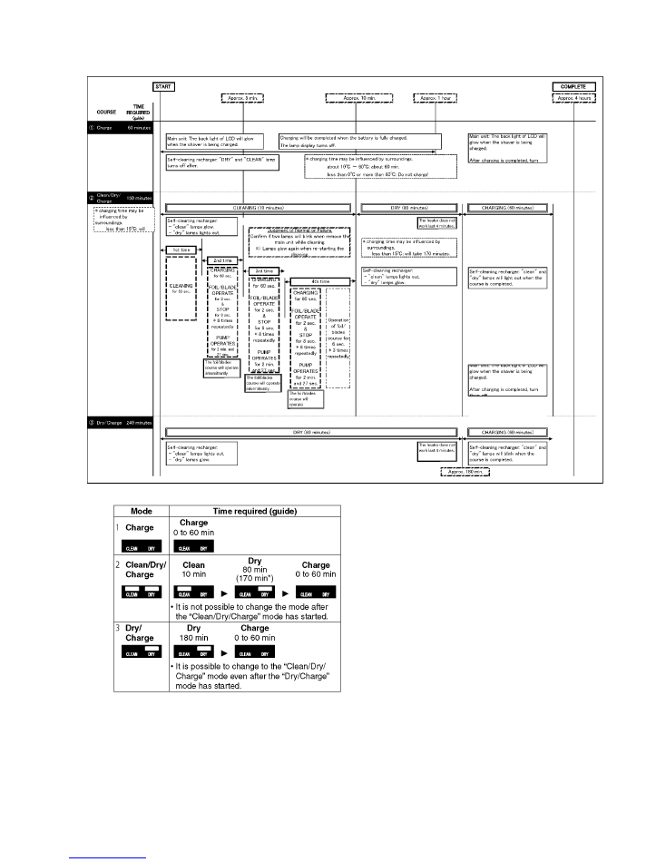
3.3.
Operation of self-cleaning recharger (ES-LV95 only)
8
4 Disassembly and Assembly Instructions
4.1.
Disassembly instructions
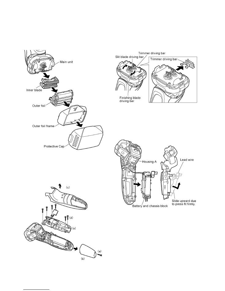
Follow the procedure below to disassemble the main unit.
1. Remove the cap, the outer foil with outer foil frame and
the inner blades.
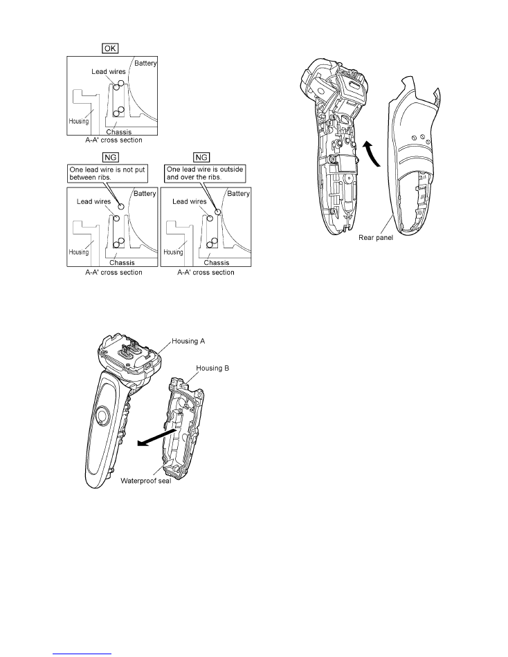
2. How to disassemble the housing A and B.
a) Loosen a screw.
b) Remove the bottom cover.
c) Remove the rear panel.
d) Loosen 6 screws.
e) Remove the housing B.
3. To remove the trimmer driving bar, finishing blade driving
bar or the slit blade driving bar, press bars outward.
4. Pull up the battery and chassis block from the linear
motor side first. Then, slide it upward and take it out from
the housing A.
NOTE:
Do not pull the battery and chassis block forcefully
due to connecting the linear motor by the lead wires.
9
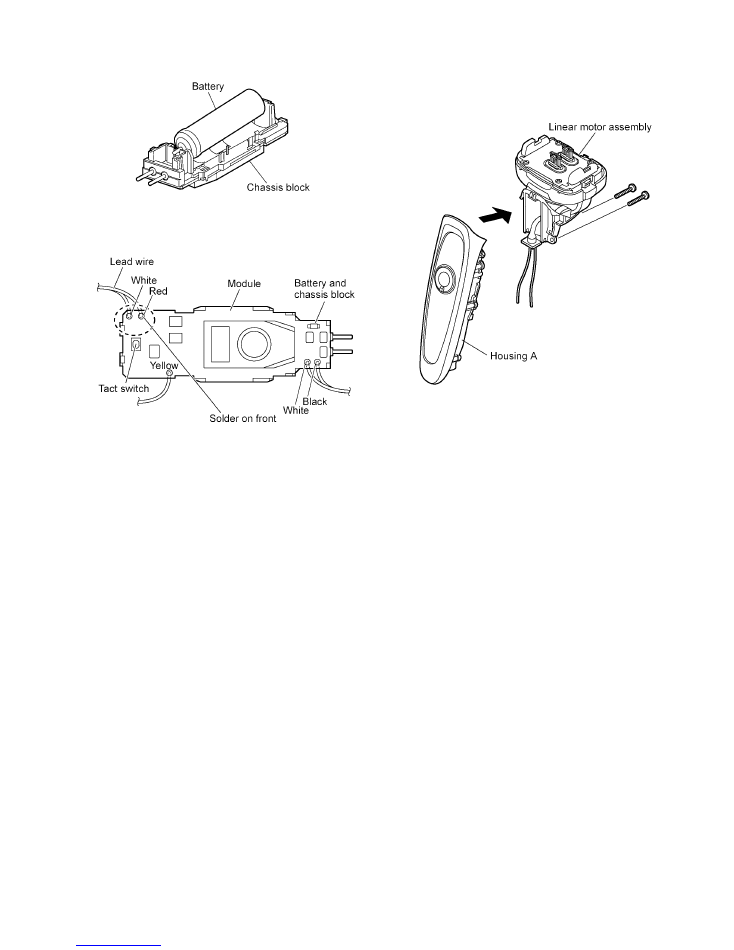
5. Take out the battery from the chassis.
6. Unsolder the lead wires from the module.
7. Loosen two screws.
8. Move gently the linear motor assembly down and unhook
it and remove the float springs from housing A.
10
4.2.
Caution in assembly
NOTE:
When reassembling, replace the new waterproof seal.
Make sure whether there is NO foreign substance sticking
around a part covered with waterproof seal.
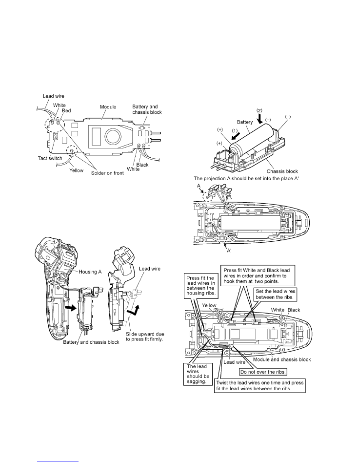
1. Solder the lead wires with the module.
NOTE:
Make sure of the color of lead wires.
2. Attach the tube holder. Tighten two screws between the
linear motor assembly and the housing A.
3. When inserting the module and chassis block into the
housing A, confirm if the module does not get any dam-
age or deformation.
4. Make sure that the lead wires set in position to avoid
abnormal noise. Install (+) terminal of battery into the ter-
minal plate at the bottom cover side and firmly set the bat-
tery sliding the direction of arrow. Attach (-) terminal of
battery.
NOTE:
Once taking the battery out, the shaver is RESET.
The shaver must be charged for about 10 seconds
first.
NOTE:
Completely discharge and then fully charge before
returning the shaver to the customer.
11
5. When putting the housing A and the housing B together,
make sure if the waterproof seal must be fitted properly
and no foreign substance sticking around.
6. Tighten six screws and attach the rear panel firmly.

12
7. Attach the bottom cover and tighten a screw.
8. Set the trimmer driving bar, the finishing blade driving bar
and the slit blade driving bar.
13
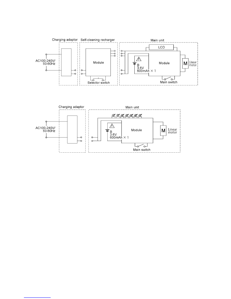
5 Schematic Diagram
5.1.
ES-LV95
5.2.
ES-LV65

14
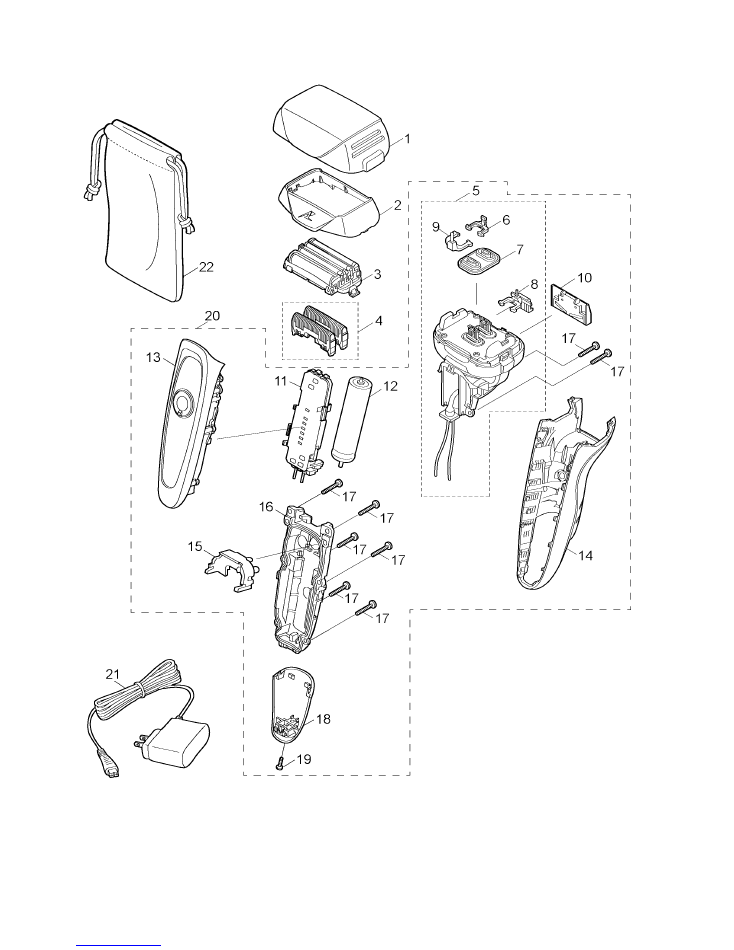
6 Exploded View and Replacement Parts List
6.1.
Exploded View for ES-LV95

15
6.2.
Replacement Parts List for ES-LV95
Safety
Ref. No.
Part No.
Part Name & Description
Quantity
Remarks
1
WESLV94X7158
PROTECTIVE CAP
1
2
WESELV9S0047
FOIL FRAME
1
3
WES9173P
SYSTEM OUTER FOIL
1
4
WES9170P
INNER BLADE
1ST
5
WESELV9L1007
LINEAR MOTOR ASSEMBLY
1
6
WESLV90L1077
SLIT BLADE DRIVING BAR
1
7
WESLV90L0327
WATERPROOF RUBBER
1
8
WESLV90L1087
TRIMMER DRIVING BAR
1
9
WESLV90L1177
FINISHING BLADE DRIVING BAR
1
10
WESELV9L1507
TRIMMER
1
11
WESLV95L2128
MODULE
1
12
WESLV95L2508
RECHARGEABLE BATTERY
1
LM-ION TYPE
13
WESLV95S3058
HOUSING A
1
14
WESELV9K3367
REAR PANEL
1
15
WES8258L0497
TERMINAL BASE
1
16
WES8238H0527
TERMINAL COVER
1
17
WESLV90H3068
HOUSING B
1
18
WES8176L6007
P TIGHT SCREW
8
M2-12
19
WESLA92L0487
CONNECTING PLATE
1
20
WESLV95K3120
BOTTOM COVER
1
21
WES8176L6057
TAPPING SCREW
1
M2-8
22
WESLV95S3030
BODY BLOCK
1
23
WESLV81K7P58
AC ADAPTOR
1
A-2 PLUG
24
WESLV95K4219
SELF-CLEANING RECHARGER
1
25
WESLV92K7358
CLEANING LIQUID UNIT
1
26
WES4L03-851
DETERGENT
1
(3PCS/BOX)
27
WESLV92K7367
CLEANING LIQUID FILTER
1
28
WESLA92K3747
SOFT CASE
1
-
WESLV95S8001
INDIVIDUAL BOX
1
only for U.S.A.
-
WESLV95S8002
INDIVIDUAL BOX
1
-
WESLV95S8100
OPERATING INSTRUCTIONS
1
16
6.3.
Exploded View for ES-LV65
17
6.4.
Replacement Parts List for ES-LV65
Safety
Ref. No.
Part No.
Part Name & Description
Quantity
Remarks
1
WESLV94X7158
PROTECTIVE CAP
1
2
WESELV8S0047
FOIL FRAME
1
3
WES9173P
SYSTEM OUTER FOIL
1
4
WES9170P
INNER BLADE
1ST
5
WESELV9L1007
LINEAR MOTOR ASSEMBLY
1
6
WESLV90L1077
SLIT BLADE DRIVING BAR
1
7
WESLV90L0327
WATERPROOF RUBBER
1
8
WESLV90L1087
TRIMMER DRIVING BAR
1
9
WESLV90L1177
FINISHING BLADE DRIVING BAR
1
10
WESELV9L1507
TRIMMER
1
11
WESLV65L2128
MODULE
1
12
WESLV95L2508
RECHARGEABLE BATTERY
1
LM-ION TYPE
13
WESLV65S3058
HOUSING A
1
14
WESELV9K3367
REAR PANEL
1
15
WESLA54L0497
REAR COVER
1
16
WESLV90H3068
HOUSING B
1
17
WES8176L6007
P TIGHT SCREW
8
M2-12
18
WESLV65K3120
BOTTOM COVER
1
19
WES8176L6057
TAPPING SCREW
1
M2-8
20
WESLV65S3030
BODY BLOCK
1
21
WESLV81K7P58
AC ADAPTOR
1
A-2 PLUG
22
WESLA92K3747
SOFT CASE
1
-
WESLV65S8001
INDIVIDUAL BOX
1
-
WESLV65S8002
INDIVIDUAL BOX
1
only for Canada
-
WESLV65S8100
OPERATING INSTRUCTIONS
1