Full Text Searchable PDF User Manual
1
www.phywe.com, © All rights reserved
09057-99 / 2115
Operating Instructions
XR 4.0 expert unit, X-ray unit, 35
kV
09057-99
PHYWE Systeme GmbH & Co. KG
Robert-Bosch-Breite 10
37079 Göttingen
Germany
Tel
+49
(0)
551
604-0
Fax
+49
(0)
551
604-107
E-mail info@phywe.de
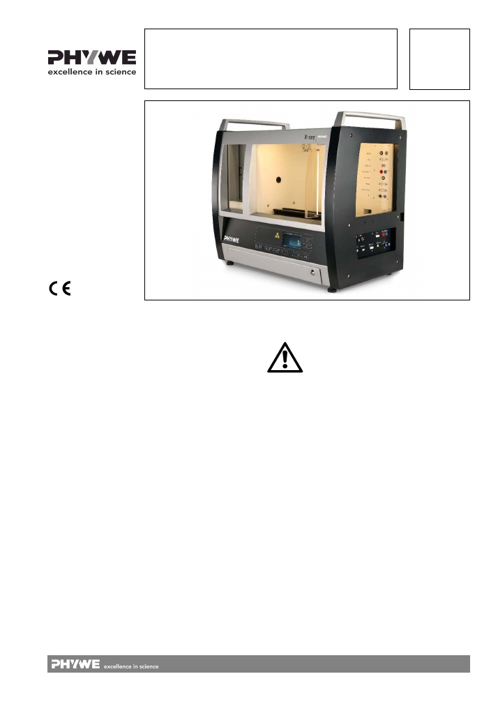
Fig. 1: 09057-99, XR 4.0 expert unit, X-ray unit, 35
kV
The unit complies
with the applicable
EC regulations.
1
SAFETY INSTRUCTIONS
2
OPERATING INSTRUCTIONS
3
INSTRUCTIONS OF THE GERMAN X-RAY
ORDINANCE
4
PURPOSE AND CHARACTERISTICS
5
FUNCTIONAL AND OPERATING ELEMENTS
6
OPERATION
7
CHECKLIST
8
TECHNICAL DATA
9
SCOPE OF SUPPLY
10
ACCESSORIES
11
WARRANTY
12
DISPOSAL
13
APPENDIX
1 SAFETY
INSTRUCTIONS
Read the operating instructions thoroughly and com-
pletely prior to starting the unit. This is important for your
own protection and for avoiding damage to the unit.
Use the unit solely for its intended purpose.
The unit is intended for use in dry and dust-free rooms
where there is no risk of explosion.
Prior to connecting the unit to the mains power supply,
ensure that the protective conductor of the power supply
unit is correctly connected to the protective conductor of
the mains power supply network. The mains power plug
may only be plugged into a mains power socket that is
equipped with a protective conductor. Do not eliminate
this protective effect by using an extension lead without a
protective conductor.
Ensure that the mains voltage that is stated on the type
plate of the unit matches the mains voltage of your power
supply network.
When setting the unit up, ensure that the mains power
switch and the device plug are freely accessible. Ensure
also that the venting slots of the unit are not covered or
blocked.
Do not connect any devices to the unit other than the
ones that are intended for this purpose.
Attention: Disconnect the unit from the power supply
prior to loosening, replacing, or removing any of the ca-
ble connections!
Ensure that no liquids or objects penetrate the unit
through the venting slots.
2
www.phywe.com, © All rights reserved
09057-99 / 2115
Do not start the unit if the mains power cable or the unit
itself are damaged.
Switch the unit off after using it. Continuous operation is
not permissible. The maximum runtime per day is
10 hours. It is not a syfety risk if you the tube for longer
intervals but this could reduce the lifetime of the tube.
Start the unit at least twice per year and check its safety
functions. The tests that are included in the checklist at
the end of this document must be performed.
If damaged, the unit must be returned to the manufac-
turer for repair. Only the manufacturer or a certified com-
pany that has been appointed by the manufacturer are
authorised to repair and maintain the unit.
Since X-ray units generate dangerous radiation that is
hazardous to health, only trained and qualified persons
are authorised to start the X-ray unit in accordance with
the local, country-specific rules and regulations.
In Germany: When working with the X-ray unit, the man-
datory measures and duties that are outlined in the Ger-
man X-ray ordinance (Röntgenverordnung, RÖV) must
be strictly complied with.
The requirements of the certificate are to be followed
In particular, the operator must ensure that
o
the X-ray unit is protected against access by unau-
thorised persons;
o
the unit is not in use longer than necessary;
o
persons working with the unit do not remain in the
direct vicinity of the unit longer than absolutely
necessary.
The use of the unit is prohibited if
o
the sliding door that is made of lead-containing
acrylic glass and that is used for opening the ex-
periment chamber, or the other protective glass
windows that are used to observe the X-ray unit
and the experiment chamber, are damaged;
o
the fan at the X-ray plug-in side inside the unit is
inoperative (acoustic check);
o
the safety circuits for interrupting the X-ray opera-
tion when the sliding door is opened do not oper-
ate properly.
How to clean:
o
Do not use diluter/thinner!
o
Clean with cloth and appropriate cleaning agent.
Transport
o
Do not stress the drawer during transport. The
device should stand only on its feet.
o
During transport make sure that the sliding
door is not locked with the lock bar. If so,
unlock the door using button IV, Fig 5 (switch
on the device to use the button). The door
should not be open either - fix it with the
S-LOCK.
2 OPERATING
INSTRUCTIONS
The device fulfils the technical requirements that are
summarised in the current guidelines of the European
Community. The characteristics of the product entitle it to
bear the CE mark.
The unit must be used under the supervision of an expert
and in the electromagnetically controlled environment at
research, teaching, and training facilities (schools, uni-
versities, institutes, and laboratories).
This means that, in such an environment, radio transmis-
sion devices, e.g. mobile phones, should not be used in
the direct vicinity of the unit. The connected cables must
not be longer than 2
m.
Electrostatic charges or similar electromagnetic phe-
nomena (HF, bursts, indirect lightning discharge, etc.)
may affect the unit so that it will not work within the
specified data range.
Occuring interfering signals may result in an automatic
shutdown of the high voltage during measurement! In
this case please follow section 6.6.
The following measures reduce or eliminate potential in-
terferences: avoid carpets; provide equipotential bond-
ing; perform the experiments on a conductive, earthed
surface; use shields and shielded cables. Do not use ra-
diofrequency transmitters (radio sets, mobile phones) in
the direct vicinity of the unit. After a total exit by actuating
the mains power switch, perform a reset.
This unit corresponds to class A of the standard DIN
EN 61326 and may be used without any restriction only in
non-residential areas. If - although the use of the unit is re-
stricted to special classrooms in a school or another training
facility - electromagnetic interf erences occur in the surround-
ing residential area, the operator can be required to take the
appropriate measures (e.g. shielding, long distance with re-
gard to sensitive equipment, short periods of use, use of the
shortest possible connecting cables, etc.) and to pay for
these measures.
3 INSTRUCTIONS OF THE GERMAN X-RAY
ORDINANCE
In Germany, the operation of the X-ray unit is subject to the
regulations that are outlined in the X-ray ordinance (Rönt-
genverordnung, RöV). In accordance with this ordinance, the
unit fulfils the mandatory requirements of an X-ray unit for
schools as well as those of a full-protection device.
In Germany, the operation of the unit is not subject to ap-
proval, but to reporting. Thus, report the unit to the appropri-
ate controlling institution.
For reporting, the test certificate and a copy of the design ap-
proval must be submitted to the responsible authorities. Only
specifically trained and instructed personnel is authorised to
operate the unit. When this unit is used as an x-ray device for
schools a radiation protection officer must be authorized.
If the unit operates at the maximum operating data, the local
dose rate at a distance of 0.1
m from the parts of the housing
that can be touched is less than 1
μ
Sv/h.
Two independent safety circuits monitor the opening of the
sliding door that leads to the experiment chamber.
X-rays can only be generated when the sliding door is prop-
erly locked. The safety circuits also prevent the maximum
permissible operating values of the tube from being ex-
ceeded.
Do not use the device if the X-ray unit is manipulated in a
way that is not necessary for its set-up or for performing ex-
periments. It is absolutely forbidden to loosen the safety
screws of the sheet steel housing or to tamper with the win-
dows. Only the manufacturer is authorised to repair the unit.
For any operation of the unit outside of Germany, the appli-
cable local rules and regulations must be complied with.

3
www.phywe.com, © All rights reserved
09057-99 / 2115
4 PURPOSE
AND
CHARACTERISTICS
4.1 Purpose of the unit
The X-ray unit is a demonstration unit as well as a unit for
laboratory courses. It has been specially developed to fulfil
the requirements of education at schools and universities. In
addition to its use in the education of physics, it can also be
used for education in the medical sector and the related
technical disciplines. A particularly noteworthy distinguishing
feature of this microprocessor-controlled compact unit is the
quick-change feature of the X-ray tubes that enables the per-
formance of experiments with different X-ray tubes and,
thereby, different anode materials.
The following X-ray tubes, which are integrated in special,
ready-to-use plug-in units, are available:
Plug-in unit with a Cu X-ray tube
order no. 09057-51
Plug-in unit with a Mo X-ray tube order no. 09057-61
Plug-in unit with a Fe X-ray tube
order no. 09057-71
Plug-in unit with a W X-ray tube
order no. 09057-81
Do not use other plug-ins (predecessors 09057-50 / -60 /
-70 / -80 are still compatible).
Apart from simple fluoroscopic experiments and experiments
on dosimetry, the integrated rate meter and the additional
goniometer enable spectroscopic experiments on atomic
physics and solid-state physics.
The operating and control parameters are set either directly
on the unit or with a computer via USB.
A colour TFT display in the control panel is used for the direct
control of the unit (and for displaying all of the operating and
control parameters as well as the measurement values). The
keys around the display in the control panel enable the com-
plete operation and control of the unit in its basic functions.
4.2 Overview of the possible experiments
The following experiments can be performed with the unit
and the corresponding additional components:
Radiography of objects and observation with the aid of a
fluoroscopic screen
Preparation of X-ray images of irradiated objects
Detection of the ionising effect of X-rays (dosimetry)
Detection of Bragg reflection
Characterisation of X-ray spectra
Determination of the characteristic X-ray lines of various
anode materials (Cu, Mo, Fe, and W), thereby verifying
Moseley’s law
Detection of the characteristic lines K
α
1
and K
α
2
in higher
order diffraction
Monochromatisation of X-rays with the aid of monocrys-
tals or metal foil
Crystal analysis with the aid of X-ray spectroscopy and
Laue and Debye-Scherrer methods
Determination of Planck’s quantum of action from the
short-wave limit of the bremsspectrum (Duane-Hunt law
of displacement)
Determination of the Rydberg constant
Determination of the absorption coefficients as a function
of the thickness and atomic number of the absorber ma-
terial and of the photon energy
Detection of absorption edges
Demonstration of the effects of contrast media in medical
applications
Compton
scattering
5 FUNCTIONAL AND OPERATING ELEMENTS
5.1 XR 4.0 X-ray expert unit
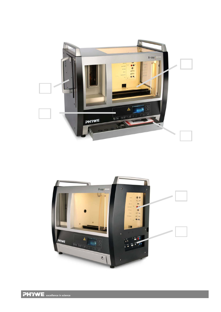
The XR 4.0 X-ray expert unit includes the following main
components (see Fig. 2 and Fig. 3).
5.1.1 Experiment chamber
For performing experiments and for holding additional
equipment, such as a goniometer or other experiment mate-
rial.
5.1.2 Control panel
For setting the operating values and control quantities as well
as for displaying all of the available measurement values.
5.1.3 Tray for accessories
For storing additional components.
5.1.4 Tube plug-in unit with a plug-in bay
Module in which the X-rays are generated.
5.1.5 Socket panel in the experiment chamber
For connecting various components, either for the connection
to the XR 4.0 X-ray expert unit or for the connection to other
peripheral equipment via the socket panel on the outside on
the right-hand side of the unit.
5.1.6 External Socket panel
The external socket panel on the right-hand side of the unit is
the counterpart of the socket panel inside the experiment
chamber.
4
www.phywe.com, © All rights reserved
09057-99 / 2115
Fig. 2: Front view of the XR 4.0 X-ray expert unit (09057-99) including X-ray tube
Fig. 3: View from the right side
XR 4.0 X-ray expert unit (09057-99)
1
4
2
3
5
6
5
www.phywe.com, © All rights reserved
09057-99 / 2115
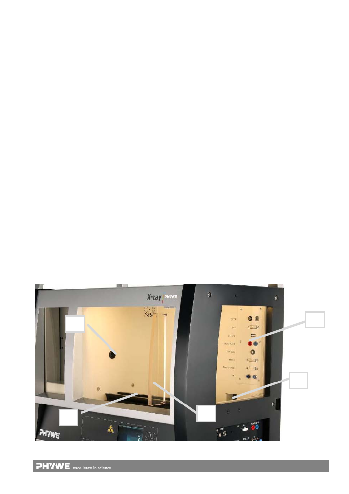
5.2 Experiment chamber (
1
)
The experiment chamber (Fig. 4) includes the following func-
tional elements:
5.2.1 Sliding door (A)
Made of lead-containing acrylic glass. The door is perma-
nently monitored by a safety circuit and it is either locked or
released via an actuator.
For monitoring the position of the sliding door (open/closed),
two independent encoders are connected to the central
safety unit of the XR 4.0 X-ray expert unit. If the sliding door
is closed and the unit is in a safe state, the operator can lock
the sliding door via the control panel. The position of the ac-
tuator for this purpose is monitored by two additional inde-
pendent encoders that are also connected to the central
safety unit.
In order to open the sliding door,push it first against the stop
on the right-hand side.The S-Lock is now unlocked and the
door can be opened.
X-rays can only be generated when the door is locked.
5.2.2 X-ray outlet (B)
The X-ray outlet is located on the left-hand side of the ex-
periment chamber. It is used to hold metal tubes with circular
double-apertures for generating a beam of rays that is suited
to the experiment in question.
5.2.3 Socket panel in the experiment chamber (C)
Socket panel for the connection of devices that are located
inside the experiment chamber, e.g. a goniometer. The sock-
ets connect the devices either with the X-ray unit itself or they
lead to the external socket panel that is located on the right-
hand side of the unit (looping-through). This enables, for ex-
ample, the control or read-out from the outside of a digital
camera that is located inside the experiment chamber.
5.2.4 Working channel (D)
The working channel is located on the back wall of the ex-
periment chamber, at the bottom on the right-hand side. It
ends on the right-hand side outside of the unit and, thereby,
forms a connection through which, for example, a contrast
medium can be fed into the experiment chamber through
hoses during the operation of the unit. The shape and cross-
section of the working channel ensure that no X-radiation can
escape.
5.2.5 Optical bench (E)
An optical bench is fastened to the bottom of the experiment
chamber along the optical axis of the X-rays. The adapters
that are required for the experiments can be attached to, and
shifted on, this optical bench.
5.2.6 Temperature monitoring system
The temperature of the air inside the experiment chamber is
monitored and controlled via a fan system.
5.2.7 Interior lighting
The linear LED lighting for illuminating the experiment cham-
ber can be activated as required.
5.2.8 Holder for the goniometer
The goniometer 09057-10 is magnetically secured inside the
experiment chamber via magnetic foil and has an electrical
connection to the XR 4.0 X-ray expert unit (plug & measure).
5.3 Control panel at the front of the unit (
2
)
The control panel at the front of the unit is shown in Fig. 5
and described in Table 1.
5.4 Tray for accessories (
3
)
The lower part of the XR 4.0 X-ray expert unit includes a tray
with moulds for the following components (for example):
Geiger-Müller counter tube
X-ray
energy
detector
Diaphragms
Fig. 4: experimentation chamber
C
D
B
E
A
6
www.phywe.com, © All rights reserved
09057-99 / 2115
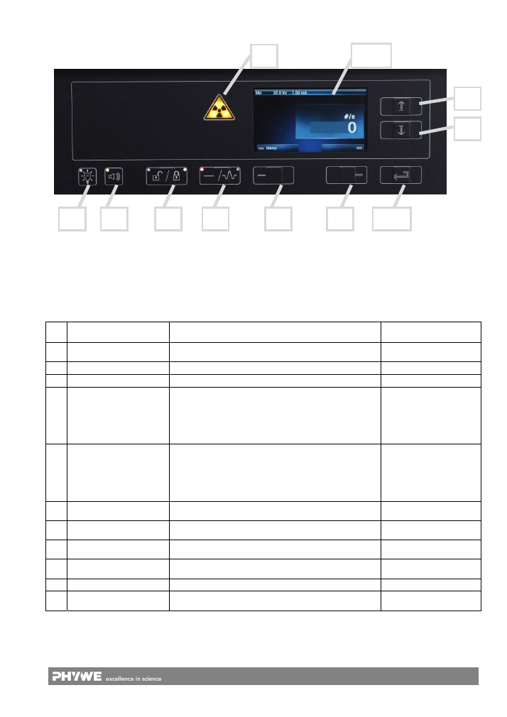
Table 1: Overview of the functional elements of the control panel
No. Name/Type
Function
Lighting colour:
function activated
I
Triangular warning symbol
“X-rays”
X-ray status indication
Bright yellow ( 2 LEDs)
II
Lighting (button)
For switching the light in the experiment chamber on/off
Green
III
Loudspeaker (button)
Acoustic indication of the pulses
Green
IV
Door status (button)
For locking and unlocking the door
White:
not
lockable
Left LED green:
door can be locked
right LED green:
door
locked
V
X-rays (button)
For activating the X-radiation
White: it is not possible
to swith on the unit
Left LED green:
X-ray can be activated
right LED green:
X-ray is activated
VI
Button (no name)
The selection of the menu function will be displayed on the
screen above (on the bottom on the left-hand side)
White
VII
Button (no name)
The selection of the menu function will be displayed on the
screen above (on the bottom on the right-hand side)
White
VIII Arrow key “up” (button)
For setting experiment parameters and for scrolling through
the menu
White
IX
Arrow key “down” (button)
For setting experiment parameters and for scrolling through
the menu
White
X
Enter (button)
For confirming the selected value
White
XI TFT
display
For displaying the menus for the manual control of the unit
(77
mm x 50
mm)
Polychrome
Fig. 5: Control panel at the front of the unit
VIII
IX
I
XI
II
III
IV
V
VI
VII
X
7
www.phywe.com, © All rights reserved
09057-99 / 2115
5.5 X-ray plug-in unit (
4
)
Plug-in unit for holding the adjusted X-ray tube in a sheet
steel housing with a carrying handle, ready for use in the
X-ray XR 4.0 X-ray expert unit. The housing of the tube has a
catch lock and two safety contact pins that enable the tube
operation only if the plug-in unit has been installed correctly.
Fig. 6: X-ray plug-in unit on the left-hand side of the unit
The bay for receiving the X-ray plug-in unit is equipped with
coupling sockets and subsequent safety switches. These are
connected to the central safety monitoring system of the
XR 4.0 X-ray expert unit.
The following ready-prepared plug-in units are available:
Plug-in unit with a Cu X-ray tube
order no. 09057-51
Plug-in unit with a Mo X-ray tube order no. 09057-61
Plug-in unit with a Fe X-ray tube
order no. 09057-71
Plug-in unit with a W X-ray tube
order no. 09057-81
The plug-in units consist of a sheet steel housing with a fac-
tory-adjusted X-ray tube. In order to prevent them from over-
heating, the tubes are enclosed in a Duran glass cylinder.
This glass cylinder has side connecting pieces through which
forced air cooling via a fan in the XR 4.0 X-ray expert unit is
ensured.
The plug-in units also have an HV plug and a plug for the
tube cathode heating so that the operating values can be
taken over from the corresponding sockets of the XR 4.0
X-ray expert unit.
Make sure that the plug-in is inserted completely. Otherwise,
it is not going to work.
Handle the plug-ins with care!
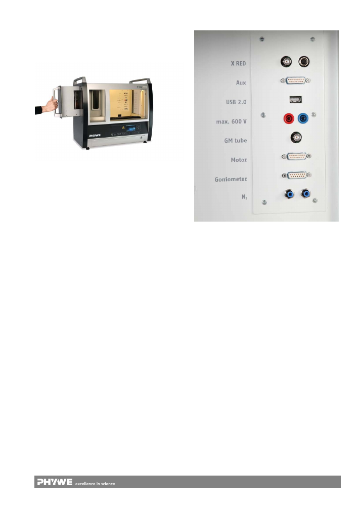
5.6 Socket panel inside the experiment chamber (
5
)
Fig. 7: Socket panel inside the experiment chamber
The socket panel at the back wall of the experiment chamber
(Fig. 7) includes the following sockets for the connection of
components in the experiment chamber. The names that are
stated inside the unit are printed in italics.
From the top down:
X RED:
For connecting the X-ray energy detector
09058-30 to the multi-channel analyser 13727-99; BNC
signal cable, supply cable (direct connection to the ex-
ternal socket panel on the right-hand side of the unit).
Aux:
Multi-pole socket for connecting various devices in
the experiment chamber (direct connection to the exter-
nal socket panel on the right-hand side of the unit).
USB 2.0:
Socket for connecting digital cameras etc. (di-
rect connection to the external socket panel on the right-
hand side of the unit).
Max 600
V
: 2
mm x 4
mm sockets, e.g. for charging the
capacitor plates (order no. 09057-05) for dosimetry ex-
periments (direct connection to the external socket panel
on the right-hand side of the unit).
GM tube:
BNC socket for connecting the Geiger-Müller
counter tube, type B 09005-00.
Motor:
Socket for connecting the rotating stage XRstage
09057-42 of the computed tomography set XRCT 4.0
X-ray 09180-88.
Goniometer:
Connecting socket for the goniometer
09057-10.
N
2
:
For feeding in protective gas or for the connection to
a vacuum pump (direct connection to the external socket
panel on the right-hand side of the unit).
8
www.phywe.com, © All rights reserved
09057-99 / 2115
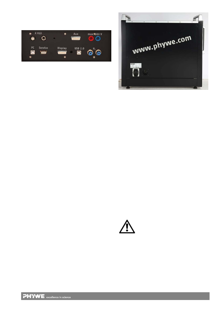
5.7 External socket panel on the right-hand side (
6
)
The external socket panel (Fig 8) on the right-hand side of
the unit is the counterpart of the socket panel inside the ex-
periment chamber.
Fig. 8: External socket panel on the right-hand side of the unit
Here, the following components can be connected. The
names that are stated on the unit are printed in italics.
Lower line of the socket panel:
PC:
For the connection to the control PC via the “meas-
ure” USB 2.0 port.
Service
: For the connection of a specially configured PC
for updating the device settings and for diagnosis pur-
poses (for authorised specialist personnel only).
Display:
For the connection of a “Display Connect” RF
adapter (09057-19). It is used to display measurement
values and device parameters on the large-scale display
unit (07157-93).
USB 2.0:
Socket for connecting digital cameras etc. (di-
rect connection to the socket panel inside the experiment
chamber).
N
2
:
For feeding in protective gas or for the connection to
a vacuum pump (direct connection to the socket panel
inside the experiment chamber).
Upper line of the socket panel:
X RED:
For connecting the X-ray energy detector 09058-
30 to the multi-channel analyser 13727-99; BNC signal
cable, supply cable (direct connection to the socket panel
inside the experiment chamber).
Aux:
Multi-pole socket for connecting various devices in
the experiment chamber (direct connection to the socket
panel inside the experiment chamber).
Max 600 V
: 2 x 4-mm-sockets, e.g. for charging the ca-
pacitor plates (order no. 09057-05) for dosimetry experi-
ments (direct connection to the socket panel inside the
experiment chamber).
6 OPERATION
This section describes the start-up of the unit and provides
an overview of its operation. Please read this section care-
fully in order to avoid problems or malfunctions.
6.1 Transport
Do not stress the drawer during transport. The device
should stand only on its feet.
During transport make sure that the sliding door is not
locked with the lock bar. If so, unlock the door using but-
ton IV, Fig 5 (switch on the device to use the button). The
door should not be open either - fix it with the S-LOCK.
6.2 Start-up
Connect the unit to the power supply via the supplied power
cable with an IEC connector. The socket for this purpose is
located at the back of the unit (see Fig. 9).
Fig. 9: Back of the unit with the socket for the power cable
and the central ON/OFF switch
6.3 Starting the unit
The central ON/OFF switch of the unit is located at the back
of the unit (Fig. 9). Actuate this switch to switch the unit on.
After the start, the unit will perform an automatic self-test
(safety test). For this purpose, the operator must open the
sliding door completely one time and then close it again. The
device status that is thus determined will be indicated on the
display unit in the control panel via the colours of the but-
tons IV and V.
In order to open the sliding door, push it first against the stop
on the right-hand side.The S-Lock is now unlocked and the
door can be opened.
If the unit had been switched off with the door being locked,
the door will be automatically unlocked once the unit is
switched on. The operator must then open the radiation pro-
tection door once and close it again (check of the safety cir-
cuit; described in the operating instructions and on the dis-
play unit).
If the X-ray plug-in is completely inserted and the door is
closed with the use of the SLOCK the left LED of button IV is
glowing in green. All other LEDs are enlighted in white. Now,
the unit is ready for use.
If this is not the case, contact the Service of PHYWE for help.
Caution:
It is only possible to lock the sliding door, if the
plug in with the X-ray tube is completely inserted
into the device.
if you switch off the device while it is locked you
have to switch it on again to unlock the door.
When used for the first time, the X-ray tubes should not run
at full power. Instead, we recommend letting the tubes run for
approximately 10 minutes at the maximum beam current, but
with an acceleration voltage that is limited to 25
kV maximum.
This procedure must also be repeated if a tube has not been
used for several weeks.
9
www.phywe.com, © All rights reserved
09057-99 / 2115
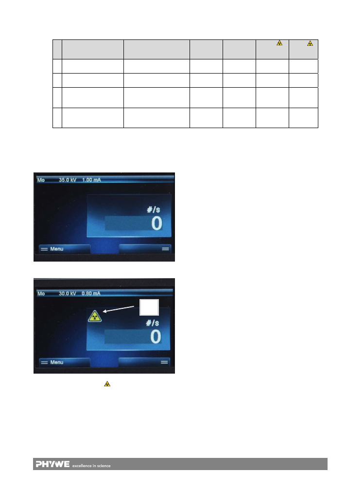
The unit has four device statuses that are listed in Table 2.
Depending on the status, the unit can be controlled entirely
via the buttons on the control panel together with the graphi-
cal representation.
Fig. 10: Screen for controlling the unit at the front of the unit.
The x-radiation is not activated.
Fig. 11: Screen for controlling the unit at the front of the unit.
The x-radiation is active. Sign
appears on the screen.
The change of the representation and the control of the unit
via the menu are performed via the buttons VI-X (Fig. 5).
As soon as the x-radiation is activated a yellow symbol ap-
pears on the screen (See Fig. 11).
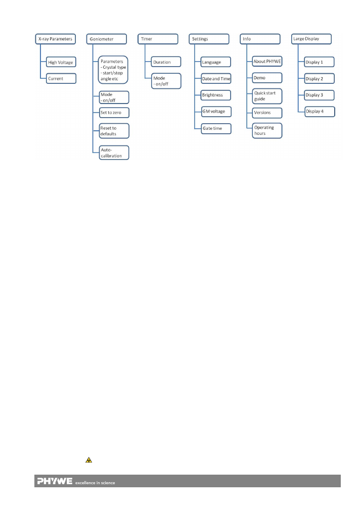
6.4 Menu
structure
On the main level, the menu structure of the unit includes the
following items:
1. X-ray
parameters
2. Goniometer
3. Timer
4. Settings
5. Info
6. Large
Display
The buttons VI-X on the control panel are used to navigate
through the menu, to change the settings, and to quit the
menu.
6.4.1 X-ray parameters
This menu is used to set the high voltage and the beam cur-
rent. By selecting the submenus for the high voltage or beam
current and by pressing the dynamic buttons on the right of
the display unit, the high voltage of the tube can be set to a
value between 0.0 kV and 35.0 kV and the emission current
to a value between 0.00 mA and 1.00 mA.
6.4.2 Goniometer
Menu and parameterisation of the goniometer (09057-10).
The operation of the goniometer in the X-ray unit is described
in the operating instructions for 09057-10.
6.4.3 Rotation stage
Menu and parameterisation of the rotation stage XRstage
(09057-42). The operation of the rotation stage inside of the
X-ray unit is described un the operating instructions for
09057-42.
6.4.4 Timer
This menu is used to define the start and stop conditions for
the experiments (X-radiation ON/OFF).
6.4.5 Settings
This menu is used to define certain fundamental settings.
6.4.6 Info
Menu for status information concerning the unit.
6.4.7 Large Display
If a sender (09057-09) is connected to the XR 4.0 expert unit
and transfers date to a large display in this part of the menu
the parameter for the display can be set.
Table 2: Overview concerning the three possible operating states
Status/X-radiation
Description
Button IV
Button V
Sign
panel
(Fig. 5, I)
Sign
Display
(Fig. 11)
1 Cannot be switched on
The sliding door is not
closed and not locked.
white white
off off
2 Cannot be switched on
The sliding door is closed
but not locked
Left LED
green
white off
off
3 Can be switched on
The unit is in a safe state
and the X-radiation can
be activated.
Right LED
green
Left LED
green
on off
4 On
The unit is in a safe state
and the X-radiation is ac-
tive.
Right LED
green
Right LED
green
on on
Y
10
www.phywe.com, © All rights reserved
09057-99 / 2115
Fig. 12: Menu structure of the unit - overview
6.5 Control via a PC with “measure”
As an alternative with regard to the direct control of the unit
via the control panel, the control of the unit and the represen-
tation of the measurement values can also be realised with
the aid of a PC and the “measure” software (14414-61).
6.6 Automatic shutdown of high voltage in case of fail-
ure
In case of interfering signals in the mains supply, the high
voltage will automatically be cut off in means to protect the
device from defects (introduced with firmware V
2.1). This
can be discerned by the fact that the x-ray tube stops to
gleam.
Running measurements eventually will not stop during the
shutdown, so they probably have to be restarted.
After removing the source of interference, check the door
status button IV and lock the door, if necessary (LED has to
be green). Afterwards, the device can be put into operation
again by pressing the X-ray button V. Thus, the high voltage
is switched on again and the measurement can be repeated.
If the device is controlled via a PC, the USB connection has
to be unplugged and plugged in, anew.
7 CHECKLIST
According to this list the device should be checked at least
two times per year:
1. Check if the device shows any damage.
2. All glass panes must be undamaged.
3. Start the x-ray device according to chapter 6.1, 6.2 of this
operating instruction. Perform a functional test of the
status indications, e.g.:
Do all LEDs work porperly?
Is symbol „I“ enlighted in operating state 3 (Ta-
ble 3)?
4. Check all functionalities according to table 2 of this oper-
ating instruction:
In operating state 1 and 2 it is not possible to acti-
vate the x-radiation.
In operating state 3 the x-radiation is not active, the
door is locked.
Only in operating state 4 the x-radiation is active.
Does sign
appear on the screen (Fig. 11)?
If you activate the x-radiation with the following pa-
rameters: anode current 1
mA, anode voltage
35
kV, the x-ray tube should gleam brightly.
The device is only ready for use if the tests are performed in
the right way and successfully. Even if
only one
test fails the
device must not be used. Please contact the Phywe service
in this case. (service@phywe.com).
8 TECHNICAL
DATA
Operating temperature range: 5-40
°C, typically 25
°C
Rel. humidity < 70
%
Microprocessor-controlled XR 4.0 X-ray expert unit with a
central safety monitoring system and two independent
monitoring circuits for the door position and two inde-
pendent monitoring circuits for the actuator of the door
locking system
4 X-ray tubes that are visible during the operation (Fe,
Cu, Mo, and W)
Lead enforced acrylic class windows, safe according to
DIN EN 61010
Integrated display unit for displaying measurement val-
ues and device parameters
“Display Connect” interface for the connection of a large-
scale display unit
Experiment chamber accessible during the operation via
a working channel
Integrated LED line for interior lighting (can be activated
as required)
Internal and external socket panel for easy cabling
Loudspeaker for the acoustic indication of measurements
with the Geiger-Müller counter tube
N
2
:
max 5 bar
Lockable tray for storing accessories
High voltage: 5.0-35.0
kV
Emission current: 0.0-1.0
mA
counter tube voltage: 100-600
V
Counting
time:
0.5-100
s
Exposure time: 0-100 minutes
11
www.phywe.com, © All rights reserved
09057-99 / 2115
With an additional goniometer: (not included in the
XR 4.0 X-ray expert unit)
o
Angular increment: 0.1-10°
o
Rate:
0.5-100.0
s/increment
o
Sample rotation range: 0-360°
o
Counter tube rotation range: 10
…
+170°
o
PC control via Sub-D socket
Housing (mm³ without feet and handles): 682
x
562
x
446
(W
x
H
x
D)
Experiment chamber (mm³): 440
x
345
x
354 (W
x
H
x
D)
Connection:
110/240
V-, 50/60
Hz
Power consumption: 200
VA
Mass:
63.2
kg; with tube: 68.2
kg
PC control via USB 2.0
9 SCOPE OF SUPPLY
09057-99 XR 4.0 expert unit, X-ray unit, 35
kV
Mains power cable
USB
cable
“measure X-ray” software (14414-61)
10 ACCESSORIES
An extensive range of packages and accessories for the
X-ray unit is available:
09057-51 XR 4.0 X-ray Plug-in Cu tube
(predecessor 09057-50 compatible)
09057-61 XR 4.0 X-ray Plug-in Mo tube
(predecessor 09057-60 compatible)
09057-71 XR 4.0 X-ray Plug-in Fe tube
(predecessor 09057-70 compatible)
09057-81 XR 4.0 X-ray Plug-in tungsten tube
(predecessor 09057-80 compatible)
09057-10 XR 4.0 X-ray goniometer
09057-26 XR 4.0 X-ray fluorescent screen
14414-61 XR 4.0 Software measure X-ray
09057-18 XR 4.0 X-ray optical bench
09057-49 XR 4.0 X-ray protection cover
01200-02 Handbook Physics X-Ray Experiments
09056-05 XR 4.0 X-ray Lithium fluoride crystal, mounted
09056-01 XR 4.0 potassium bromide (KBr) crystal, mounted
09056-02 XR 4.0 X-ray Absorption set for X-rays
09057-01 XR 4.0 X-ray Diaphragm tube
d
= 1
mm
09057-02 XR 4.0 X-ray Diaphragm tube
d
= 2
mm
09057-03 XR 4.0 X-ray Diaphragm tube
d
= 5
mm
09056-03 XR 4.0 X-ray Diaphragm tube w. nickel foil
09058-03 XR 4.0 X-ray Diaphragm tube w. zirconium foil
09057-04 XR 4.0 X-ray Compton attachment f.x-ray-unit
09058-01 XR 4.0 X-ray NaCl-monocrystals, set of 3
09056-04 XR 4.0 X-ray Chemical set for edge absorption
09058-11 XR 4.0 X-ray Crystal holder for Laue-pattern
09058-09 XR 4.0 X-ray holder for powder probes (diffrac-
tometry)
09057-08 XR 4.0 X-ray film holder
09058-02 XR 4.0 X-ray Univ. crystal holder f. x-ray-unit
09058-30 XR 4.0 X-ray energy detector (XRED)
13727-99 Multi channel analyser - extended version
09058-31 XR 4.0 X-ray Specimen set metals for X-ray
fluorescence
09058-32 XR 4.0 XRED cable 50
cm
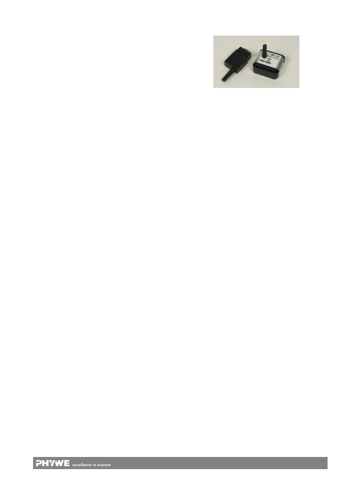
07157-93 Large-scale display, digital
09057-19 XR 4.0 Display-Connect, set of transmitter and
receiver
Fig. 13: XR 4.0 Display Connect module
For display of measured values and device parameters, the
large-scale display can be connected via the Display Connect
set. For this purpose, the TX adapter of the Display Connect
module must be connected to the external socket panel
("Display” socket). The RX adapter must be connected to the
large-scale display. The values are selected via the menu on
the control panel.
Sets
XRE 4.0 X-ray expert set 09110-88
XRW 4.0 X-ray wireless demonstration upgrade set,
09115-88
XRP 4.0 X-ray solid state upgrade set, 09120-88
XRC 4.0 X-ray characteristics upgrade set, 09130-88
XRS 4.0 X-ray structural analysis upgrade set, 09140-88
XRI 4.0 X-ray imaging upgrade set, 09150-88
XRM 4.0 X-ray material analysis upgrade set, 09160-88
XRD
4.0
X-ray
dosimetry
and radiation damage upgrade
set, 09170-88
XRCT 4.0 X-ray Computer Tomography upgrade set,
09180-88
11 WARRANTY
We give a warranty of 24 months for units supplied by us in-
side the EU, and a warranty of 12 months outside the EU.
Any damage that is due to non-compliance with the operating
instructions, improper use, or natural wear is excluded from
the warranty.
The manufacturer can only be held liable for the function and
safety-relevant properties of the unit, if the maintenance, ser-
vice, and modifications of the unit are performed solely by the
manufacturer or by an institution that is expressly authorised
by the manufacturer.
12
www.phywe.com, © All rights reserved
09057-99 / 2115
12 DISPOSAL
The packaging mainly consists of environmentally-friendly
materials that should be returned to the local recycling sta-
tions.
PHYWE Systeme GmbH & Co. KG
Customer Service
Robert-Bosch-Breite 10
37079 Göttingen
Germany
Telephone +49
(0)
551
604-274
Fax +49
(0)
551
604-246
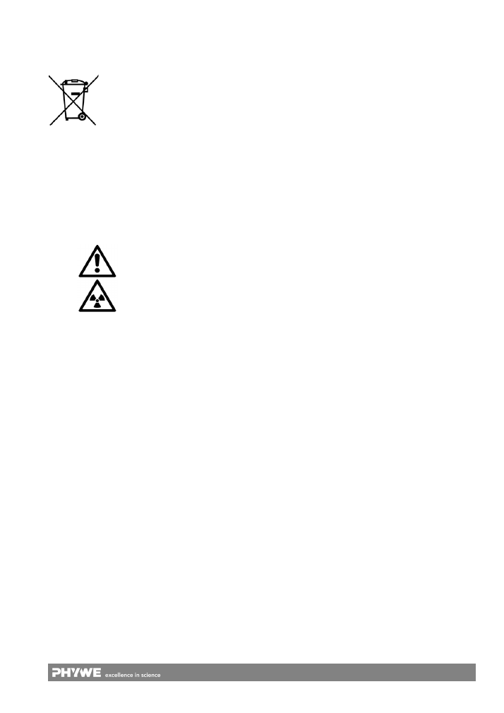
13 APPENDIX
Symbols
Warning
Warning, radioactive sub-
stance or ionising radiation.
Do not dispose of this product with normal
household waste. If this unit needs to be
disposed of, please return it to the address
that is stated below for proper disposal.
13
www.phywe.com, © All rights reserved
09057-99 / 2115
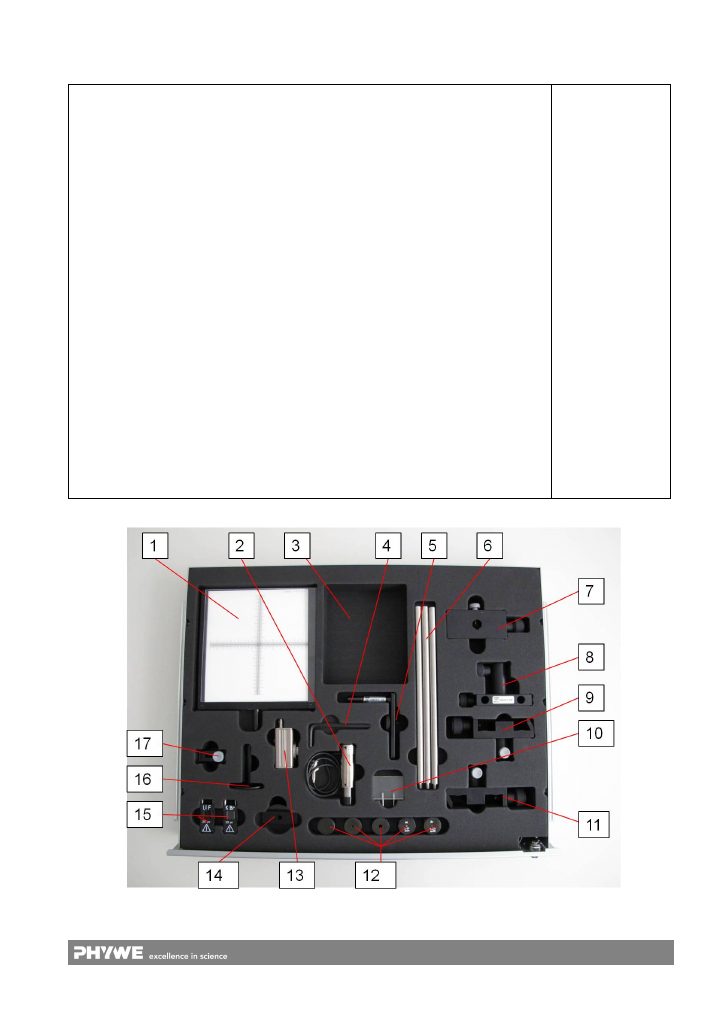
General map to fill the tray for accessories:
space
Art. no.
Name
Included in XRE
1
09057-26
XR 4.0 X-ray fluorescent screen
x
2
09005-00
Counter tube, type B
3
free for e.g. 14608-00 Data cable USB, plug type A/B
x
4 Allen
key
x
5
09057-15
XR 4.0 X-ray Adapter for digital camera
6
09057-21
XR 4.0 X-ray external optical bench
7
08286-00
Slide mount for optical profile-bench
x
8
09057-29
XR 4.0 X-ray slide for external optical bench
9
08286-01
Slide mount for optical bench,
h
= 30
mm x
10
09058-04
XR 4.0 X-ray Compton attachment for x-ray-unit
11
08286-01
Slide mount for optical bench,
h
= 30
mm x
12
09057-01
XR 4.0 X-ray Diaphragm tube
d
= 1
mm
09057-02
XR 4.0 X-ray Diaphragm tube
d
= 2
mm
09057-03
XR 4.0 X-ray Diaphragm tube
d
= 5
mm
09056-03
XR 4.0 X-ray Diaphragm tube with nickel foil
09058-03
XR 4.0 X-ray Diaphragm tube with zr foil
13
09058-30
XR 4.0 X-ray energy detector (XRED)
14
09058-11
XR 4.0 X-ray Crystal holder for Laue-pattern
15
09056-05
XR 4.0 X-ray Lithium fluorid crystal, mounted
09056-01
XR 4.0 X-ray Potassium Bromide Crystal, mounted
16 09824-00
Table
with
stem
x
17
09058-02
XR 4.0 X-ray Universal crystal holder for x-ray-unit