Full Text Searchable PDF User Manual
1
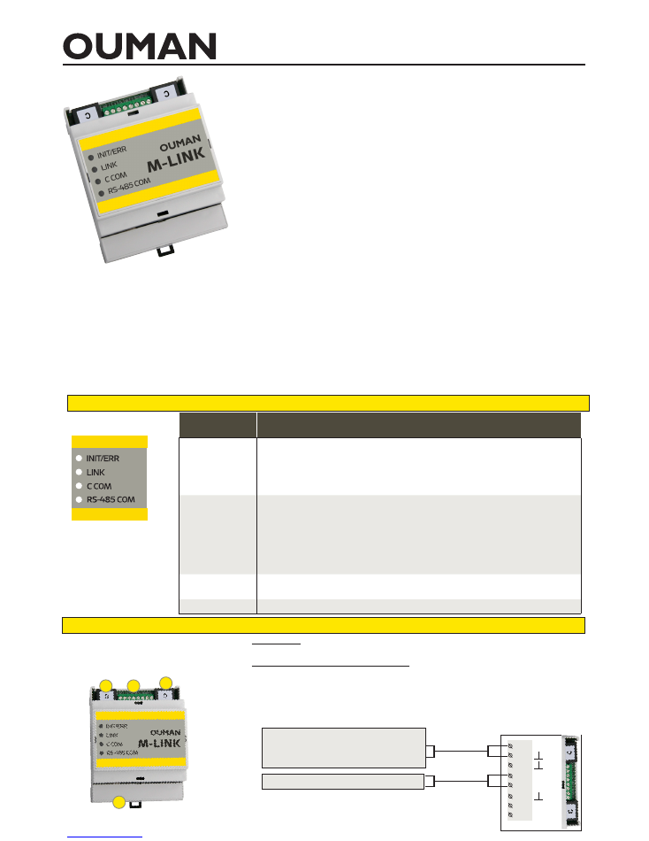
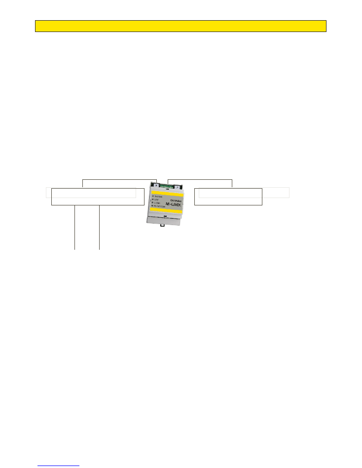
M-LINK
Network adapter with Access function
LED indicator
light
Description of the function
INIT/ERR
•
A red indicator light indicates the status of the device.
•
A red indicator light flashes when the device starts up.
•
The indicator light goes off when the device has been initialized.
•
If the indicator light continues to flash, initializing of the M-Link was not suc-
cessful, or a no response alarm is received from a device in the RTU or C bus.
LINK
•
A green indicator light indicates the status of network connection.
•
When the signal light is off, there is no connection with the LAN.
•
When the signal light is off most of the time but blinks occasionally, the
LAN connection is operational.
•
When the signal light is on almost constantly but is turned off for brief
moments, the Internet connection is operational.
•
When the signal light is constantly on, the Access connection is operational.
C COM
•
When the signal light blinks, M-Link is receiving data from a device
connected in the C connector.
RS-485 COM
•
When the signal light blinks, M-Link is receiving data from the Modbus RTU bus.
LED functions
Installation and connections
Installation:
Fixed on a DIN rail.
Commissioning of M-Link’s connections:
1. The network cable is connected in M-Link’s Ethernet connection.
2. M-Link is connected to the connector of an M-Link-compatible device using a
direct RJ45 cable. M-Link’s power supply is available at this C connector. The
GSM modem of a C203 or S203 device (GSMMOD) is connected to the free C
connector. M-Link’s terminal strips:
2
5
8
3
6
1
4
7
2x0.8
2x(2+1)x0.24
RX
~
B
TX
A
External power supply for M-Link.
An
external power supply is used if no M-Link-
compatible device is connected to M-Link’s C
connector.
Modbus RTU bus
Connectors 7 and 8 are not used
2
2
3
1
M-LINK is a media converter for converting Ouman’s Modbus (RTU / TCP)
based devices, or those of other manufacturers, to the Ouman system. The
device can be linked to an existing internet connection, through which the
device creates a secure connection between M-LINK and the Ouman Ounet
online monitoring service. If an internet connection is not available, it is pos-
sible to use a 3G-MOD4 modem, for example, to establish a ready-to-use
connection to the subject. M-LINK can also be used in a local area network
without an internet connection.
•
An internal WEB user interface for device management: Connected
devices are deployed using the Ouflex BA Tool.
•
Ethernet connection (DHCP / Fixed IP) with
Access function.
Access is a
service offered by Ouman for creating a secure VPN connection between
the device and the Ounet online monitoring service. With the service, the
device can also be operated remotely through an internet browser. The
service is included in the price throughout the device’s life cycle.
•
Modbus RTU connection using screw connectors: (Max 10 devices or
2,000 points, RTU + TCP)
•
Modbus TCP connection RJ45: (Max 10 devices or 2,000 points, RTU + TCP)
•
With a C connector (RJ45), it is also possible to connect (one) Ouman
controller (Ouflex M, Ouflex M BA, S203, C203, H23) + GSM Modem
when using S203 or C203.
•
Possible to make point transfers from one device to another (Modbus
RTU / Modbus TCP) (requires the Ouflex BA Tool)
Communication protocols:
•
Modbus RTU
•
Modbus TCP/IP
2
C
C
C
C
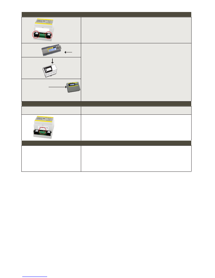
M-Link C connection
These connections are only used with Ouman’s own devices fitted with an RJ45
connector. The C connections are identical. You can connect M-Link-compatible
Ouman device in one connector and a GSM modem (GSMMOD) in the other for
text message communication (C203 and S203 only). When connecting an Ouman
device to a C connector, make sure that Access is on (System settings ->Network
settings -> Access ”On”). For further information, see p. 4.
C203 or
Ouflex C
RJ45
connector
Features
•
Connecting an Ouman device to M-Link interfaces, importing network features
•
Conversion of the registers to Modbus RTU and TCP/IP buses
•
The platform version of a connected Ouman device can be remotely updated
•
Downloading applications via an LAN / remote connection
•
Process monitoring of devices with a Ouflex C platform
•
The power supply of an M-Link device comes from an Ouman device con-
nected in the C connector
Supported Ouman devices:
•
C203 v.1.5.1 (the older versions must be updated to obtain M-Link support)
•
Ouflex C (Platform v. 4.0.0 ->)
•
Ouflex M (Platform v.1.2.0->)
•
Ouflex M BA (Platform v.1.0.0->)
•
S203 (v. 1.2.0 ->)
Ouflex M or
Ouflex M BA
RJ45 connector
S203 or
H23
RJ45-
I
connector
Modbus RTU bus
Older Ouman devices, such as EH-203 and EH-105, as well as third-party devices,
can be connected via this connection.
B A
Features
•
Connecting a device to M-Link interfaces
•
Resetting the alarm registers of EH-203 and EH-105 devices via Ounet
Supported devices
•
All Ouman devices with MB-RTU support
•
All third-party devices with MB-RTU support
Modbus TCP/IP bus
The devices can communicate with the MB TCP/IP network via this connection (the
general network cabling can be utilised).
Features
•
Connecting a device to M-Link interfaces
Supported devices
•
All Ouman devices with MB-TCP/IP support
•
All third-party devices with MB-TCP/IP support
xx.xxx.xx.xx
3
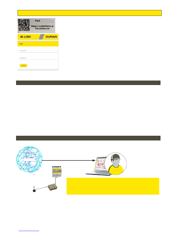
Establishing a browser connection to M-Link
If you have a QR reader, read the QR code in the label on the M-Link de-
vice.
Username = service The password is shown in the label at the end of the
M-Link device. The password can be changed on the “Update” tab. For further
information on browser use, see p. 15
PLEASE NOTE: Do not connect M-Link to the public Internet without
a firewall! If connected without a firewall, the M-Link device can be
exposed to network attacks. Normally a 3G modem, an ADSL/WDSL/
cable modem implements the firewall functionality, making a separate
additional device unnecessary. Change your own login password.
M-Link device in an internal network
M-Link device in a public network
If the device is in an internal network, you can establish a browser con-
nection to the device by reading the QR code or by entering the www
address in the label.
The address is in the format https:// and enter then the web address on the
label so that the “ouman.net” is replaced by text “ouman.local”. For example,
https://m00000735-40rxr.ouman.local
If you do not know the www address of the M-Link device, you
can find the M-Link device in the LAN using the NetworkDis-
covery program. The program is available free of charge from
Ouman Oy.
If the device is in a public network, you can establish a browser connec-
tion to the device by reading the QR code or by entering the Access-IP
address. The address is shown in the label on the M-Link device.
Internet
Browser use requires
logging in.
The password can be
changed.
TSL encryption (Transport Layer Security)
M-LINK
Ethernet
xxxxxxxxx
4
mxxxxxxx-xxxx.ouman.net
mxxxxxxx-xxxx.ouman.net
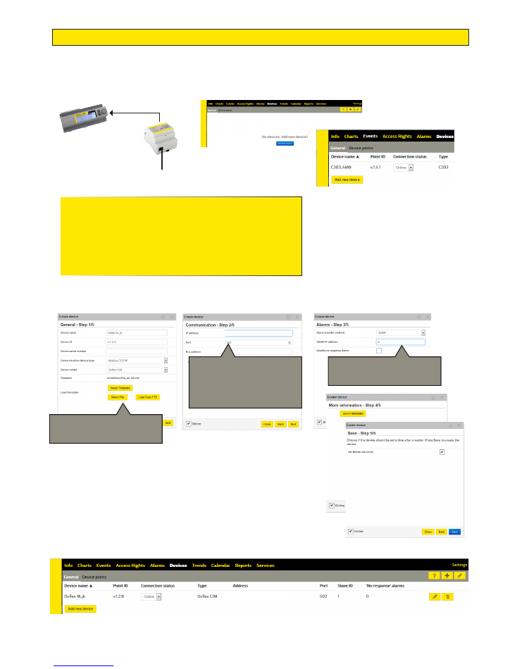
Ounet connection of an Ouman unit controller
When you want to read the information of one M-Link-compatible device in a browser, connect the device directly to M-
Link’s C connector. This also allows you to perform a remote update on the device, if required.
Note: You must also activate the SNMP function from the de-
vice connected in the C contactor
(System settings -> Network settings -> SNMP -> Active “On”.)
RJ45 connector
C203
Ethernet
The power supply
of an M-Link device
comes from a device
connected in the C
connector
M-LINK
Enter the URL as the IP address
(do not enter https: // or www).
Url address can be found on the
sticker on the side of M-Link.
The default port is 502.
If you want to activate the
transfer of SNMP alarms, give the
Device address.
Add the template from the file or
Ounet, or download it from the
device.
When connecting an Ouman device to a C connector, check in the device’s
network settings (System settings) that.
•
The DHCP setting is “ON” (If you change the setting, select “Update
network settings")
•
The port address is the same as in Ounet (Modbus TCP/IP -> Port 502)
•
The Access setting is “ON”
•
In SNMP settings, the Access IP address is given as the IP address,
and “ON” is selected as the “Function on” setting.
C connector
mxxxxxxx-xxxx.ouman.net
5
Connecting several devices to M-Link
Modbus RTU Master
Ouman Device:
C203/S203/H23/Ouflex M/ Ouflex M BA)
C-Serial RJ45 -TCP Port 502
RTU Serial - TCP Port 506
Modbus Slave
Device
M-Link internal r
egisters
T
CP P
ort 505
TCP P
ort 504
Serial 2 (Ouflex M, Ouflex M BA)
Serial 1
TCP P
ort 503
C bus connector / connectors (RJ45)
• You can only connect one Ouman device to one of the RJ45 connector (Ouflex M / Ouflex M BA, S203, C203 or H23).
• M-LINK receives its operating voltage via the connected device. (An external operating voltage source is not requi-
red.)
• The firmware (version) of the device connected via the C bus can be updated remotely, where necessary.
• The application of the device connected via the C bus can be uploaded remotely (Ouflex M BA and Ouflex M, if the
Ouflex M device has a memory card in place).
• Through the device connected to the C bus, you can read Modbus devices that have been connected under it as
Modus RTU slave devices. (Ports 503 & 504)
Modbus RTU (screw connectors)
• It is possible to connect several Modbus devices to the RTU bus (max. 10 devices).
• When M-LINK is the Modbus master device, point transfers can be made between the devices.
6
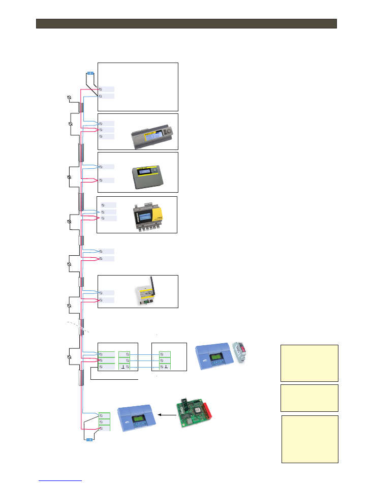
Modbus RTU wiring diagram
If you want to read the data of several devices using a browser, connect the devices to the RTU bus. You can bring bus
devices up to Ounet using the M-Link. We recommend that you connect a maximum of 10 devices to the RTU bus.
A twisted pair cable must be used for network cabling, e.g.,
Datajamak 2x(2+1)x0.24. The network must be like a chain,
with the cable going from one device to the next and stubs are
not recommended (max. length of stub 0.5m). The maximum
length of the whole network is 1200m.
120 ohm terminating
resistors are connected to both ends of the network.
The twisted pair cable’s protective shield can be connected
if needed in to protective earth in order to eliminate inter-
ference. The connection is made only from the other end of
the protective shield, e.g., always from the cable leaving the
controller.
Attention! Ouman Ouflex C devices have the following fac-
tory default settings:
Modbus slave address 10
Baud rate
9600
Data bits
8
Stop bits
1
Paritity
None
If the Modbus-RTU bus has multiple devices, the Modbus
slave addresses must be unique.
Do changes to the controller:
Systen settings-> Network settings-> Modbus RTU settings.
TE (PE)
Datajamak
2 x (2+1) x 0.24
The pr
otective shield extends fr
om one device to the next without a br
eak.
Terminal resisstor
120 ohm
Master device
-M-Link (A,B)
- C203 (A1,B1)
- H23 (A, B)
- S203 (A, B)
- Ouflex M BA (A1, B1)
-
Ouflex M
(A1, B1) or
- WL-Base (A, B)
C203-slave
(all versions)
S203 or H23 -slave
(all versions)
Modbus device
WL-BASE
Ouflex M or Ouflex M BA -slave
23 B1
6 B
B
B
7 B1
6 BG
22 A1
21 BG
3 A
A
A
8 A1
A
B
Terminal resistor
120 ohm
Modbus-100/Modbus-200
Modbus-100-DIN/
Modbus-200-DIN
EH-100/EH-200
EH-100/EH-200
Modbus-100/200
24VAC
EH-105/EH-200
(Take a supply voltage of the Modbus-100/200
device from the regulator (strip connector 41)
MC-
MA+
24~
C
A
C
A
C
B
A
DIP3 DIP4 Baud rate
0 0
4800
1 0
9600
0 1 19200
1 1
38400
DIP1 DIP2 Biasing resistors
0 0
Not in use
1 0
In use
If EH-200/EH-100 is the first
or last device in the bus, bi-
asing resistor must be taken
into use
All participants of the network must have the same baud rate, data bits, stop bits and paritity. EH-
100/EH-200 devices has follow settings: data bits 8, stop bits 1 and paritity “None”.Be sure that de-
vices have unique slave address. The address of EH-200/EH-105 devices will be set by DIP switches
3 and 4.
DIP switches, 1 = ON
DIP 5 DIP 9 = Address
1 0 0 0 0 = 1
0 1 0 0 0 = 2
1 1 0 0 0 = 3
0 0 1 0 0 = 4
1 0 1 0 0 = 5
… … … … … … …
1 1 1 1 1 = 31
(All Ouman devices
and also third party
devices, which have
MB-RTU support)
7
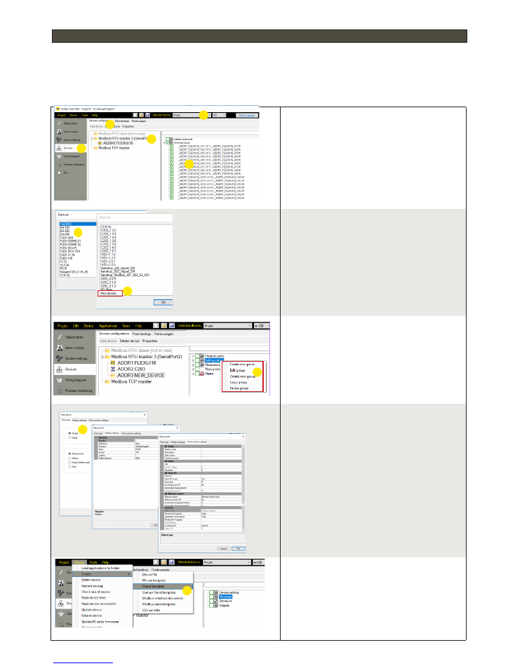
Connecting a bus device to an M-Link device
The M-Link device can read the device points of a device connected to its own Modbus/RTU bus. The device
points may be physical measurement results, settings, controls etc. The read points can be brought up to Ounet
or other SCADA systems or transferred as a point transfer to another device via the TCP/IP bus. The device
whose device points are read, is added as a bus device using the OuflexTool.
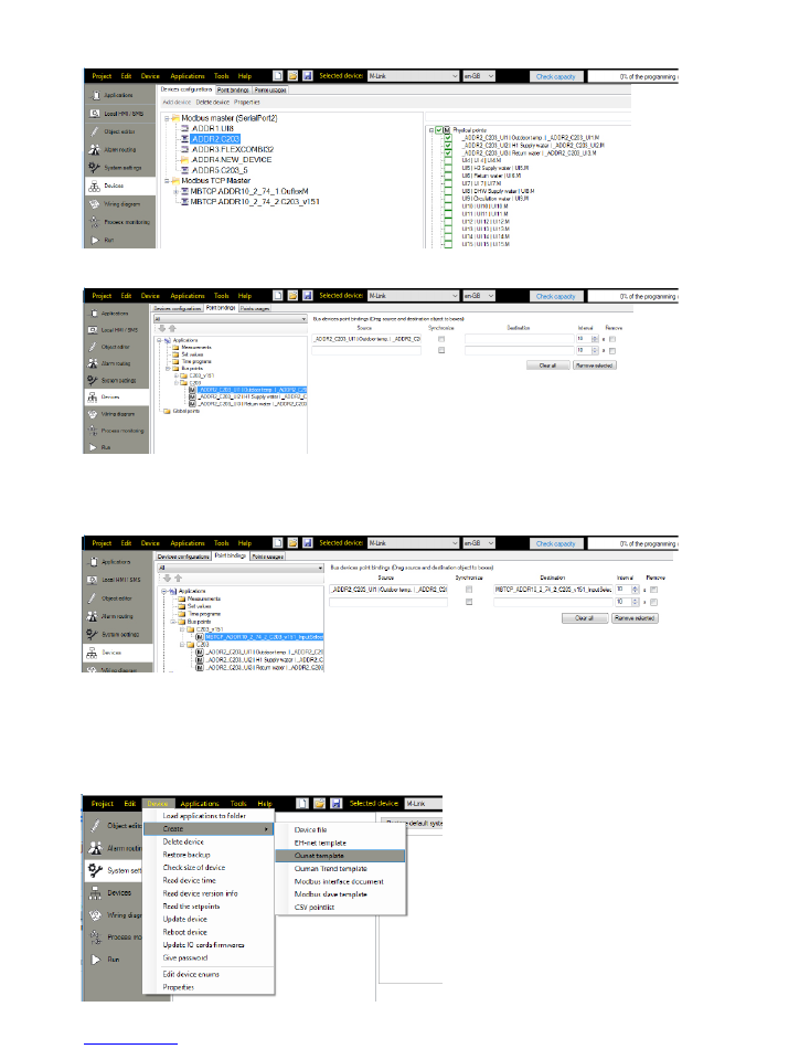
1. Open OuflexTool. Select M-Link.
2. Select “Devices”
3. Select Modbus master (SerialPort2)
4. Select “Add device”.
5. If the device you want to add is on the list,
select the device.
6. Just select points from the list of points you
want to read
7. If the device cannot be found from the list,
select ”New device” -> name the device -> and enter
a unique device address
8
8. Add the new device’s points to the points list.
Create the points for the device by right-clicking a
group in the point list.
9. Fill out the form data, “Point Type,” “Modbus set-
tings,” and “Point common settings”.
10. When the desired Modbus points have been
added, select “Device” tab and then “Create” “ounet
template”. The device can now be brought up to Ou-
net.
10
1
2
4
3
6
5
7
9
7
8
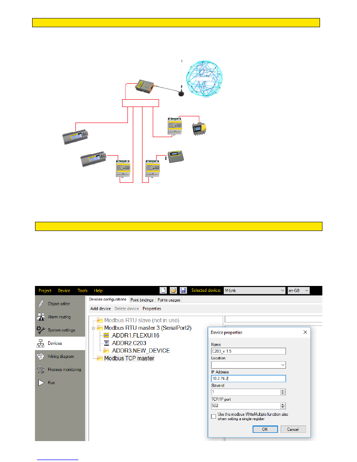
If you want Master devices to communicate with each other, connect the Master devices to the same
subnet. This M-Link device works as a slave device. Modbus TCPIP server and client devices must have
fixed IP.
If you want to do the point transfer between devices, connect devices to the bus of the M-Link.
Add a device you want to write or read through the bus. Enter the IP address. You can read the device
points of another device. Make a point transfer.
C203
Master
Master
Ouflex M or
Ouflex M BA
Ouflex-master
The switch device
Modbus-
TCP
Modbus-TCP
Modbus-
TCP
Internet
Master
S203 tai H23, connector I
Point transfer from device to another
Modbus TCP/IP communication
9
Select the device whose points are to be imported to M-Link.
Points are transferred as follows:
Create a template for the M-Link device and add the device to Ounet (see page 4).
Select the device and its point where you want to read
the source field point. Drag and drop the point to the “Tar-
get” field.
If you select “synchronize”, you can both read and alter
the device point (you can alter the value of the point from
either device).
Select the “Point bindings” tab
Select “Bus points”
Select the device whose point data is to be read.
Select the point you want to read.
Drag and drop the point to the “Source” field.
10
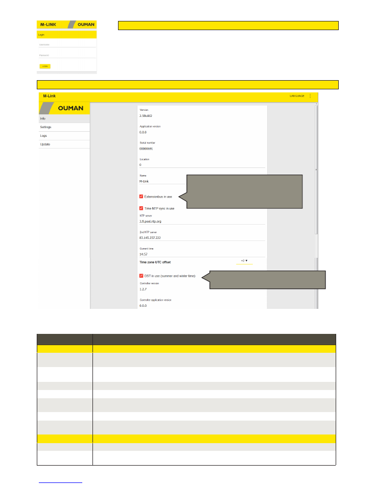
The Info view shows all information on M-Link and the Ouman controller connected to the M-Link via the C connector
Info
Setting
Description
M-Link
Extension bus in use
Information on the status of device connection of the M-Link-compatible device connected to Oulink’s C
connector.
Time NTP sync in use
You can choose whether the clock will be synchronised with the time server. When this selection is made,
the clock of the Ouman device connected in the C connector will also be updated.
NTP server
The time server to which the time is synchronised.
2nd NTP server
Secondary time server, used if connection to the primary time server is lost.
Current time
The device reads the time from the server. The time and calendar details of the controller connected to M-
Link via a C connector will also be updated from the server.
Time zone UTC offset
The current time zone. Finland’s time zone is +2:00.
DST in use
If you select “DST in use”, the device will automatically switch between winter time and daylight saving
time according to the calendar.
Controller
Ouman device connected to an Ouman device via a C connector
Controller version
Device platform version of the Ouman device
Controller application
version
Software version of the control application of the Ouman device
M-Link’s web user interface
Log into the browser view (see p. 2).
DST= Daylight saving time. This selection activates
the winter time / daylight saving time calendar.
If an Ouman device is connected to the C connec-
tor, select “Extension bus in use”. Then M-Link’s
INT/ERR signal lamp will tell the status of the
connection between M-Link and the M-Link-
compatible device.
11
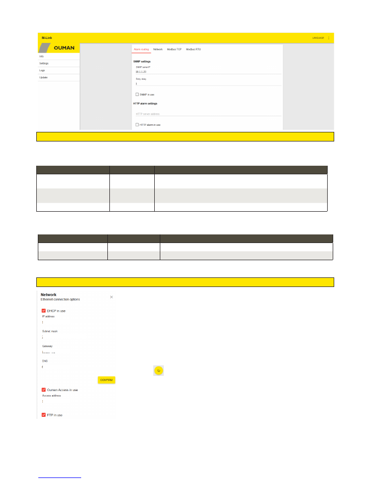
1. You can deactivate the function at “DHCP in use”. (If the DHCP function is on, the
manual changes will be bypassed at IP address , Subnet mask, Gateway address and
Name server address).
2. Ask the network administrator for the network settings and enter the desired settings.
3. Select “Confirm”.
Alternative 2: Setting the IP address manually:
This requires that network has DHCP service that assigns an IP address for
M-Link
.
1. Select “DHCP in use” .
2. Select ”Confirm”.
3. Wait approximately one minute.
4. Select
. If the IP settings changes, the new IP settings have been successfully
received. If the IP settings do not change, make sure the connections are correct and
that the network has a DHCP server.
5. If you select “Ouman Access in use”, M-Link retrieves the Access IP address
1
2
5
There are two alternative ways to set the M-Link device IP address and
network settings:
1. IP address is retrieved via DHCP function.
2. IP address is set manually.
Alternative 1. Setting the IP address via DHCP function:
Settings
Alarm routing:
Network
Setting
Factory setting
Description
SNMP server IP
10.1.1.23
The IP address of the destination server where the message is sent. Ounet’s
IP address 10.1.1.23 is the default.
Retry delay
5 min
If the alarm is not acknowledged from the server, the alarm message will be
resent after the delay that is set.
SNMP in use
This selection enables/disables the entire SNMP function.
The SNMP function can be used for alarm transfers between Ouman devices and the control room.
The SNMP func-
tion can be used for sending information on the activation, elimination and resetting of alarms to the desired server using the SNMP
protocol.
FTP in use:
With FTP enabled, you can download the template file to Ounet directly
from the device (see page 4).
Setting
Factory setting
Description
HTTP server address
The IP address of the destination server where the message is sent.
HTTP alarm in use
This selection activates the sending of alerts via HTTP messages.
Please note: If Access connection is used, M-Link’s Access IP address or name (m
xxxxxxxx
.ouman.net) must also be set at
Ounet as the local IP address.
From the M-link device, information about alarm can also be transmitted using the HTTP protocol.
192.168.1.1
192.168.1.254
255.255.255.0
8.8.8.8
xx.xx.xxx.xxx

12
Setting
Factory
setting
Description (see figure, page 5)
Gateway port 1
(First port of device
that is connected to
C-Serial)
503
A M-Link-compatible device can be connected to M-Link’s C connector as a master device. The
M-Link-compatible device may have one or more RTU buses. The port setting of Modbus master
1 bus is specified here. The Port 1 setting determines the TCP/IP port serving as the gateway to
the Modbus RTU bus of the M-Link- compatible device.
Gateway port
2
(Second port of device
that is connected to
C-Serial)
504
The M-Link-compatible device may have several RTU buses. The port setting of Modbus master
2 bus is specified here. The Port 2 setting determines the TCP/IP port serving as the gateway
to the Modbus RTU bus of the M-Link- compatible device (for example, an Ouflex M device may
have two RTU buses in use (A1, B1 and A2, B2)
Gateway port
3
(Internal registers of
M-LINK)
505
M-Link’s internal register details are read via this port.
Port 4 (Internal re-
gisters of device
that is connected to
C-Serial)
502
Port 4 is reserved for the internal communication of a M-Link-compatible device connected to
M-Link. Information from the Modbus register of a M-Link-compatible device connected to M-
Link is read/written via this port.
Port 5 (Port for de-
vices that has con-
nected to modbus
RTU)
506
M-Link’s own port to the RTU bus (strip terminals 5 (A) and 4 (B). If the port value is 0, port con-
nection is not open.
Slave address for in-
ternal registers
1
When a M-Link-compatible device (Ouflex M, Ouflex M BA, S203, C203, H23) is connected to M-
Link via the C connector as a slave device, the address of the device is set here.
Maximum number of
connections
20
The server load can be changed by changing this setting. The setting determines the maximum
number of allowed simultaneous connections from different IP addresses to the server.
Size of requests
buffer
50
Buffer for TCP requests.
Idle timeout before
connections close
300
This determines the time after which inactive connections are disconnected from the server.
Value 0 means that idle timeout is not in use.
Allowed client add-
ress
0.0.0.0
The data security of the system can be improved by activating the allowed client address func-
tion. If the value is 0.0.0.0, connections from any IP address to the server are enabled. When you
specify a certain connection address, only contacts from the specified IP address are allowed.
Refresh view.
1. LAN is routed via Internet
The Access service operates on the Internet so the Access service is not available if the device is not connected to the Internet. The
Access device examines the availability of Internet connection by sending a Ping packet to the Internet server at 3-minute intervals.
The network must allow the ICMP outwards from any port and the receipt of the reply message to the same port.
2. The VPN protocol used by Access service outwards is not blocked
The Access service is based on the VPN connection which the Access device creates to the Access server.
The network must allow the UDP outwards from any port to the port 1194 and the receipt of the reply message to this port.
3. Time service protocol outwards is not blocked
The Access service works only when the clock in the Access device shows the correct time. The clock is set to the correct time from
the network using the NTP protocol.
The network must allow the UDP outwards from any port to the port 123 and the receipt of the reply message to this port.
Access service requirements
Modbus TCP
Modbus TCP/IP settings are used to change the Modbus TCP server settings. The Modbus TCP/IP in-
terface can be used for communication with Modbus/RTU slave devices connected to the device.
13
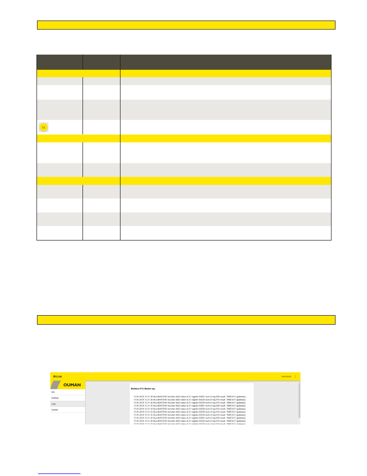
Modbus RTU
Setting
Factory
setting
Description
Modbus master settings
These settings are in use when “Master” is selected as the function of the M-Link device
Timeout
1000 ms
Modbus master timeout
Min delay
between packets
100 ms
Minimum delay between packets. If a device in the bus is unstable, bus traffic can be restored
by increasing the delay between packets.
Timeouts to fault
state
5
This setting determines the number of unanswered requests made to a slave device before
changing the state of the device to fault state. A signal strength alarm is raised when the in-
coming delay time has passed while the fault state was active.
Refresh view.
Modbus RTU slave settings
Function in use
The M-Link device can be on the bus either as a master device or as a slave device. Configu-
ring M-Link as a slave requires OuflexTool programming. In this case, master-points from the
third party device are read by means of M-Link to Ounet.
Slave address for
internal registers
1
Serial port (A1,B1) settings
Port baudrate
9600
Speed of traffic in the bus. The devices connected to the same bus must have the same traffic
speed (baud rate). The default rate is 9600 bauds, but it can be changed.
Data bits
8
Number of data bits in the bus. The devices connected to the same bus must have the same
Data bits value.
Parity
None
Parity of the bus. None = parity is not taken into account. Set the same parity as here for all
devices in the bus.
Stop bits
1
Number of stop bits in the bus. The devices connected to the same serial port must have the
same Stop bits setting.
M-LINK has a free TCP/RTU gateway. You can read the measurement point data of any RTU slave device via Ounet.
You can also add bus devices to M-LINK.
Logs
When you click the “Update log”, 50 latest descriptions of bus communication errors are updated to the screen. Errors may occur in ga-
teway traffic or communication of the Master device. The log shows a time stamp indicating the time the error message was received,
the function it concerns, the slave device register the error is present in, how many items of register data the register contains, and
where the error shows up.
14
Setting
Description
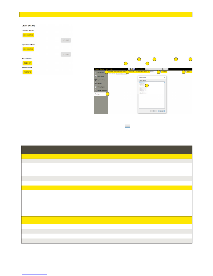
Device (M-Link)
Firmware update
Updating the firmware of M-Link device. An img file is downloaded to the device
Application update
Update of M-Link’s control application: Select the compressed zip folder and then select “Upload”.
The M-Link can unzip the compressed folder. Aplication can be updated also online using the Ouflex-
Tool tool.
Reboot device
Rebooting of the M-Link device
Restore default
Restore factory settings.
Controller
This is a controller connected to the C connector of the M-Link device.
Firmware update
Application update
Reboot controller
Restore default
Remote update of the controller
requires that the controller has a memory card in place and the
controller platform is v. 1.2.3 or later. H23 controllers have memory card readers starting from version
2.0.0 which is why older H23 devices cannot be remotely updated via M-Link.
The devices with an Ouflex C platform can be updated starting from version 4.1.1.
When performing the update, you can decide whether the controller settings are kept (Keep set val-
ues) or are factory settings restored (Clear set values). You can also cancel the update (Cancel updat-
ing).
Change password
You can change the password of the M-Link device. Username = service, and the password (pwd) is
shown in the label at the end of the M-Link device
Current password
Enter the current password in the “Current password” field.
New password
Enter the new password in the “New password” field.
Confirm password
Re-enter the new password
Change
The new password is activated when you click on “Change password”.
Update
Remote update of the controller using the OuflexTool
Make the following selections:
1
“Run” ->
2
To: Online ->
3
scan->
4
Select the address ->
5
“Connect” ->
6
“Load applications to device”
The tool allows specifying whether the firmware is also updated in
conjunction with the application update. The selection is made at
“System settings” ->
Additional system settings: Downloading
files/ Device firmware file. If you select “True”, the firmware is updated
in conjunction with the application update.
In the Update tab, you can perform updates of the M-Link device and
the device connected to M-Link’s C connector and restore factory
settings. The password can also be changed in the Update tab.
The devices can also be updated using the Ouflex BA Tool.
1
2
3
5
6
4

15
Examples of use
• Introduces Access connections to Ouman’s and third parties’ devices, enables con-
nection to Ounet
• Third-party devices can be brought up to the Ounet
• Allows connecting Modbus RTU devices over a Modbus TCP/IP network, and vice
versa
• Different bus point transfers can be made from one device to the next, for example,
reading the outdoor temperature to the EH-203 and the EH-105 via the RTU bus
• Use of I/O cards over a TCP / IP network
• Update of C- and M-based devices, and remote downloading of software
16
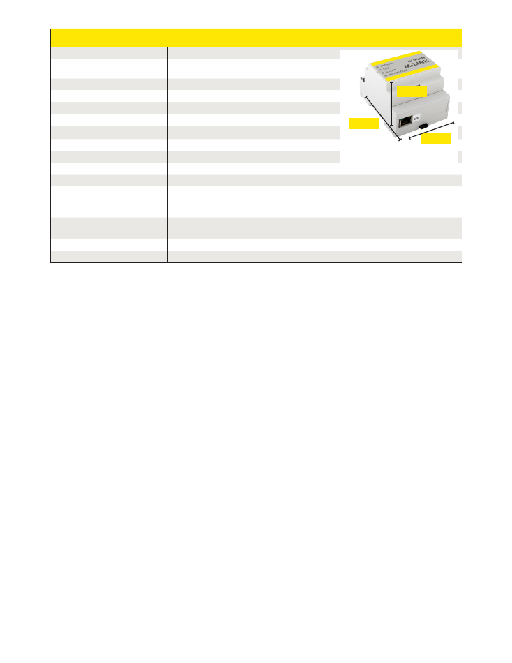
M-LINK
Technical information
Casing
PC/ABS
Mounting
DIN rail
Dimensions
71 mm (4M) x 91 mm x 59 mm
Weight
100 g
Operating temperature
0 ... +50 °C.
Storage temperature
-20 ... +70 °C.
Protection class
IP 20
Ethernet connection
10/100 Mb/s Ethernet-connection (RJ-45)
Serial connections
RS-232, RS-485 Modbus- RTU
Operating voltage
16-30 VDC /1.4 W or 24 VAC (-20% ... +25%) / 3.6 VA
Ethernet protocols
Modbus TCP, HTTP, SNMP and FTP
Approvals
- EMC Interference tolerance
- EMC Interference emissions
EN 61000-6-1
EN 61000-6-3
System dependency
Can be connected to Ounet.
Modbus TCP/IP support
Warranty
2 years
Manufacturer
Ouman Oy
XM1368_M-Link_User manual_v.2.5.0_ENG_20180918
91 mm
71 mm
(4M)
59 mm
We reserve the right to make changes to our products without a special notice.