Full Text Searchable PDF User Manual
NECTA SPA TECHNICAL MANUAL
“
SFERA
“
Manual
“ SFERA”
1 /
19
SERVICE MANUAL
“ SFERA ”
BASIC TECHNICAL MANUAL
THE CONTENTS OF THIS DOCUMENT ARE INTENDED FOR NECTA’S AFTER SALES PERSONNEL.
AFTER SALES SERVICE
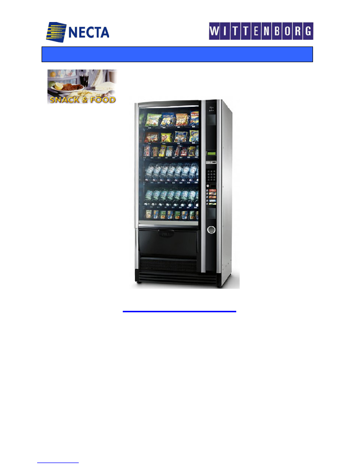
Snack & Food
NECTA SPA TECHNICAL MANUAL
“
SFERA
“
Manual
“ SFERA”
2 /
19
NOTE
The above systems and functional units are specific to this machine.
All functional units installed but not listed in this document, are also used in other machines in the same range;
therefore they will be described in a separate manual for machines belonging to the same range, where all base
functional units will be described more in detail.
Sfera:
View of user interface
TABLE OF CONTENTS
1
2
3
4
5
6
7
8
9
Layout - Models
Electrical systems, connections and configuration
Vending systems
Power supply and Wiring
Cooling unit
Cabinet and Door
Trouble-shooting
HACCP directive (Use instructions)
Periodical cleaning and hygiene
( Daily – Weekly – Yearly )
Pages 3-4-5
Pages 6-7-8-9-10
Page 10
Page 12
Page 13
Page 14
Pages 15 -16
Page 17
Pages 18 -19
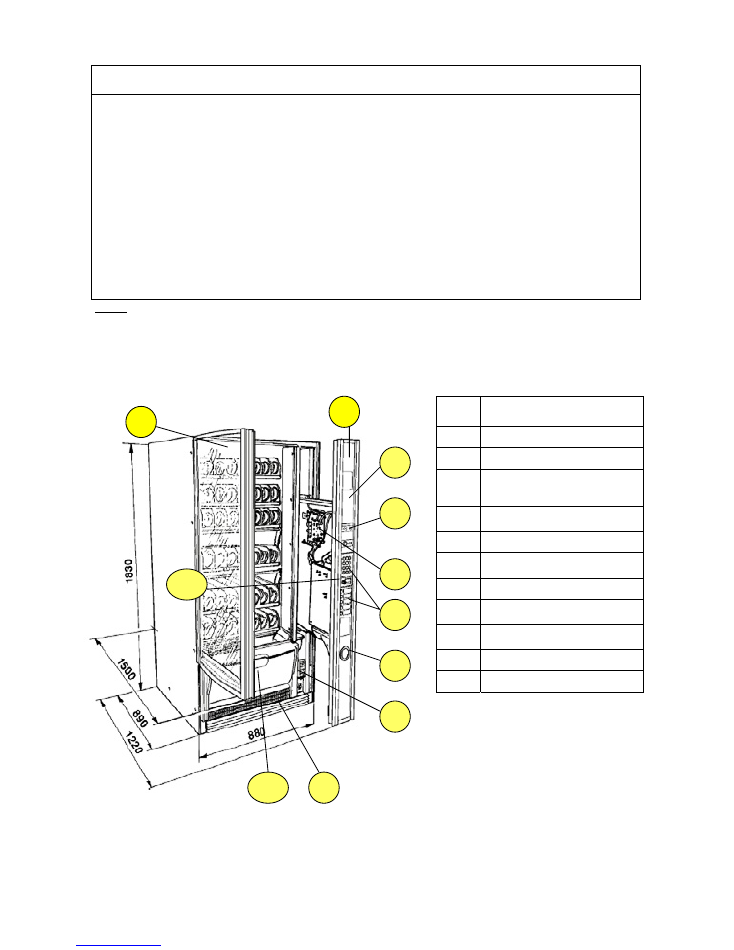
Ref.
DESCRIPTION
1
Rounded glass door
2
Advertising spaces
3
Compartment pre-set for key-type
payment systems or other
systems
4
Machine status information
display
5
CPU board
6
Double keypad with direct and
numeric selection
7
Coin return compartment
8
Power supply unit / fuses / door
safety switch
9
Removable grille for cleaning the
condenser’s filter
10
Product dispensing compartment
11
Key lock
1
2
8
4
1
2
7
6
5
3
8
4
9
10
11
NECTA SPA TECHNICAL MANUAL
“
SFERA
“
Manual
“ SFERA”
3 /
19
1 – LAYOUT - MODELS
Example of Sfera model’s codification
Layout Italy - Version
6-40R / I LX
Meaning
:
SFERA
with
6
trays for a total of
40
selections
Refrigerated version
R
(a non refrigerated version is also available)
Country
: Italy
I
Approved by
IMQ
Q
NB 1:
(if the letter Q is not present it means that such version is not approved by IMQ, or that it is awaiting
approval
Version
LX
-
Model with double keypad (Numeric and direct for five advertised selections)
NB2: without such code, the machine is supplied with only the 12-button numeric keypad
DESCRIPTION
VARIABLES
TRAYS
Up to 6 max
HEIGHT 0F TRAYS
96 mm min and up to 219 mm
max
PARTITIONS PER
TRAY
2 triple + 1 double (or 2 singles)
4 doubles
8 singles
PRICES PER TRAY
One for each selection
TIME BANDS
Available for configuration
PAYMENT SYSTEMS
Serial – EXE- as standard feature
MDB – BDV – with additional board
VEND SYSTEMS
With single and double spiral
DIMENSIONS
H 1830 x L880 x D 890
WEIGHT
-----
OVERALL
DIMENSION
(with door open)
H 1830 x L 880 x D1 1500
LAMP
1 x 36 W (Flourescent/Neon)
ABSORBED POWER 510 W
Numeric
keypad
5-selection
direct
NECTA SPA TECHNICAL MANUAL
“
SFERA
“
Manual
“ SFERA”
4 /
19
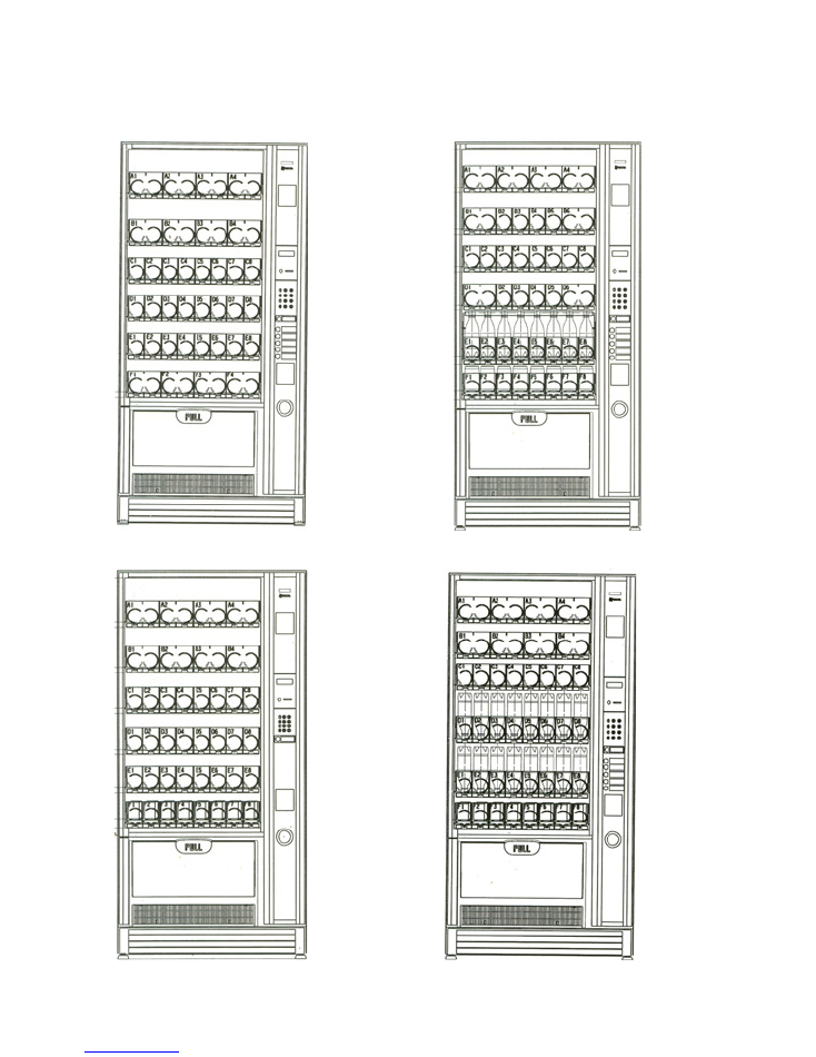
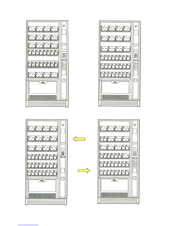
Examples of different tray configurations and positions.
The examples correspond to real layouts (the code is indicated on the side); in any case there are many
configurations options with simple and quick change operations.
Release spirals with different pitches are provided, as indicated in the user manual
Sfera 6 – 40 R/F
Sfera 6 – 36 R/F
Sfera 6 – 36 R/I
Versions provided
for the French
market
Sfera 6 – 40 R/I LX
Versions provided
for the Italian
market
NECTA SPA TECHNICAL MANUAL
“
SFERA
“
Manual
“ SFERA”
5 /
19
Sfera 6 – 36R / B
Sfera 6 – 36R/UK
Sfera 6 – 32R / E
Sfera 6 – 36R / D
Version provided
for Spain
Version provided
for Belgium
Version provided
for Germany
NECTA SPA TECHNICAL MANUAL
“
SFERA
“
Manual
“ SFERA”
6 /
19
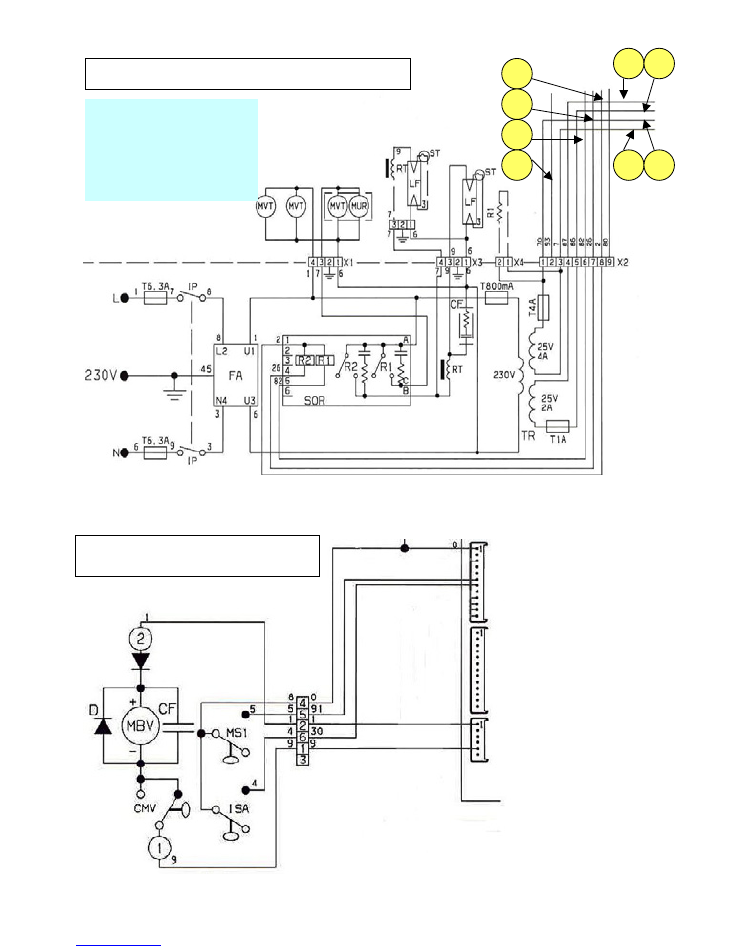
2 - ELECTRICAL SYSTEMS - CONNECTIONS - CONFIGURATIONS
The machine is designed to operate under a single-phase voltage of
230 V AC (+5-10V)
It is protected with
two
T 6,3 A
fuses on both phases.
A safety transformer supplies power to very-low voltage components
(24 V DC),
while the cooling unit and
the Flourescent lamp are powered with the mains voltage.
With regard to the safety transformer:
The primary winding is protected with a
T 800 mA fuse
The secondary winding 25 V is protected with the following fuses::
T 1 A – T 4 A
The slide-out compartment door is fitted with a bipolar safety switch.
The switch is located on the front panel of the power supply unit, and when opening the compartment it
disconnects the power from all parts that can be accessed for normal maintenance and cleaning operations.
The only parts that stay energised are those protected by suitable covers carrying a plate with the warning
"
Disconnect power before removing the cover
”; to clear the voltage the power the power supply cable
must be disconnected from power outlet
or in the case of connection to a dedicated power board, it should
be set to
OFF
The power cable can be supplied as standard feature and chosen
among the following types:
HO5 RN – F copper with a 3 x 1.5 mm
2
section
1)
HO5 VV – F ,, ,, ,, ,,
2)
HO7 RN – F ,, ,, ,, ,,
In all configurations the cable is fitted with a
SCHUKO
plug
permanently fixed to the cable
NOTE :
In the event of replacement cables of exactly the same
characteristics must be used.
Since the “SFERA” vending machine is approved by an
electrical safety certification institute (IMQ), replacements
with non-original components are not permitted.
Otherwise the electrical safety certificate and the warranty will
be void.
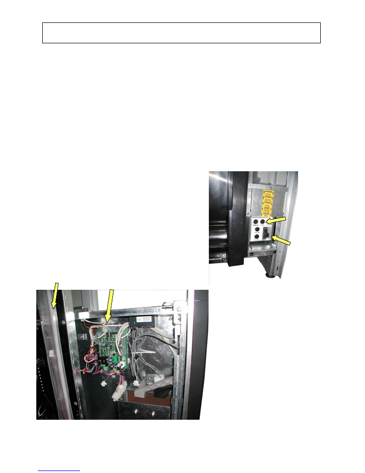
ACTUATION BOARD AND CONNECTIONS
(Electrical compartment open)
A flourescente lamp is located vertically on the right-
hand side inside the cabinet; the starter is fitted
inside the lamp holder. (see page 12)
The ballast is located inside the power supply
compartment.
The CPU board controls also the 24 V actuations by
means of TRIACs and Darlington switches, while the
lamp and the cooling unit are controlled by a relay
card located inside the power supply compartment.
(see page 12)
Some versions are provided with monitoring of the
selected product fall into the dispensing
compartment by means of a card with
receiver/transmitter diodes (infrared).
If during a selection the barrier is not interrupted it
means that a product is finished or jammed, in this
case the system will further attempt releasing the
product with small rotations; if also this fails the
selection is disabled and the customer is entitled to a
new selection.
CPU board and connections
Fluorescent lamp compartment
Protection
fuses
bipolar safety
switch
NECTA SPA TECHNICAL MANUAL
“
SFERA
“
Manual
“ SFERA”
7 /
19
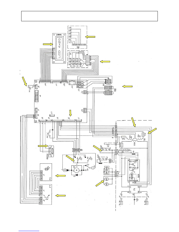
2.1 – CONNECTIONS, BOARD, WIRING DIAGRAMS
D
IRECT SELECTION PUSH
-
BUTTON CARD
N
UMERIC SELECTION
PUSH
-
BUTTON CARD
LCD display Board
Payment system
connections
NTC Probe
Cooling unit
control
J12
R
ATIOMOTOR
CONNECTIONS
P
OWER SUPPLY UNIT
CPU
(C
ENTRAL
P
ROCESSING
U
NIT
)
BOARD
RS232
PORT
-
P
RINTER
,
P
ROGRAMMER
,
PC
Phototransistor card
Receiver
Transmitter
photodiode card
P
OWER SUPPLY
:
230 V 50 H
Z
C
OOLING UNIT
CONTROL CARD
F
LUORESCENT LAMP
CONTROL
T
RANSFORMER
C
ONTROL OF
SLIDER LOCK KIT
CONNECTIONS CPU
BOARD
NECTA SPA TECHNICAL MANUAL
“
SFERA
“
Manual
“ SFERA”
8 /
19
CPU BOARD( SUC)
N° rif.
COMPONENT DESCRIPTION
N° rif.
COMPONENT DESCRIPTION
1
Coin mechanism power supply connector
11
CAN BUS connector
2
Board power supply connector
12
Validator connector
3
GREEN LED
( DL2)
13
NTC sensor connector
4
YELLOW LED
5 V dc ( DL1)
14
LCD display connector
5
Connector for push-button panel LED’s
15
LED RED
6
Spiral ratiomotor control connector
16
Configuration minidip SW2 (will be eliminated)
7
RED LED
reset CPU
17
Selection push-button panel connector
8
Input/output connector
18
Expansion board connector for MDB
9
Connector not used
19
Coin mechanism setting minidips
10
Programmer device connector
20
Expansion board connector for BDV / EXE
CPU BOARD
LAYOUT
COLOURED LED FUNCTIONS
GREEN LED
blinking during the normal operation
YELLOW LED
It glows when 5 V DC is present in the board
RED LED
it glows when the software is reset
(program
malfunction)
Minidip functions 1-4
REF.(20)
Coin mechanism setting 2-3
By default set to OFF
Minidip 1-8
(16)
Default configuration setting fixed to OFF
Both minidips will be eliminated in the near
future, therefore since now the configuration
is only via software setting.
The CPU board is housed inside the payment
system compartment, on the sliding door, and
includes all low-voltage (24 V DC) actuations,
it controls the display, the push-button card,
the photodiode barrier, the payment system
and the NTC probe that monitors that cooling
unit temperature.
The software is written in a Flash EPROM that,
by means of a special program, can be
rewritten and updated without replacing.
It is powered from the power supply unit
through connection J15 (ref. 2)
The photodiode barrier is supplied as standard
feature in some versions, or as an after-sales
kit.
NECTA SPA TECHNICAL MANUAL
“
SFERA
“
Manual
“ SFERA”
9 /
19
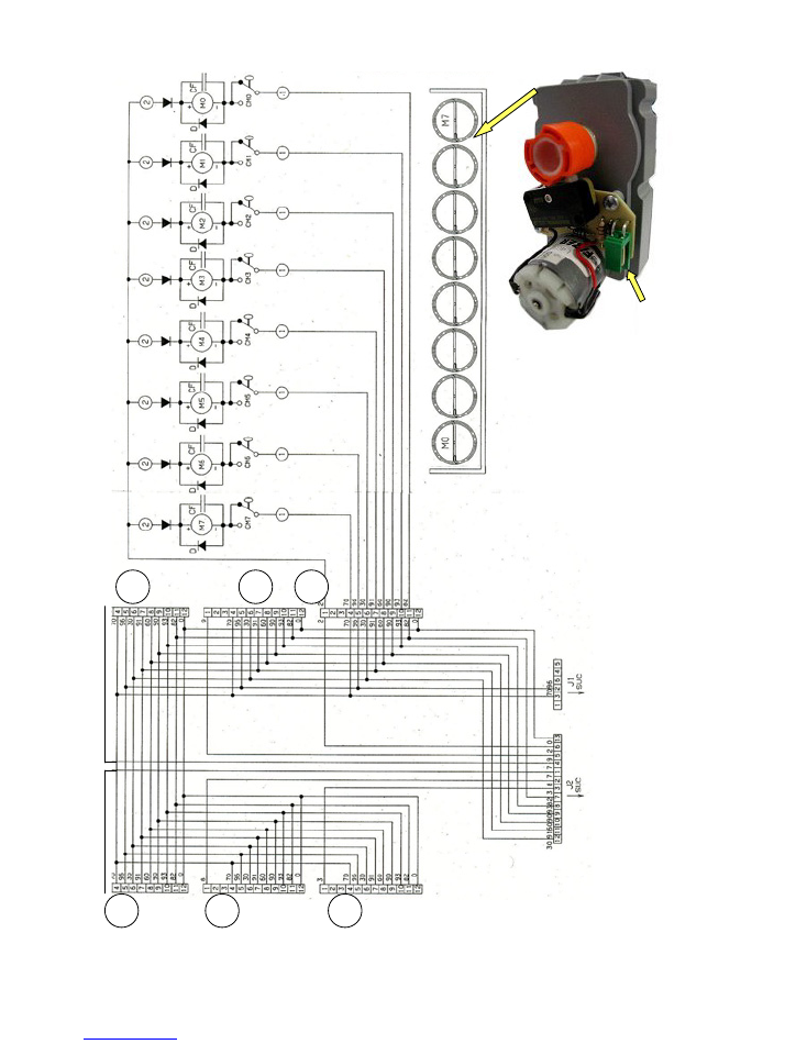
TRAY CONNECTION WIRING DIAGRAM
CONNECTOR
Detail of spiral control ratiomotor
To connector
J 12
CPU board
4
5
1
6
3
2
NECTA SPA TECHNICAL MANUAL
“
SFERA
“
Manual
“ SFERA”
10 /
19
POWER SUPPLY AND LIGHTING DIAGRAM
2
1
3
4
5
6
7
Wiring diagram of dispensing
compartment slider lock device kit
1 – 2
Power supply - EXE
3 – 4
Connector
J14
- 24 V DC
CPU board power supply
5-6-7-8
Connector
J3
IN / OUT to
CPU
8
J 3
J 2
J 1
NECTA SPA TECHNICAL MANUAL
“
SFERA
“
Manual
“ SFERA”
11 /
19
3 – VENDING SYSTEMS
“Sfera” is a vending machine belonging to the S&F range, with
product dispensing by means of the rotation of spirals.
During their rotation the steel spirals, because of their
“auger
effect”
, push forward the product loaded onto the tray,
dropping it in the dispensing compartment.
As an optional kit on request, some versions are provided with
infrared barriers with receiver/transmitter diodes and transistors
that detect the falling product and signal to the software that
the product was released correctly. In the event the barrier is
not interrupted, the option of trying the selection again is given;
if the selection fails again, the option of another choice or
refund is given. (SW option)
The tray is modular, and by simply moving the partitions it is
possible to change it from single to double or triple; there are
also some specific accessories for dispensing special products.
Different pitch spirals are provided, to be able to dispense 20 to
76 mm wide products.
In addition the spirals can be right or left hand, to be used in
double compartment configuration with double spiral. The
ratiomotor is fitted with a “minidip” switch to reverse the
rotation.
The tray is held into position automatically by a stop located on
the guides; to slide out the tray it need to be lifted slightly from
the front and then pulled fully to the second safety stop. To
extract it completely it needs to be lifted further and then
removed (after disconnecting the electrical connector located on
the right side). As standard feature, the vending machine is
provided with 6 trays, however up to 8 trays can be fitted by
reducing the space between trays
(see configuration instructions).
S
PIRALS ROTATION RATIOMOTOR
1
2
3
4
1 - Limit microswitch control cam
2 - Microswitch
3 - Motor control card
4 - Motor
Tray with configuration of 8 single sectors
- View from ratiomotors side
Tray with configuration of 8 single sectors
- View while being removed
Useful pitch:
20, 26, 30, 36, 42, 50, 60, 76
right and left rotation
20
Right-hand 180° rotation with central partition for dispensing
sticks
Availability of spiral pitches and
direction of rotation
NECTA SPA TECHNICAL MANUAL
“
SFERA
“
Manual
“ SFERA”
12 /
19
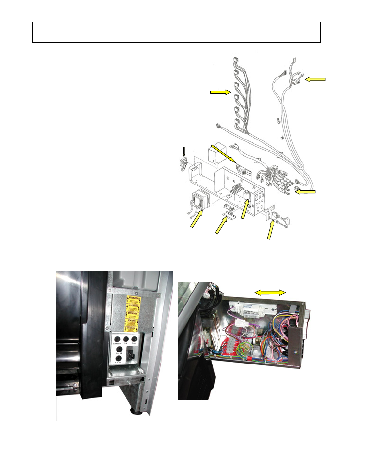
4 - POWER SUPPLY AND WIRING
Like all other NECTA products, the “SFERA” vending
machine is type-approved (or awaiting approval) by IMQ,
therefore all components and electric units are certified as
conforming to European directives, and all cables are fully
sheathed and provided with double insulation. The door
cables are sectioned and fitted with special connectors to
facilitate disassembly of the door.
All connectors for the vending machine control function
branch out from the power supply unit: Keypads, payment
systems, ratiomotors, heating elements, display, cooling
units, electronic cards.
The power supply unit transforms the grid electricity to 24 V
AC and the CPU board acts as rectifier and controller of
actuations to the power users.
All actuations are under extra-low safety voltage, while the
lamps and the cooling unit are controlled by means of
special relay cards at the grid voltage.
The power supply unit is housed in a removable galvanised
steel metal box for greater accessibility.
When opening the door a safety switch is deactivated,
disconnecting the power from all accessible parts.
The unit is protected by electrical interference suppressor
systems in conformity with the European directives.
The power supply unit houses a safety transformer for the
extra-low voltage, the grid fuses, the transformer secondary
winding fuses, the fluorescent lamps ballasts, the relay card
for controlling the cooling unit, the noise interference
suppressors and the safety switch.
Vending trays
connectors
Connectors to
the door
Main
connectors
and fuses
Safety
transformer
Bipolar safety
switch
Lamps
ballasts
Radio
interference
suppressor
Power cable
input from
the mains
Power supply unit being removed
Power supply unit in operating
position showing fuses and safety
switch with protective casing
Cooling unit
control relay
card
NECTA SPA TECHNICAL MANUAL
“
SFERA
“
Manual
“ SFERA”
13 /
19
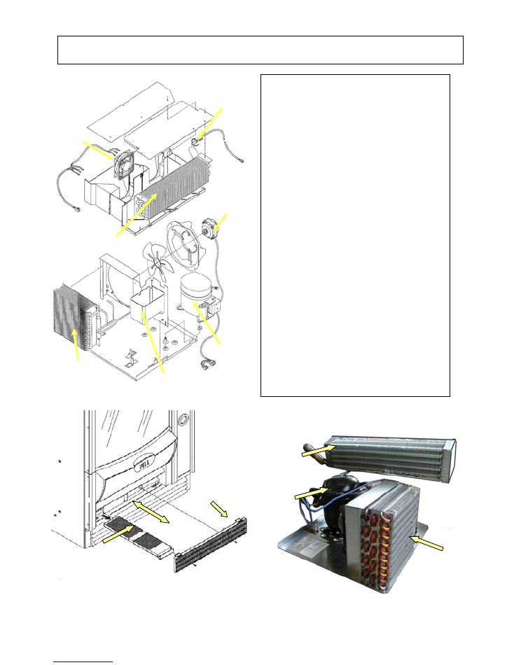
5- COOLING UNIT
The internal temperature controlled by means of an
NTC
type electronic, controlling a traditional type cooling unit,
but with design features that will bring it to the top of
what is currently available on the market.
Yje NTC probe has an internal resistance that varies
according to the ambient temperature change.
At the temperature of 0° C it is 2612 Ohm
At the temperature of 3° C it is 2267 Ohm
At the temperature of 30°C it is 733 Ohm
This way the software controls the unit switching on and
off with extreme accuracy.
The unit is controlled by means of a relay card located in
the power supply unit (SOR card).
When the machine is switched on, the software reads the
value (in Ohm) from the NTC probe and, according to that
value, sends a signal to the relay card that activates or
deactivates the cooling unit operation.
The cooling unit is very compact, with the air intake for the
condenser cooling from the lower part of the base through
a filter that removes the dust; such filter is accessible and
easy to remove for cleaning FIG. 2. The cooling air is
expelled from the front side through the lower grille,
allowing installation in a bank of machines or in a small
space without causing problems to the cooling unit.
In order to completely remove the cooling unit the
dispensing compartment assembly has to be removed
(quick and simple operation), therefore remove the
fastening screws from the unit and support the evaporator
during the extraction operation, ensuring that the power
cable and the power supply unit connector are
disconnected. FIG 3
The control software has the option of setting switching on
time periods, or the safety temperature. See specific
programming manual for further details. It is possible to
set the first two trays with a temperature suitable for
perishable food products.
FIG. 2
Condensation dust
removing filter
Removable
external grille
FIG. 3
Perspective view of cooling unit
Evaporator
Condenser
Compressor
Evaporator
Condenser
FIG. 1
Compressor
Fan
Liquid waste container
NTC Probe
Evaporator fan
NECTA SPA TECHNICAL MANUAL
“
SFERA
“
Manual
“ SFERA”
14 /
19
6– CABINET AND DOOR
Porta vetrata
The cabinet is made of pre-varnished sheet-metal, assembled with rivets
and various reinforcements; pre-formed polystyrene foam insulation
panels are placed between the external pre-varnished sheet-metal part
and the internal refrigerated box part.
The advantage of this solution, compared to the injected polyurethane
foam insulation, is mainly form an environmental point of view, as in
the event of future scrapping of the machine, the cabinet can be
disassembled completely without any complications . ( almost
impossible in the case of cabinet injected with foam and welded)
The base is made from sturdy sheeting, welded and varnished to obtain
greater stability. The feet are adjustable for perfect levelling. By
removing the lower grille a regular trans-pallet can be used for routine
moviment of the machine.
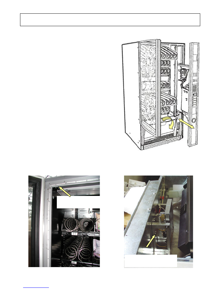
The SFERA is provided with two opening systems: main door and side
sliding compartment.
The main door, for loading products, is a glass front type with double
glazing.
The handle for opening is part of the perimeter profile of the frame,
and locking is by means of a single lock located inside the sliding
compartment on the right.
A sliding compartment is located on the front right side, with the user
interface integrated on its front panel; the CPU board and the payment
system compartment are fitted inside on the central wall.
The following are fitted on the front panel (user interface) : the main
display, the coin slot and the coin return button, the selection keypad
and the lock, that as well as ensuring a three-point lock it keeps the
glass door closed.
The sliding compartment is protected by a safety switch that
disconnects the 230 V AC power, leaving anyway the option of
operating in programming mode by inserting the special key in the
safety switch slot.
The dispensing compartment, with hinged hatch opened from the
upper side, is located on the lower base; such compartment is fitted
with an anti-theft device and anti-vandalism system that will keep it
closed when no selections are made, permitting opening only during a
selection.
Before opening the glass door the sliding door, provided
with a lock, must be opened. To close everything proceed
in the reverse order, i.e. close the glass door, then push
the sliding compartment into position and lock with the
key.
Detail of polystyrene foam insulation
and assembly with rivets
Detail of anti-vandalism closing
mechanism (Kit on request)
NECTA SPA TECHNICAL MANUAL
“
SFERA
“
Manual
“ SFERA”
15 /
19
PROBLEM
(and/or indication on the
display)
POSSIBLE CAUSE
SOLUTION
The display indicates the
message:
“Compressor”
If the compressor runs for 24 hours
consecutively without the cabinet reaching
the temperature set via the SW, the machine
is locked and the selection disabled.
The following could be the cause:
Lack of gas in the refrigeration circuit due to
possible leaks.
Failure to the evaporator’s electric fan.
Failure to the condenser’s electric fan or PTC
triggered.
Clogged lower and/or side grille
Failed probe (in this case the message “probe
failure” will be displayed)
Normally two to four hours are required to
reach the operating temperature
(according to the load). A longer time
means that there is a malfunction: check
for any small leaks in the refrigerating gas
circuit; if necessary repair the leak and
charge with the correct dose of gas.
Check that the electric fans work correctly.
Check for the correct cooling airflow inside
the refrigerated box. In the case of failure
to components, replace with original parts.
The display indicates the
message
“Coin mechanism”
If the CPU for more than 30 seconds does
not receive communication impulses from an
Executive serial coin mechanism, or 75
seconds from a BDV serial coin mechanism,
or if it receives an impulse for longer than 2
seconds, the machine locks and the
selections are disabled.
Replace the coin mechanism with one that
is certain to work and check the
communication. Check connections.
Check the CPU board, and if necessary
replace with that is certain to work.
Check that the 24 V DC power supply fuse
is intact.
The display indicates the
message
“RAM data”
One or more areas of the RAM contain wrong
data, which could change the operating
default values.
The machine will continue working, but some
parameters could have been changed, with
consequences to the general functioning -
the RAM needs to be initialised as soon as
possible to recover data from the EPROM.
Initialise the CPU again.
After initialising, all data settings will go
back to the default settings; restore the
customised data using the programmer or
a PC.
If, in spite of initialising, the malfunction
persists, replace the CPU board with an
already tested one that is certain to work.
It the malfunction persists, replace the
cables or check the suitability of
connections.
The machine was designed to comply with
the EMC directive, but if located in an
environment subject to high interference
immunity problems could arise, therefore
in the event of such interference persisting
the vending machine should be moved to
a different location.
The display indicates the
message
“Probe”
The temperature control probe in the
refrigerated box is of the NTC type, with the
internal resistance that lowers as the
temperature rises.
If the probe is interrupted, the machine locks
after 5 minutes from the failure and the
selections are disabled (THE DISPLAY WILL
INDICATE THE TEMPERATURE – 5 ° C)
If there is a short-circuit in the probe, the
machine locks after 60 minutes and the
selections are disabled (THE DISPLAY WILL
INDICATE THE TEMPERATURE +32° C)
NB
: AFTER THE SENSOR FAILURE HAS BEEN
DISPLAYED FOR TWO HOURS, A
COMPRESSOR FAILURE WILL ALSO BE
INDICATED.
Check the internal resistance in the NTC
probe using a digital multimeter: A
resistance of 730 ohm corresponds to a
temperature of 30° C.
A resistance of 2612 ohm corresponds to a
temperature of 0° C (melting ice).
Replace the probe with an original one;
before installing the new one check that
the internal resistance corresponds to the
above parameters.
Reset the failures by accessing the special
software function. See programming
manual
7 – TROUBLESHOOTING
NECTA SPA TECHNICAL MANUAL
“
SFERA
“
Manual
“ SFERA”
16 /
19
The display indicates the
message
“Motor failure n. XY
”
At machine start, an automatic test routine
checks the presence of trays and their
number, therefore a motor failure is not
indicated, as they are not activated. When a
selection is made a microswitch is activated,
which must close at the end of the cycle;
should this function not occur the motor
locks or continues running because of an
actuation card failure.
In this case a time-out is triggered to stop
the motor, placing it out of service.
Check that there are no interferences to
the motor rotation.
Check that the motor is efficiently running.
Check that the microswitch is efficiently
working.
Check that in fact there is not a time-out.
If the motor does not pick up at all, check
the electrical connection ensuring that a
24 V DC reaches the motors.
If all checks are OK replace the card, as
the actuation or the software may be
malfunctioning.
The display indicates the
message
“product finished”
This information can be displayed in the
version fitted with infrared sensors. And it
means that the barrier was not interrupted
during a selection due to two possible
causes: 1) end of product, 2) jammed
product
The software automatically tries to make
the product drop with small movements,
and if this fails the selection is blocked. In
this case the failure must be reset after
correcting the problem.
The software allows a new selection to be
made and the customer does not lose his
credit.
The display indicates a
number of
trays not
corresponding
to the real
situation
At machine start, an automatic test routine
checks the presence of trays and their
number, therefore if a tray is not indicated it
is because it is not electrically detected.
Check that the cables are correctly
connected.
Check that the cables are efficient.
The machine does not
start and the
display is
off
The vending machine is protected against
short-circuits with two line fuses (one on
each phase),
with fuses on the secondary winding and on
CPU board power supply (see wiring
diagram).
Check that the fuses are intact and if
necessary replace. First identify the cause
of the blown fuses.
Check the power supply cable.
The transformer’s functioning.
The refrigerated box
does
not cool down
and the
operating temperature is
not reached in spite of
being correctly set
The cooling unit sucks in air from the lower
section and expels it downwards through the
front grille. This route must be free.
Ensure that there are no objects in the lower
section of the vending machine.
Check that the pre-filter is not clogged.
The amount of refrigerant is not sufficient
The probe is interrupted or short-circuited, or
moved away from the correct position set at
the factory
(After some time the display indicates the
message “probe failure” or “unit failure”, or
both).
The vending machine can be positioned
against a wall,
but no objects can be positioned under the
vending machine base.
Check for small leaks using a special
instrument and detecting foam.
Restore the charge after eliminating the
leak.
Check that the NTC probe is positioned
and functioning correctly.
The internal lamps do
not
light
Switching on and off of the lamps can be
programmed; therefore check that such
option was not included in the programming.
Probable failure to the starter / ballast
Check the functioning of the flourescent
lamp, starter and ballast
Check the functioning of the relay card
(SOR) that controls the 230 V AC power
supply
Check in the special software program that
the time band setting is correct.
The display indicates the
message:
“programming”
The CPU and payment system compartment
door closure is monitored by a microswitch
that in the event of actuation with the door
open indicates
“Programming”
In this situation it is not possible to have
correct operation.
If the warning is with the door closed, check
the microswitch.
Check that microswitches are activated
correctly, check that cables are not
damaged or disconnected.
Replace the microswitches and/or the
cables

NECTA SPA TECHNICAL MANUAL
“
SFERA
“
Manual
“ SFERA”
17 /
19
HACCP DIRECTIVE (EEC 93/43 and 96/3)
Outline and instructions for use
Notes: What is indicated by the EC Directive
Directives
EEC 93/43 and 96/3
concern the hygiene of food products and are based on the
HACCP
(
H
azard
A
nalysis
C
ritical
C
ontrol
P
oint).
The purpose of this directive is to safeguard the consumer health, suggesting a series of actions to be taken by
the vending company, aimed at checking, identifying and correcting any critical aspects in the foodstuff chain,
from the purchase of products and machines to the dispensing of the product.
The
HACCP
is a system used to analyse any potential risks in the manufacturing and distribution cycle of food
product and to identify critical points where such risks can occur; the system also highlights the actions to be
undertaken and the decisions to be made with regard to such critical points, as well as the implementation of
checking and monitoring procedures.
Therefore, each vending company must develop a Company Hygiene Self-control Manual according to the
provisions of the directive - and if necessary use the information and recommendations formulated by some
associations in the sector. The manual must contain a programming and checking schedule for the hygiene
condition of each vending machine, and when a new machine is added this must be updated immediately.
Important notes
:
For a correct use of the machine, the directives must be fully applied.
The operator is responsible for
correct operations on a vending machine
HACCP Directives (EEC 93/43 and 96/3)
Guidelines for correct application
Ensure hygiene control with a special manual for correct hygiene practices.
After cleaning, do not touch the surface of any elements that may come into contact with food.
Wash your hands thoroughly, preferably using disinfectant, before starting any hygiene operations
Use disposable sterile gloves
Always use a clean cloth to wipe dry.
Keep the work area tidy.
Check that the product packages are intact and not damaged.
Use products within the recommended time period (see expiry date on the package).
Always use products from the warehouse according to the principle of “first-in first-out”.
Consumables must be kept and transported separate from the cleaning and hygiene products.
Drums and sectors must be cleaned regularly (see operating instructions).
Do not fill internal zones of the machine with products to be loaded in a second occasion.
The products that need to be kept at a refrigerated temperature must be transported to the location of the
machine in containers that maintain the products at the ideal temperature or in containers that do not allow
excessive temperature difference.
CLEANING THE MACHINE
Carefully observe the following cleaning instructions! Considering that:
The Snakky normally dispenses products with a long shelf life, but it can be enabled to dispense short shelf
life products; in this case cleaning must be more frequent and stricter.
In the following instructions, only the cleaning and hygiene operations for the
FIRST
case are described.
Clean the machine, preferably at the end of the day or in the morning before the machine is used, and
before loading the products to be sold.
Fill in the checklist log for cleaning operations.
When the display indicates an error message immediately check the trouble-shooting sheet.
Use only recommended cleaning products approved for foodstuff, preferably liquid; do not use powder and
abrasive products that could scratch plastic surfaces.
8 – HACCP DIRECTIVE
NECTA SPA TECHNICAL MANUAL
“
SFERA
“
Manual
“ SFERA”
18 /
19
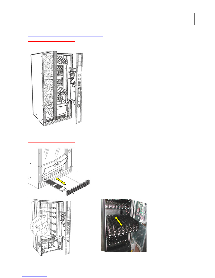
DAILY CLEANING AND HYGIENE
( Expected time 4 min.)
WEEKLY CLEANING AND HYGIENE
( Expected time 8 min.)
9 – PERIODIC CLEANING AND HYGIENE
In addition to the daily cleaning operations:
Remove the lower grille and slide out the pre-filter of the
cooling unit condenser (FIG. 1)
Clean and if necessary remove the dust with a vacuum
cleaner
(alternatively blow with compressed air in a different place
from the installation area).
Slide out the trays without removing them (FIG. 2-3) and
clean the inside of the cabinet with a cloth dampened with a
chlorine based detergent.
Check that there are no small insects.
Open the door and disconnect the machine form the
power supply (FIG 1).
Clean the outside and inside of the glass front with
suitable detergent.
Clean the inside of the trays with a cloth dampened
with chlorine-based detergents.
Wipe the dispensing compartment and the flap door
with a clean cloth
(These operations must be carried out before loading
the machine in the morning)
Dust all of the inside of the refrigerated box, especially
the base.
Enter the operation in the HACCP log.
When loading new products, check the expiry date of
the unsold ones and load the new products according
to the FIFO. (first in - first out) logic.
FIG. 1
FIG. 2
FIG. 3
FIG. 1
NECTA SPA TECHNICAL MANUAL
“
SFERA
“
Manual
“ SFERA”
19 /
19
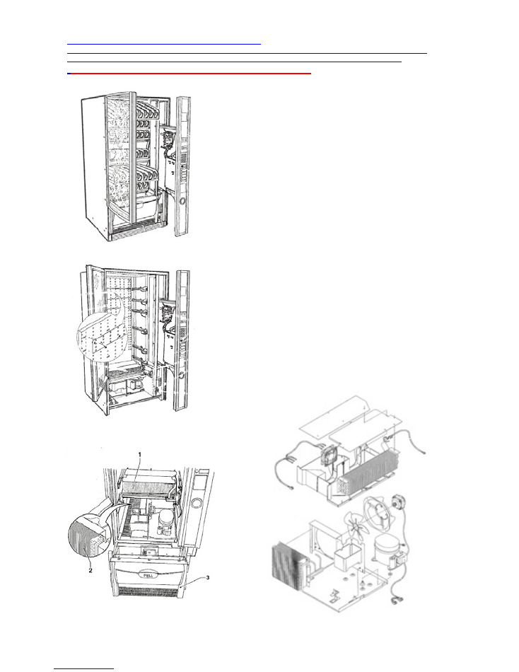
ANNUAL CLEANING AND HYGIENE
The “annual” period is intended as maximum term, as such maximum time must be reduced in accordance to the
specific situation and location of the vending machine to maintain its perfect state of hygiene at all times.
Expected time 20 min. (excluding the pull-down time “
* ”)
Open the door and disconnect the machine form the
power supply (FIG.1
Remove all trays, placing them in a clean area or in any
case protected by possible interference (FIG. 2)
Clean the inside of the refrigerated box with a damp
cloth soaked in chlorine-based detergents.
Completely remove the cooling unit
(FIG . 3) thoroughly clean the internal base and
make hygienic.
Remove all the dust from the fans and cooling unit
condenser (FIG. 4 ).
Clean and make hygienic the condensation tray (FIG.
4)
Reassemble the cooling unit proceeding in the reverse
order.
Reinsert into the operating position.
Clean the external parts, especially the coin-return
compartment and the push-buttons. Reassemble all
trays after cleaning the internal product loading parts.
Thoroughly clean the inside of the dispensing
compartment.
Start the machine and bring the internal temperature
to operating value.
Load all vending products.
*
Pull-Down: technical term that defines the length of time
required for bringing the temperature inside the cabinet to
the correct level
FIG. 1
FIG. 2
FIG. 3
FIG. 4