Full Text Searchable PDF User Manual
User Manual of MOBILUS C-MR external receiver
www.mobilus.pl
1. IMPORTANT INFORMATIONS
• When unpacking the unit, make sure that there is no damage in the transport. If so, you
should immediately inform the supplier.
• Read the operating manual carefully before use
• MOBILUS C-MR
module should be powered by 230 V ~, 50 Hz. Its installation should only
be carried out by persons with electrical qualifications according to the enclosed electrical
diagram in accordance with all applicable regulations.
• MOBILUS C-MR
module is designed to work with all
COSMO / COSMO | 2WAY
series remote controls.
• The range of the radio control is limited by regulations for maximum power of the remote
control and the conditions of the installation of the equipment. When designing the location
of the remote control, consider limiting the range to about 20m by 2 walls.
• Declaration of Conformity:
We declare under our sole responsibility that the
MOBILUS C-MR
complies with the
following European Directives:
1. 2014/53 / EU RED Radio Directive;
2. 2014/30 / EU Electromagnetic Compatibility Directive.
3. 73/23/EWG Low Voltage Directive.
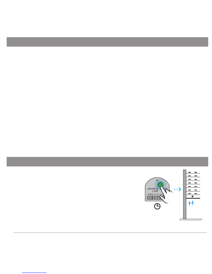
2. ENTRY INTO THE MODULE PROGRAMMING MODE
Press and hold a programming button on module
MOBILUS C-MR
above 5 sec until the connected actuator executes one sequence
of noticeable and audible micro movements down / up confirming
the entrence of the receiver in the PROGRAMMING MODE.
WARNING!
If within 20 seconds no programming will be per-
formed, the MOBILUS C-MR radio module automatically exits
from the programming mode. Connected actuator executes
one sequence of noticeable and audible micro movements
down / up, blinks are stopped.
1 s.
BEEP! BEEP!
PILOT 2
1 s.
b
5 s.
2
3. LOADING THE MASTER-A * CODE TO THE RECEIVER MEMORY
1. Enter the
MOBILUS C-MR
PROGRAMMING MODE.
2. Press and hold the
STOP
and
UP
buttons
simultaneously on the remote control until the connected
actuator executes one sequence of noticeable and audible
micro movements down / up.
3. The
MASTER
-a code has been loaded into memory and
the module goes to the WORK MODE. Now, with the
MASTER
remote control, you can operate the units or enter
the PROGRAM MODE to load more remote controls.
BEEP! BEEP!
PILOT 2
1 s.
b
5 s.
BEEP! BEEP!
WARNING
In the case of a multi-channel remote control
select only one channel to be
MASTER
.
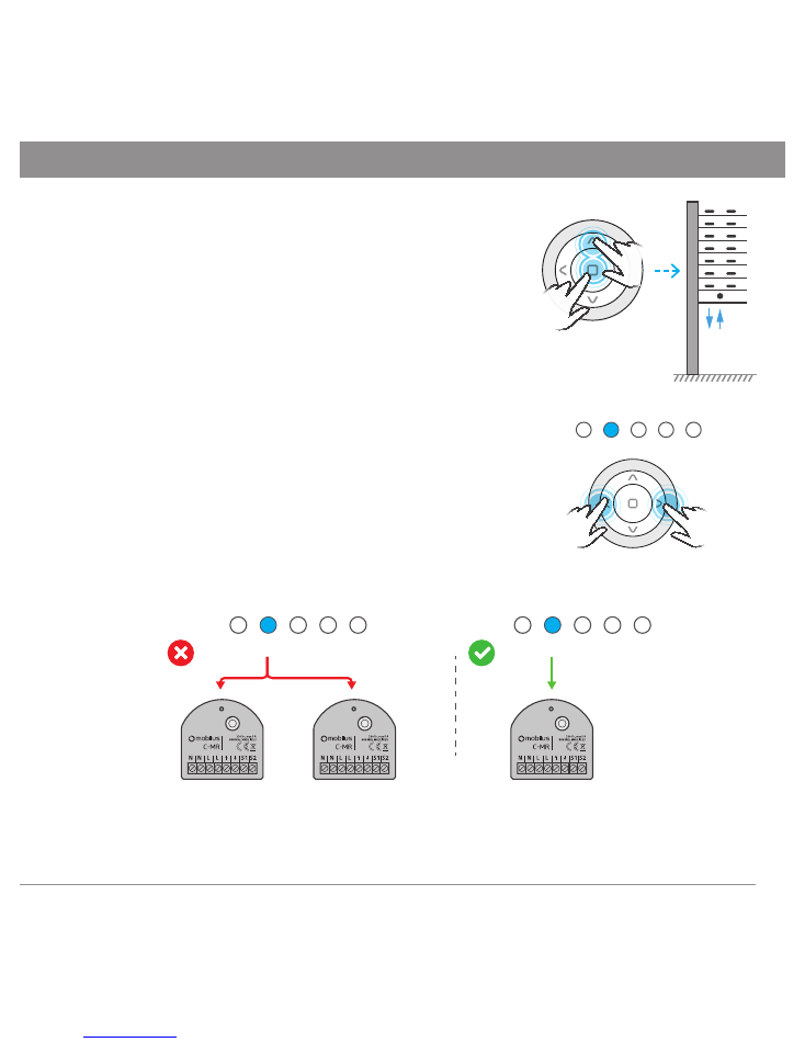
NOTE
For the convenience of programming, it is recom-
mended that each
COSMO | C-MR
module had its own
separate
MASTER
(remote control (separate channel for
multi-channel remotes).
Avoid situations where several
COSMO | C-MR modules remote controls will have
common MASTER (shared channel)
.
BEEP! BEEP!
MASTER
1
2
3
4
5
5 s.
BEEP! BEEP!
PILOT 2
1 s.
a
b
1
2
3
4
5
1
2
3
4
5
*MASTER
- remote control or channel (in the case of a multi-channel remotes) loaded first into
the memory of the
MOBILUS C-MR
module. Allows you to program further remote controls.
3
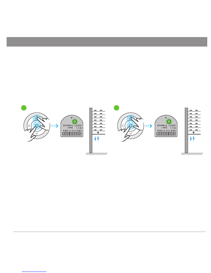
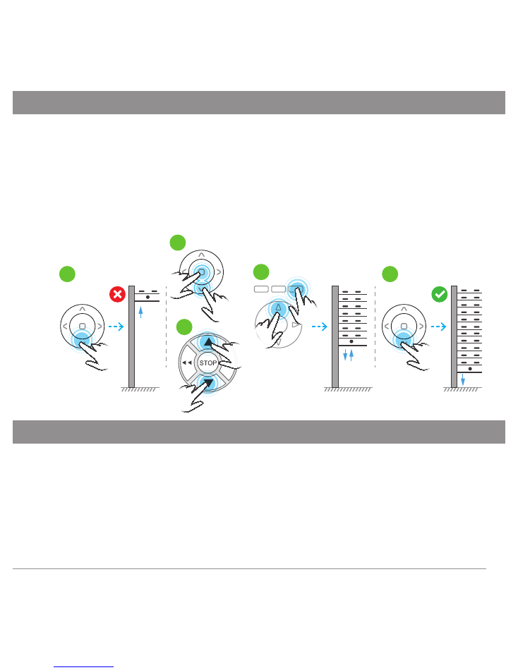
4. PROGRAMMING OF THE SECOND AND EVERY OTHER REMOTE CONTROL
1. On the
MASTER
remote control, simultaneously press and hold the
STOP
and
UP
until the
connected actuator executes one sequence of noticeable and audible micro movements down / up
confirming the entrence of the receiver in the PROGRAMMING MODE
- Fig. 4a
.
Additionally in this
mode every 1 sec. the diode is blinking.
2. On the second remote control (for the multi-channel remote control, select the channel
you want to program), press and hold both
STOP
and
UP
buttons simultaneously, until the
connected actuator performs one sequence of noticeable and audible micro movements
down / up. The remote (channel) was loaded into the receiver’s memory
- Fig. 4b
.
Fig. 4
MASTER
PILOT 2
a
b
Repeat step 2 to load the next remote control. If, however, no programming operation is started
within 20 seconds, the module automatically returns to operating mode. Return to operating
mode can also be performed manually using
MASTER
. In such a situation, press and hold the
STOP
and
UP MASTER
buttons. In both cases, the return to operating mode will be confirmed
by a single sequence of micro movements down / up of the connected actuator.
4
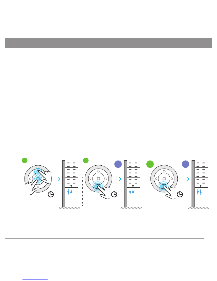
5. CHANGING THE DIRECTION OF THE ACTUATOR
1. If you press the
UP
button on the remote control and the armor goes down, change the
direction of rotation of the drive. At the same time, press and hold:
a ) on the remote control
COSMO | HM, | HB, | G3+, | WT9, | WT
buttons
STOP
and
DOWN
-
Fig. 5b
;
b ) on the remote control
COSMO | HT, | H24,| H1, | H5, | G, | W1, | W7
buttons
DOWN
and
UP
-
Fig. 5c
;
c ) on the remote control
COSMO | HCT
UP
and
F3
buttons
-
Fig. 5d
;
until the drive executes one sequence of micro down / up moves.
2. Check the
UP / DOWN
buttons
-
Fig. 5e
.
Fig. 5
a
e
b
c
d
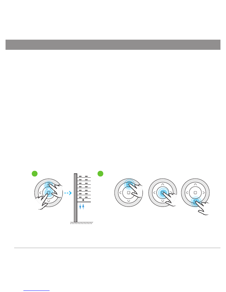
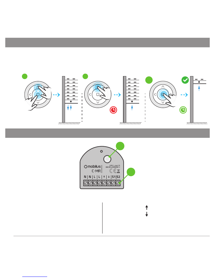
6. C-MR MODULE RESET - FACTORY SETTINGS
WARNING!!! RESTORATION OF FACTORY SETTINGS erases all programmed remotes from the
MOBILUS C-MR module.
1. Enter the PROGRAMMING MODE for the
MOBILUS C-MR
module -
Fig. 6a
.
2. In the PROGRAMMING MODE, press and hold the programming key above 5 seconds -
Fig.
6b
. All previously loaded remote modules have been removed from the memory module
which confirms one sequence of noticeable and audible micro moves down / up of the
connected actuator.
5
CONTINUED 6. C-MR MODULE RESET - FACTORY SETTINGS
Fig. 6
a
b
7. REMOVAL OF INDIVIDUAL REMOTES (CHANNELS)
It is possible to delete only one of the programmed remotes (not for MASTER remote). To do
this:
1. On the
MASTER
, press simultaneously and hold the
STOP
and
UP
buttons until the
connected actuator executes one sequence of noticeable and audible micro movements
down / up, confirming the receiver’s entrance into the programming mode
- Fig. 7a
.
Additionally in this mode every 1 sec. the diode is blinking.
2. On the remote control (channel) that you want to delete, press and hold the
STOP
and
UP
buttons simultaneously until the connected actuator performs one sequence of noticeable
and audible micro movements down / up, confirming the removal of the pilot code from the
actuator memory
- Fig. 7b
.
Fig. 7
MASTER
PILOT 2
a
b
6
CONTINUED 7. REMOVAL OF INDIVIDUAL REMOTES (CHANNELS)
WARNING!
Repeat step 2 to proceed to remove the next remote control. However, if within
20 sec. no programming operation is started, the receiver automatically returns to operating
mode. Return to operating mode can also be performed manually using the
MASTER
. In such
a situation, simultaneously press and hold the
STOP
and
MASTER
buttons until the connected
actuator executes one sequence of noticeable and audible micro movements down / up. In
both cases, the return to operating mode will be through one sequence of micro down / top
moves of the connected actuator.
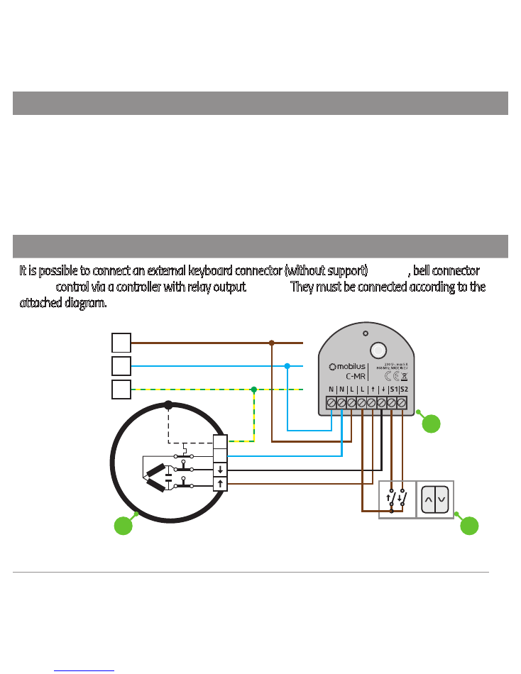
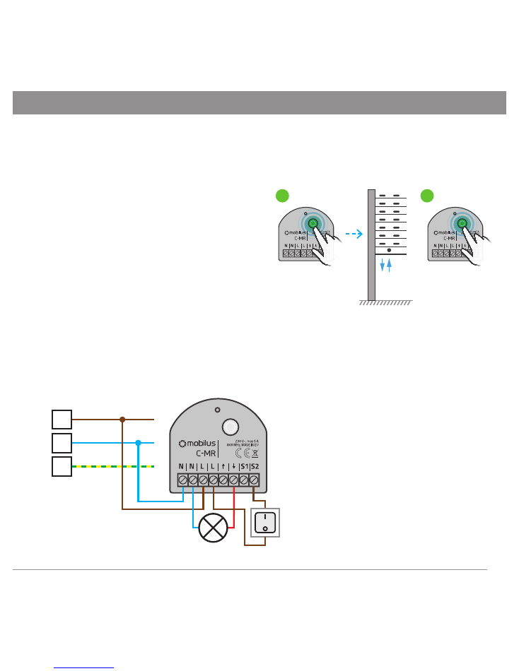
8. CONNECTING THE ADDITIONAL SWITCH / DRIVER
It is possible to connect an external keyboard connector (without support)
- Fig. 8.1
, bell connector
-
Fig. 8.2,
control via a controller with relay output
- Fig. 8.3.
They must be connected according to the
attached diagram.
Fig. 8.1
L1
N
PE
N
PE
230V~ 50Hz
a
b
L1
N
PE
N
PE
230V~ 50Hz
a
c
b
L1
N
PE
N
PE
230V~ 50Hz
a
b
L1
N
PE
N
PE
230V~ 50Hz
a
c
b
c
7
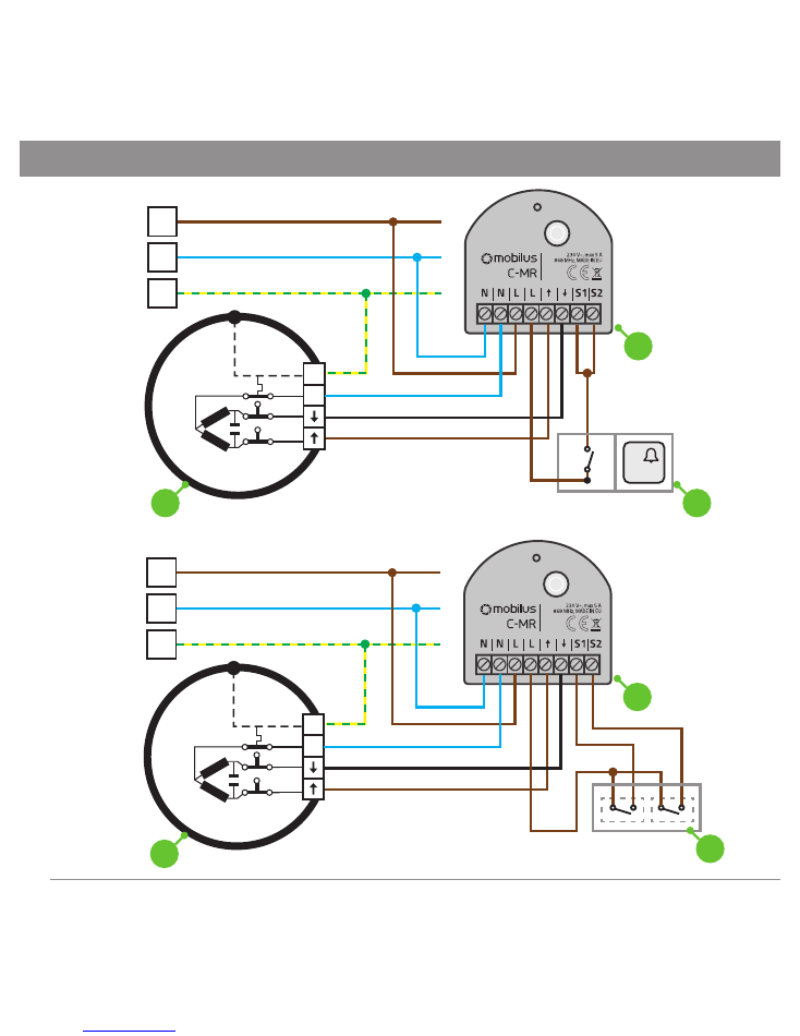
CONTINUED 8. CONNECTING THE ADDITIONAL SWITCH / DRIVER
Fig. 8.2
L1
N
PE
N
PE
230V~ 50Hz
a
b
L1
N
PE
N
PE
230V~ 50Hz
a
c
b
L1
N
PE
N
PE
230V~ 50Hz
a
b
L1
N
PE
N
PE
230V~ 50Hz
a
c
b
c
Fig. 8.3
L1
N
PE
N
PE
230V~ 50Hz
a
b
L1
N
PE
N
PE
230V~ 50Hz
a
c
b
L1
N
PE
N
PE
230V~ 50Hz
a
b
L1
N
PE
N
PE
230V~ 50Hz
a
c
b
c
8
9
9. CHANGING THE OPERATION MODE OF CONTROL BUTTONS
The MOBILUS
C-MR
module allows you to change the operating mode of the control buttons
I.
MODE WITH HOLD UP
- Pressing the key causes the roller shutter to be lowered or raised.
II.
MODE WITHOUT HOLD UP
- Lowering or raising the controlled roller shutter continues as
long as the control key is pressed.
To change the operation mode of the control buttons:
1. On the
MASTER
, press simultaneously and hold the
STOP
and
UP
buttons until the
connected actuator performs one sequence of noticeable and audible micro movements
down / up confirming the receiver entrance in the PROGRAMMING MODE
- Fig. 9a
.
Additionally in this mode every 1 sec. the diode is blinking.
2. On the
MASTER
, press the
DOWN
button and hold until the actuator connected to the
COSMO C-MR
module will perform two sequences of noticeable and audible micro
movements down / up. HOLD UP MODE is active
- Fig. 9b
.
3. To switch to MODE WITHOUT MAINTAIN, repeat step 1, then on the
MASTER
push
button
DOWN
and hold until connected to the module
COSMO C-MR
actuator performs a
sequence of visible and audible micro movements up / down
- Fig. 9c
.
Fig. 9
b
MASTER
a
2x
1x
c
I
II
10. REPEATER FUNCTION
SIGNAL REPEATER
- This feature allows you to expand the radio control area. The
MOBILUS C-MR
module with the repeater function enabled receives signals from the controller or actuators and
passes them forward. Thanks to the furthest located receivers which are not within the controller can
receive and transmit information through modules located indirectly. Turn on the repeater function:
1. Press the
STOP
and
UP
buttons simultaneously on the
MASTER
until the connected actuator executes
one sequence of noticeable and audible micro movements down / up, confirming entry into the
PROGRAMMING MODE. Additionally in this mode every 1 sec. the diode is blinking.
2. On the remote control, press the button sequence:
UP, STOP, DOWN, UP, STOP, DOWN
. Activation of
the repeater function will cause three sequences of
DOWN-UP
micro-movements by the actuator.
3. Repeat step 1 to deactivate the repeater function. Then press the button sequence:
UP, STOP,
DOWN, UP, STOP, DOWN
- confirmation of deactivation is the execution of two sequences of
micro-
DOWN-UP
movements by connected actuator.
WARNING!
Turn on the repeater function only on devices that are within range of the signal
range. Because of the efficient work, we recommend that you enable the signal repeater
function on up to three devices in the facility. Unreasonable inclusion of signal repeater on
many devices may cause interference in all radio equipment.
Fig. 10
b
MASTER
a
2X
10
11
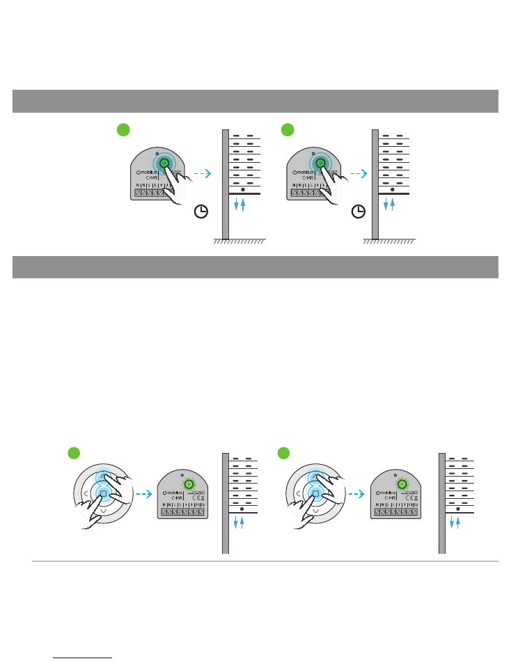
11. CONTINUOUS MODE - ON / OFF SWITCH
1. Press and hold the programming button on the
MOBILUS C-MR
receiver until the connected
actuator executes one sequence of noticeable and audible micro movements down / up confir-
ming the receiver’s entry into the programming mode (every 1 sec the LED flashes).
2. Press programming button in
COSMO C-MR
module three times,
at short intervals. The module will
confirm the change mode by multiple
beep sound and switching relays.
After changing the operating mode,
the module will exit from the PRO-
GRAMMING MODE. -
Fig.11.1b.
Fig. 11.1
b
x3
a
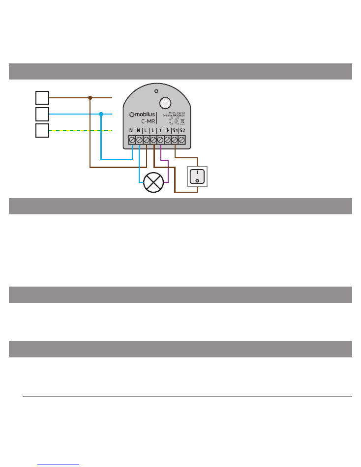
To deactivate CONTINUOUS MODE - repeat the procedure in steps 1 and 2.
IN THE CONTINUOUS MODE, the function of the button connected to terminal
S1 / S2
changes.
The button acts as a light switch - the switch under the terminal
S1
activates the relay in the
UP
direction, when the button is off, the relay turns
OFF
. Switched under the
S2
terminal works
analogically - in the
DOWN
direction.
Fig. 11.2
L1
N
PE
230V~ 50Hz
L1
N
PE
230V~ 50Hz
L1
N
PE
230V~ 50Hz
L1
N
PE
230V~ 50Hz
L1
N
PE
230V~ 50Hz
L1
N
PE
230V~ 50Hz
M
M
b
a
CONTINUOUS OPERATIONAL MODE
.
Illumination connected to inputs 2 and
6 - control with
DOWN
command.
CONTINUED 11. CONTINUOUS MODE - ON / OFF SWITCH
Fig. 11.3
L1
N
PE
230V~ 50Hz
L1
N
PE
230V~ 50Hz
L1
N
PE
230V~ 50Hz
L1
N
PE
230V~ 50Hz
L1
N
PE
230V~ 50Hz
L1
N
PE
230V~ 50Hz
M
M
b
a
CONTINUOUS OPERATIONAL
MODE
. Illumination connected
to inputs 2 and 5 - control with
DOWN
command.
12. BIDIRECTIONALITY
MOBILUS C-MR
with two-way communication with the remote control allows control of the
state of shutter position ( eg. open, closed, intermediate level, overload detection ).
Proper operation of bidirectional communication requires the use of pilots with bidirectional
communication.
Remote controls supporting two-way communication:
MOBILUS COSMO | HCT, COSMO | G3+,
COSMO | HM, COSMO | HB, COSMO | WT9, COSMO | WT.
13. BIDIRECTIONAL - INFORMATION ABOUT THE POSITION OF THE BLIND
MOBILUS C-MR
transmits information about the end position and intermediate position
blinds to remote controls. The mode is switched on automatically - there is no possibility of
deactivation.
14. BI-DIRECTIONAL - OVERLOAD INFORMATION
MOBILUS C-MR
transmits information to remotes about overload - for example, it may be
related to a housing lock occurring at the time of raising or lowering. Mode is factory-setted - it
is possible to turn off.
12
13
CONTINUED 14. BI-DIRECTIONAL - OVERLOAD INFORMATION
Enable / disable of overload detection:
1. At the
MASTER
remote control press and hold the
STOP
and
UP
buttons simultaneously
until the connected actuator performs one sequence of noticeable and audible micro
movements down / up confirming the receiver input into the programming mode
- Fig. 14a
.
Additionally in this mode every 1 sec. the diode is blinking.
2. On the
MASTER
, press the
STOP
button and hold until the actuator connected to the
MOBILUS C-MR
module will perform two sequences of noticeable and audible micro
movements down / up. Overload detection active
- Fig. 14b
.
3. To stop the overload detection, repeat step 1. Then press the
STOP
button on the
MASTER
control and hold until the actuator connected to the
MOBILUS C-MR
module will perform 1
sequence of noticeable and audible micro moves down / up
- Fig. 14c
.
Fig. 14
b
MASTER
a
2x
c
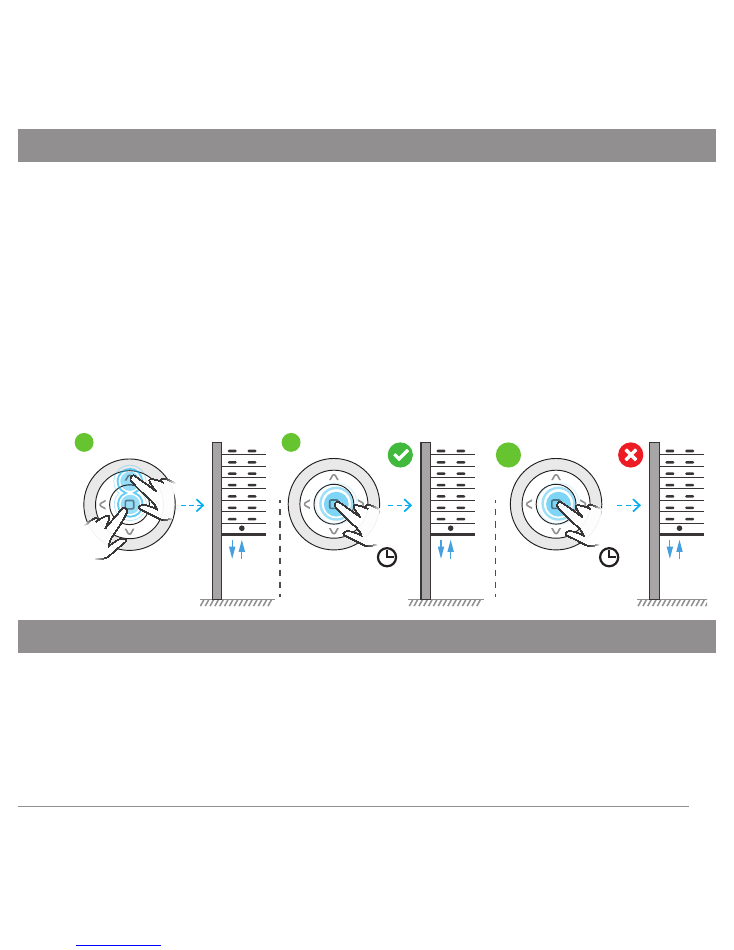
15. SETTING OF THE SWITCHING TIME OF RELAYS
MOBILUS C-MR
allows you to change the relay switching time. This operation is necessary, for
example, for very high shutters. By default this time is 120 seconds.
1. Press
MASTER
at the same time and hold the
STOP
and
UP
buttons until the connected
actuator performs one sequence of noticeable and audible micro movements down / up,
confirming the receiver entry into the programming mode
- Fig. 15a
.
Additionally in this mode
every 1 sec. the LED flashes.
CONTINUED 15. SETTING OF THE SWITCHING TIME OF RELAYS
2. On the
MASTER
, press the
UP
button
- Fig. 15b
.
The blind will begin to rise.
3. At the moment when the user presses the
STOP
key, the new relay operating time is
saved
- Fig. 15c
.
Fig.15
b
MASTER
a
c
16. PRODUCT DESCRIPTION
L1
N
PE
230V~ 50Hz
L1
N
PE
230V~ 50Hz
L1
N
PE
230V~ 50Hz
L1
N
PE
230V~ 50Hz
L1
N
PE
230V~ 50Hz
L1
N
PE
230V~ 50Hz
M
M
b
a
a) Programming button;
b) Connection terminals;
N
- neutral;
N
- neutral;
L
- phase
;
L
- phase;
- UP;
- DOWN;
S1
- switch up;
S2
- switch down;
14
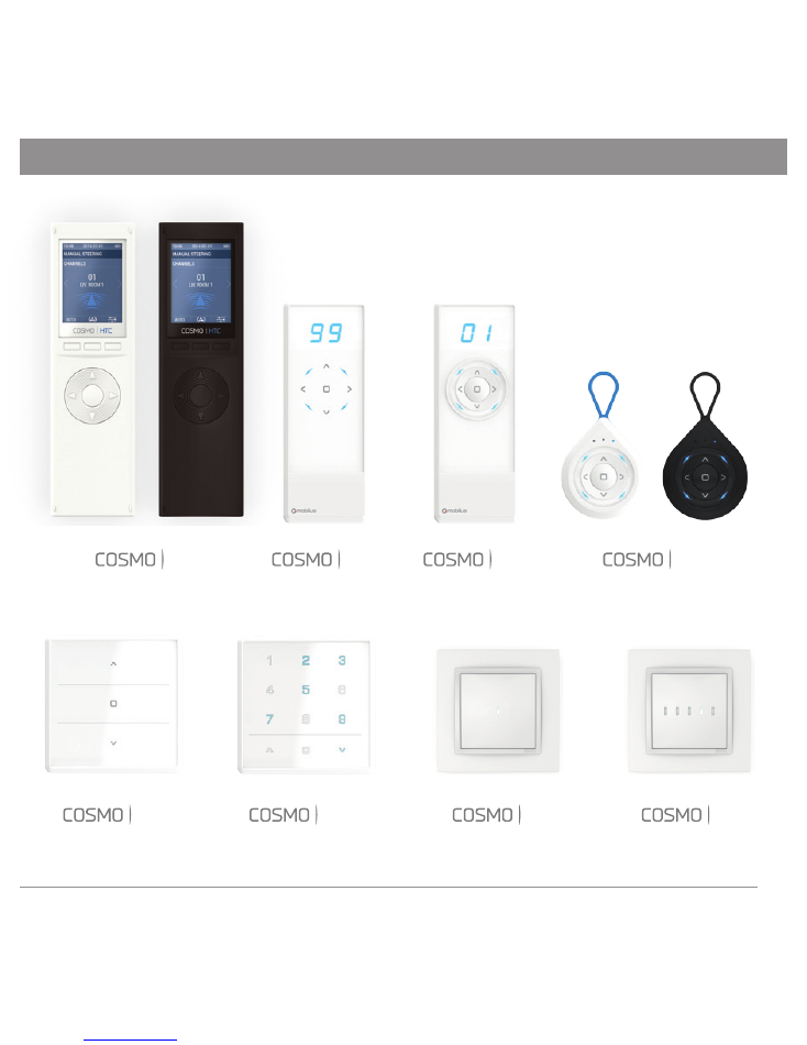
HCT
HB
HM
G3+
15
17. CONTROL REMOTES - „COSMO” SERIES
WT
WT9
L1
L5

MOBILUS MOTOR Spółka z o.o.
ul. Miętowa 37, 61-680 Poznań, PL
tel. +48 61 825 81 11, fax +48 61 825 80 52
VAT NO. PL9721078008
www.mobilus.pl
Wersja 1.0ENG, 161124