Full Text Searchable PDF User Manual

Multi V Air Conditioner
SVC MANUAL(Exploded View)
MODEL :
CAUTION
Before Servicing the unit, read the safety precautions in General SVC manual.
Only for authorized service personnel.
CONFIDENTIAL
Any reproduction, duplication, distribution (including by way of email, facsimile or other electronic means), publication,
modification, copying or transmission of this Service Manual is STRICTLY PROHIBITED unless you have obtained
the prior written consent of the LG Electronics entity from which you received this Service Manual. The material
covered by this prohibition includes, without limitation, any text, graphics or logos in this Service Manual.
Copyright © 2018 LG Electronics Inc. All rights reserved. Only training and service purposes.
ARNU073M2A4
ARNU093M2A4
ARNU123M2A4
ARNU153M2A4
ARNU183M2A4
ARNU243M2A4
ARNU283M2A4
ARNU363M2A4
ARNU423M2A4
ARNU283M3A4
ARNU363M3A4
ARNU423M3A4
ARNU483M3A4
ARNU543M3A4

- 2 -
Copyright © 2018 LG Electronics Inc.
All rights reserved. Only training and service purposes.
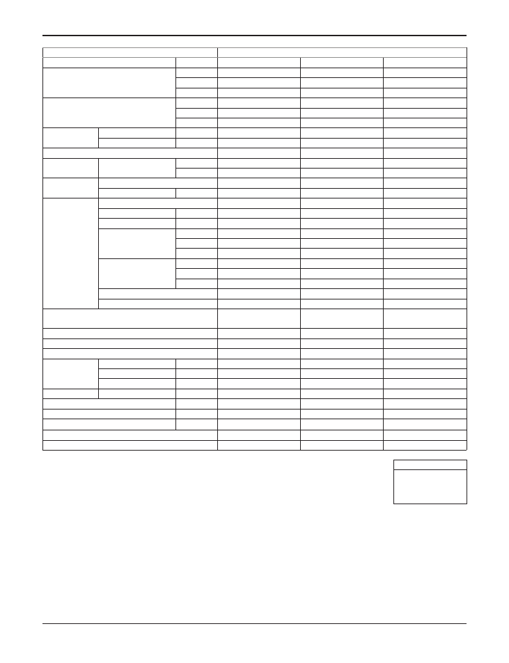
1. Specification
Type
Ceiling Concealed Duct -Middle Static
Model
Unit
ARNU073M2A4 ARNU093M2A4 ARNU123M2A4
Cooling Capacity
kW
kcal/h
Btu/h
Heating Capacity
kW
kcal/h
Btu/h
Power Input
Nominal W
Rated W
Casing
Dimensions
(WxHxD)
Body
mm
inch
Coil
Rows x Columns x FPI
Face Area
m
2
(ft
2
)
Fan
Type
Motor Output x Number
W
Running Current
A
Air Flow Rate(H / M / L)
(High Mode-Factory Set)
External static pressure
CMM
CFM
mmAq(Pa)
Air Flow Rate(H / M / L)
(Standard mode)
External static Pressure
CMM
CFM
mmAq(Pa)
Drive
Motor type
Temperature Control
Sound Absorbing Thermal Insulation Material
Air Filter
Safety Device
Pipe Connections
Liquid Side
mm(inch)
Gas Side
mm(inch)
Drain Pipe(Internal Dia.)
mm(inch)
Net Weight
Body
kg(lbs)
Sound Pressure Levels (H / M / L)
dB(A)
Sound Power Levels (H / M / L)
dB(A)
Power Supply
Ø, V, Hz
Refrigerant Control
Transmission Cable (AWG# -C)
2.2
1 900
7 500
2.5
2 200
8 500
32
430
Galvanized Steel Plate
1 250 × 270 × 700
49-7/32 x 10-5/8 x 27-9/16
2 x 13 x 18
0.27(2.91)
Sirocco Fan
350 x 1
2.3
13.3 / 9.4 / 6.8
470 / 332 / 240
6(59)
13.3 / 9.4 / 6.8
470 / 332 / 240
5(49)
Direct
BLDC
Microprocessor, Thermostat
for cooling and heating
Foamed polystrene
-
Fuse
Ø6.35(1/4)
Ø12.7(1/2)
25(1)
37.6(83)
38 / 37 / 36
53 / 52 / 52
1, 208-230, 60
EEV
AWG 18 x 2C
2.8
2 400
9 600
3.2
2 800
10 900
32
430
Galvanized Steel Plate
1 250 × 270 × 700
49-7/32 x 10-5/8 x 27-9/16
2 x 13 x 18
0.27(2.91)
Sirocco Fan
350 x 1
2.3
13.3 / 9.4 / 6.8
470 / 332 / 240
6(59)
13.3 / 9.4 / 6.8
470 / 332 / 240
5(49)
Direct
BLDC
Microprocessor, Thermostat
for cooling and heating
Foamed polystrene
-
Fuse
Ø6.35(1/4)
Ø12.7(1/2)
25(1)
37.6(83)
38 / 37 / 36
53 / 52 / 52
1, 208-230, 60
EEV
AWG 18 x 2C
3.6
3 100
12 300
4
3 400
13 600
33
430
Galvanized Steel Plate
1 250 × 270 × 700
49-7/32 x 10-5/8 x 27-9/16
2 x 13 x 18
0.27(2.91)
Sirocco Fan
350 x 1
2.3
14.8 / 10.2 / 7.4
523 / 360 / 261
6(59)
14.8 / 10.2 / 7.4
523 / 360 / 261
5(49)
Direct
BLDC
Microprocessor, Thermostat
for cooling and heating
Foamed polystrene
-
Fuse
Ø6.35(1/4)
Ø12.7(1/2)
25(1)
37.6(83)
38 / 37 / 36
54 / 53 / 53
1, 208-230, 60
EEV
AWG 18 x 2C
Notes:-
1. Capacities are based on the following conditions:
Cooling • Indoor temp. 27°C[80.6°F]DB/ 19°C[66.2°F]WB
• Outdoor temp. 35°C[95°F]DB/ 24°C[75.2°F]WB
• Interconnecting Piping Length 7.5m(24.6ft)
• Level Difference of Zero
Heating • Indoor temp. 20°C[68°F]DB/ 15°C[59°F]WB
• Outdoor temp. 7°C[44.6°F]DB/ 6°C[42.8°F]WB
• Interconnecting Piping Length 7.5m(24.6ft)
• Level Difference of Zero
2. Capacities are net capacities
3. Due to our policy of innovation some specifications may be changed without prior notification
4. To be added for more available Models
5. EEV : Electronic Expansion Valve
6. Noise Level is Standard Mode
(for actual High Mode(factory set) condition, Noise Level may exceed the standard level by 1.5dBA)
Conversion Formula
kcal/h= kW x 860
Btu/h = kW x 3 412
CFM = m
3
/min x 35.3
l/s = CMM x 1 000/60

- 3 -
Copyright © 2018 LG Electronics Inc.
All rights reserved. Only training and service purposes.
Notes:-
1. Capacities are based on the following conditions:
Cooling • Indoor temp. 27°C[80.6°F]DB/ 19°C[66.2°F]WB
• Outdoor temp. 35°C[95°F]DB/ 24°C[75.2°F]WB
• Interconnecting Piping Length 7.5m(24.6ft)
• Level Difference of Zero
Heating • Indoor temp. 20°C[68°F]DB/ 15°C[59°F]WB
• Outdoor temp. 7°C[44.6°F]DB/ 6°C[42.8°F]WB
• Interconnecting Piping Length 7.5m(24.6ft)
• Level Difference of Zero
2. Capacities are net capacities
3. Due to our policy of innovation some specifications may be changed without prior notification
4. To be added for more available Models
5. EEV : Electronic Expansion Valve
6. Noise Level is Standard Mode
(for actual High Mode(factory set) condition, Noise Level may exceed the standard level by 1.5dBA)
Conversion Formula
kcal/h= kW x 860
Btu/h = kW x 3 412
CFM = m
3
/min x 35.3
l/s = CMM x 1 000/60
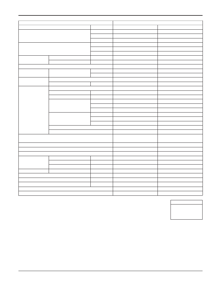
Type
Ceiling Concealed Duct -Middle Static
Model
Unit
ARNU153M2A4
ARNU183M2A4 ARNU243M2A4
Cooling Capacity
kW
kcal/h
Btu/h
Heating Capacity
kW
kcal/h
Btu/h
Power Input
Nominal W
Rated W
Casing
Dimensions
(WxHxD)
Body
mm
inch
Coil
Rows x Columns x FPI
Face Area
m
2
(ft
2
)
Fan
Type
Motor Output x Number
W
Running Current
A
Air Flow Rate(H / M / L)
(High Mode-Factory Set)
External static pressure
CMM
CFM
mmAq(Pa)
Air Flow Rate(H / M / L)
(Standard mode)
External static Pressure
CMM
CFM
mmAq(Pa)
Drive
Motor type
Temperature Control
Sound Absorbing Thermal Insulation Material
Air Filter
Safety Device
Pipe Connections
Liquid Side
mm(inch)
Gas Side
mm(inch)
Drain Pipe(Internal Dia.)
mm(inch)
Net Weight
Body
kg(lbs)
Sound Pressure Levels (H / M / L)
dB(A)
Sound Power Levels (H / M / L)
dB(A)
Power Supply
Ø, V, Hz
Refrigerant Control
Transmission Cable (AWG# -C)
4.5
3 900
15 400
5
4 300
17 100
33
430
Galvanized Steel Plate
1 250 × 270 × 700
49-7/32 x 10-5/8 x 27-9/16
2 x 13 x 18
0.27(2.91)
Sirocco Fan
350 x 1
2.3
14.8 / 10.2 / 7.4
523 / 360 / 261
6(59)
14.8 / 10.2 / 7.4
523 / 360 / 261
5(49)
Direct
BLDC
Microprocessor, Thermostat
for cooling and heating
Foamed polystrene
-
Fuse
Ø6.35(1/4)
Ø12.7(1/2)
25(1)
37.6(83)
38 / 37 / 36
53 / 53 / 52
1, 208-230, 60
EEV
AWG 18 x 2C
5.6
4 800
19 100
6.3
5 400
21 500
50
430
Galvanized Steel Plate
1 250 × 270 × 700
49-7/32 x 10-5/8 x 27-9/16
2 x 13 x 18
0.27(2.91)
Sirocco Fan
350 x 1
2.3
18.5 / 14.8 / 10.2
653 / 523 / 360
6(59)
18.5 / 14.8 / 10.2
653 / 523 / 360
5(49)
Direct
BLDC
Microprocessor, Thermostat
for cooling and heating
Foamed polystrene
-
Fuse
Ø6.35(1/4)
Ø12.7(1/2)
25(1)
37.6(83)
39 / 38 / 37
54 / 53 / 53
1, 208-230, 60
EEV
AWG 18 x 2C
7.1
6 100
24 200
8
6 900
27 300
50
430
Galvanized Steel Plate
1 250 × 270 × 700
49-7/32 x 10-5/8 x 27-9/16
2 x 13 x 18
0.27(2.91)
Sirocco Fan
350 x 1
2.3
18.5 / 14.8 / 10.2
653 / 523 / 360
6(59)
18.5 / 14.8 / 10.2
653 / 523 / 360
5(49)
Direct
BLDC
Microprocessor, Thermostat
for cooling and heating
Foamed polystrene
-
Fuse
Ø9.52(3/8)
Ø15.88(5/8)
25(1)
37.6(83)
39 / 38 / 37
54 / 53 / 53
1, 208-230, 60
EEV
AWG 18 x 2C
Type
Ceiling Concealed Duct -Middle Static
Model
Unit
ARNU283M2A4 ARNU363M2A4 ARNU423M2A4
Cooling Capacity
kW
kcal/h
Btu/h
Heating Capacity
kW
kcal/h
Btu/h
Power Input
Nominal W
Rated W
Casing
Dimensions
(WxHxD)
Body
mm
inch
Coil
Rows x Columns x FPI
Face Area
m
2
(ft
2
)
Fan
Type
Motor Output x Number
W
Running Current
A
Air Flow Rate(H / M / L)
(High Mode-Factory Set)
External static pressure
CMM
CFM
mmAq(Pa)
Air Flow Rate(H / M / L)
(Standard mode)
External static Pressure
CMM
CFM
mmAq(Pa)
Drive
Motor type
Temperature Control
Sound Absorbing Thermal Insulation Material
Air Filter
Safety Device
Pipe Connections
Liquid Side
mm(inch)
Gas Side
mm(inch)
Drain Pipe(Internal Dia.)
mm(inch)
Net Weight
Body
kg(lbs)
Sound Pressure Levels (H / M / L)
dB(A)
Sound Power Levels (H / M / L)
dB(A)
Power Supply
Ø, V, Hz
Refrigerant Control
Transmission Cable (AWG# -C)
- 4 -
Copyright © 2018 LG Electronics Inc.
All rights reserved. Only training and service purposes.
8.2
7 100
28 000
9.2
8 000
31 500
123
430
Galvanized Steel Plate
1 250 × 270 × 700
49-7/32 x 10-5/8 x 27-9/16
3 x 13 x 18
0.27(2.91)
Sirocco Fan
350 x 1
2.3
28.0 / 24.0 / 21.0
989 /848 / 742
6(59)
28.0 / 24.0 / 21.0
989 /848 / 742
5(49)
Direct
BLDC
Microprocessor, Thermostat
for cooling and heating
Foamed polystrene
-
Fuse
Ø9.52(3/8)
Ø15.88(5/8)
25(1)
39.1(86)
40 / 39 / 37
64 / 61 / 57
1, 208-230, 60
EEV
AWG 18 x 2C
10.6
9 100
36 200
11.9
10 200
40 600
184
430
Galvanized Steel Plate
1 250 × 270 × 700
49-7/32 x 10-5/8 x 27-9/16
3 x 13 x 18
0.27(2.91)
Sirocco Fan
350 x 1
2.3
28.0 / 24.0 / 21.0
989 / 848 / 742
6(59)
28.0 / 24.0 / 21.0
989 / 848 / 742
5(49)
Direct
BLDC
Microprocessor, Thermostat
for cooling and heating
Foamed polystrene
-
Fuse
Ø9.52(3/8)
Ø15.88(5/8)
25(1)
39.1(86)
42 / 40 / 38
65 / 62 / 60
1, 208-230, 60
EEV
AWG 18 x 2C
12.3
10 600
42 000
13.8
11 800
47 000
231
430
Galvanized Steel Plate
1 250 × 270 × 700
49-7/32 x 10-5/8 x 27-9/16
3 x 13 x 18
0.27(2.91)
Sirocco Fan
350 x 1
2.3
38.0 / 33.0 / 28.0
1 342 / 1 165 / 989
6(59)
38.0 / 33.0 / 28.0
1 342 / 1 165 / 989
5(49)
Direct
BLDC
Microprocessor, Thermostat
for cooling and heating
Foamed polystrene
-
Fuse
Ø9.52(3/8)
Ø15.88(5/8)
25(1)
39.1(86)
44 / 43 / 40
66 / 65 / 63
1, 208-230, 60
EEV
AWG 18 x 2C
Notes:-
1. Capacities are based on the following conditions:
Cooling • Indoor temp. 27°C[80.6°F]DB/ 19°C[66.2°F]WB
• Outdoor temp. 35°C[95°F]DB/ 24°C[75.2°F]WB
• Interconnecting Piping Length 7.5m(24.6ft)
• Level Difference of Zero
Heating • Indoor temp. 20°C[68°F]DB/ 15°C[59°F]WB
• Outdoor temp. 7°C[44.6°F]DB/ 6°C[42.8°F]WB
• Interconnecting Piping Length 7.5m(24.6ft)
• Level Difference of Zero
2. Capacities are net capacities
3. Due to our policy of innovation some specifications may be changed without prior notification
4. To be added for more available Models
5. EEV : Electronic Expansion Valve
6. Noise Level is Standard Mode
(for actual High Mode(factory set) condition, Noise Level may exceed the standard level by 1.5dBA)
Conversion Formula
kcal/h= kW x 860
Btu/h = kW x 3412
CFM = m
3
/min x 35.3
l/s = CMM x 1 000/60

Type
Ceiling Concealed Duct -Middle Static
Model
Unit
ARNU283M3A4 ARNU363M3A4 ARNU423M3A4
Cooling Capacity
kW
kcal/h
Btu/h
Heating Capacity
kW
kcal/h
Btu/h
Power Input
Nominal W
Rated W
Casing
Dimensions
(WxHxD)
Body
mm
inch
Coil
Rows x Columns x FPI
Face Area
m
2
(ft
2
)
Fan
Type
Motor Output x Number
W
Running Current
A
Air Flow Rate(H / M / L)
(High Mode-Factory Set)
External static pressure
CMM
CFM
mmAq(Pa)
Air Flow Rate(H / M / L)
(Standard mode)
External static Pressure
CMM
CFM
mmAq(Pa)
Drive
Motor type
Temperature Control
Sound Absorbing Thermal Insulation Material
Air Filter
Safety Device
Pipe Connections
Liquid Side
mm(inch)
Gas Side
mm(inch)
Drain Pipe(Internal Dia.)
mm(inch)
Net Weight
Body
kg(lbs)
Sound Pressure Levels (H / M / L)
dB(A)
Sound Power Levels (H / M / L)
dB(A)
Power Supply
Ø, V, Hz
Refrigerant Control
Transmission Cable (AWG# -C)
- 5 -
Copyright © 2018 LG Electronics Inc.
All rights reserved. Only training and service purposes.
8.2
7 100
28 000
9.2
8 000
31 500
97
650
Galvanized Steel Plate
1 250 × 360 × 700
49-7/32 x 14-3/16 x 27-9/16
3 x 16 x 18
0.32(3.44)
Sirocco Fan
500 x 1
2.5
35.5 / 30.6 / 26.2
1 254 / 1 081 / 925
6(59)
35.5 / 30.6 / 26.2
1 254 / 1 081 / 925
5(49)
Direct
BLDC
Microprocessor, Thermostat
for cooling and heating
Foamed polystyrene
-
Fuse
Ø9.52(3/8)
Ø15.88(5/8)
25(1)
43.6(96)
40 / 39 / 37
64 / 62 / 61
1, 208-230, 60
EEV
AWG 18 x 2C
10.6
9 100
36 200
11.9
10 200
40 600
109
650
Galvanized Steel Plate
1 250 × 360 × 700
49-7/32 x 14-3/16 x 27-9/16
3 x 16 x 18
0.32(3.44)
Sirocco Fan
500 x 1
2.5
38.4 / 33.1 / 26.7
1 357 / 1 170 / 943
6(59)
38.4 / 33.1 / 26.7
1 357 / 1 170 / 943
5(49)
Direct
BLDC
Microprocessor, Thermostat
for cooling and heating
Foamed polystyrene
-
Fuse
Ø9.52(3/8)
Ø15.88(5/8)
25(1)
43.6(96)
41 / 39 / 37
65 / 63 / 61
1, 208-230, 60
EEV
AWG 18 x 2C
12.3
10 600
42 000
13.8
11 800
47 000
109
650
Galvanized Steel Plate
1 250 × 360 × 700
49-7/32 x 14-3/16 x 27-9/16
3 x 16 x 18
0.32(3.44)
Sirocco Fan
500 x 1
2.5
38.4 / 33.1 / 26.7
1 357 / 1 170 / 943
6(59)
38.4 / 33.1 / 26.7
1 357 / 1 170 / 943
5(49)
Direct
BLDC
Microprocessor, Thermostat
for cooling and heating
Foamed polystyrene
-
Fuse
Ø9.52(3/8)
Ø15.88(5/8)
25(1)
43.6(96)
41 / 39 / 37
65 / 63 / 61
1, 208-230, 60
EEV
AWG 18 x 2C
Notes:-
1. Capacities are based on the following conditions:
Cooling • Indoor temp. 27°C[80.6°F]DB/ 19°C[66.2°F]WB
• Outdoor temp. 35°C[95°F]DB/ 24°C[75.2°F]WB
• Interconnecting Piping Length 7.5m(24.6ft)
• Level Difference of Zero
Heating • Indoor temp. 20°C[68°F]DB/ 15°C[59°F]WB
• Outdoor temp. 7°C[44.6°F]DB/ 6°C[42.8°F]WB
• Interconnecting Piping Length 7.5m(24.6ft)
• Level Difference of Zero
2. Capacities are net capacities
3. Due to our policy of innovation some specifications may be changed without prior notification
4. To be added for more available Models
5. EEV : Electronic Expansion Valve
6. Noise Level is Standard Mode
(for actual High Mode(factory set) condition, Noise Level may exceed the standard level by 1.5dBA)
Conversion Formula
kcal/h= kW x 860
Btu/h = kW x 3412
CFM = m
3
/min x 35.3
l/s = CMM x 1 000/60
- 6 -
Copyright © 2018 LG Electronics Inc.
All rights reserved. Only training and service purposes.
Type
Ceiling Concealed Duct -Middle Static
Model
Unit
ARNU483M3A4 ARNU543M3A4
Cooling Capacity
kW
kcal/h
Btu/h
Heating Capacity
kW
kcal/h
Btu/h
Power Input
Nominal W
Rated W
Casing
Dimensions (WxHxD)
Body
mm
inch
Coil
Rows x Columns x FPI
Face Area
m
2
(ft
2
)
Fan
Type
Motor Output x Number
W
Running Current
A
Air Flow Rate(H / M / L)
(High Mode-Factory Set)
External static pressure
CMM
CFM
mmAq(Pa)
Air Flow Rate(H / M / L)
(Standard mode)
External static Pressure
CMM
CFM
mmAq(Pa)
Drive
Motor type
Temperature Control
Sound Absorbing Thermal Insulation Material
Air Filter
Safety Device
Pipe Connections
Liquid Side
mm(inch)
Gas Side
mm(inch)
Drain Pipe(Internal Dia.)
mm(inch)
Net Weight
Body
kg(lbs)
Sound Pressure Levels (H / M / L)
dB(A)
Sound Power Levels (H / M / L)
dB(A)
Power Supply
Ø, V, Hz
Refrigerant Control
Transmission Cable (AWG# -C)
14.1
12 100
48 100
15.9
13 600
54 200
172
650
Galvanized Steel Plate
1 250 × 360 × 700
49-7/32 x 14-3/16 x 27-9/16
3 x 16 x 18
0.32(3.44)
Sirocco Fan
500 x 1
2.5
40.0 / 34.0 / 28.0
1 413 / 1 201 / 989
6(59)
40.0 / 34.0 / 28.0
1 413 / 1 201 / 989
5(49)
Direct
BLDC
Microprocessor, Thermostat for
cooling and heating
Foamed polystyrene
-
Fuse
Ø9.52(3/8)
Ø15.88(5/8)
25(1)
43.6(96)
42 / 39 / 37
67 / 64 / 62
1, 208-230, 60
EEV
AWG 18 x 2C
15.8
13 600
54 000
18
15 500
61 400
260
650
Galvanized Steel Plate
1 250 × 360 × 700
49-7/32 x 14-3/16 x 27-9/16
3 x 16 x 18
0.32(3.44)
Sirocco Fan
500 x 1
2.5
50.0 / 45.0 / 40.0
1 766 / 1 589 / 1 413
6(59)
50.0 / 45.0 / 40.0
1 766 / 1 589 / 1 413
5(49)
Direct
BLDC
Microprocessor, Thermostat for
cooling and heating
Foamed polystyrene
-
Fuse
Ø9.52(3/8)
Ø15.88(5/8)
25(1)
43.6(96)
44 / 43 / 42
69 / 68 / 67
1, 208-230, 60
EEV
AWG 18 x 2C
Notes:-
1. Capacities are based on the following conditions:
Cooling • Indoor temp. 27°C[80.6°F]DB/ 19°C[66.2°F]WB
• Outdoor temp. 35°C[95°F]DB/ 24°C[75.2°F]WB
• Interconnecting Piping Length 7.5m(24.6ft)
• Level Difference of Zero
Heating • Indoor temp. 20°C[68°F]DB/ 15°C[59°F]WB
• Outdoor temp. 7°C[44.6°F]DB/ 6°C[42.8°F]WB
• Interconnecting Piping Length 7.5m(24.6ft)
• Level Difference of Zero
2. Capacities are net capacities
3. Due to our policy of innovation some specifications may be changed without prior notification
4. To be added for more available Models
5. EEV : Electronic Expansion Valve
6. Noise Level is Standard Mode
(for actual High Mode(factory set) condition, Noise Level may exceed the standard level by 1.5dBA)
Conversion Formula
kcal/h= kW x 860
Btu/h = kW x 3412
CFM = m
3
/min x 35.3
l/s = CMM x 1 000/60
- 7 -
Copyright © 2018 LG Electronics Inc.
All rights reserved. Only training and service purposes.
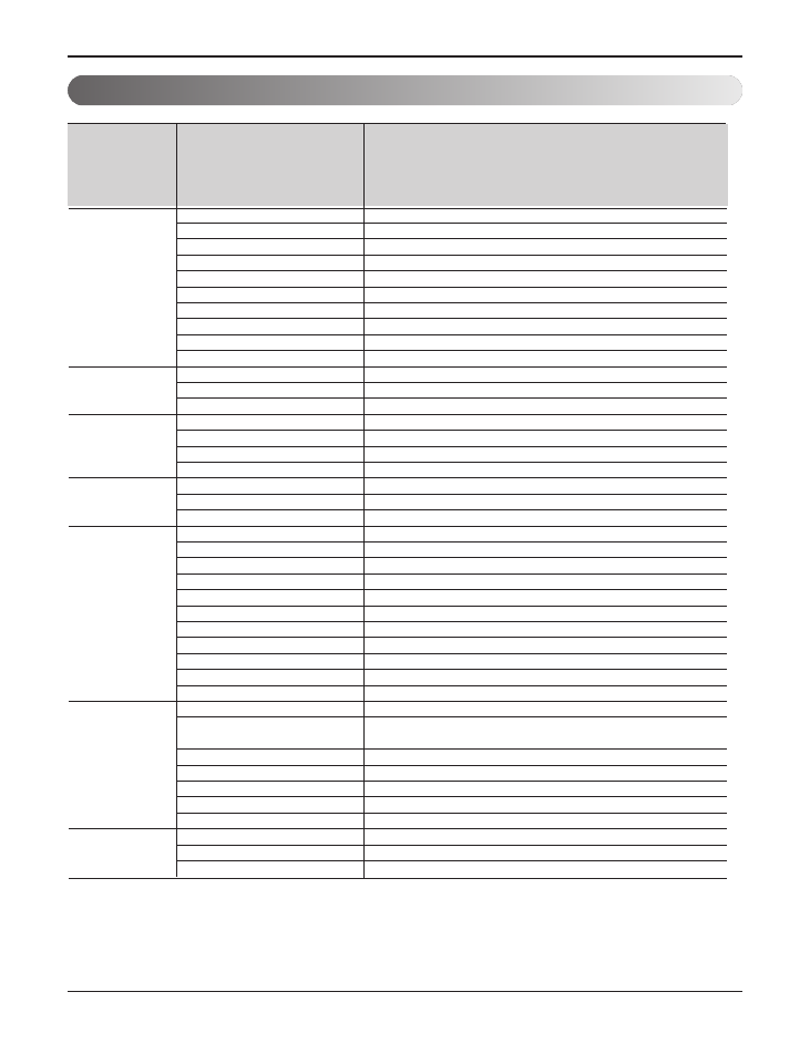
2. List of Functions
Air supply outlet
Airflow direction control(left & right)
Airflow direction control(up & down)
Auto swing(left & right)
Air flow
Auto swing(up & down)
Airflow steps(fan/cool/heat)
Chaos swing
Chaos wind(auto wind)
Jet cool(Power wind)
Swirl wind
Deodorizing filter
Air purifying Plasma air purifier
Prefilter(washable / anti-fungus)
Drain pump
Installation
E.S.P. control
Electric heater(operation)
High ceiling operation
Hot start
Reliability Self diagnosis
Soft dry operation
Auto changeover
Auto cleaning
Auto operation(artificial intelligence)
Auto restart operation
Child lock
Convenience Forced operation
Group control
Sleep mode
Timer(on/off)
Timer(weekly)
Two thermistor control
Standard wired remote controller
Wide Character wired remote controller
Picto wired remote controller
Individual Deluxe wired remote controller
control Simple wired remote controller
Wired remote controller(for hotel use)
Wireless remote controller(simple)
Wireless LCD remote control
Special
Zone control
function kit
CTIE
Electro thermostat
1
-
-
-
-
3/3/3
-
-
-
-
X
X
O
O
O
X
-
O
O
O
O (Heat recovery only)
O
O (Heat pump or cooling only)
O
O
-
O
O
O
O
O
Accessory
Accessory
Accessory
Accessory
Accessory
X
Accessory
Accessory
-
-
Function
Category
ARNU073M2A4, ARNU093M2A4, ARNU123M2A4, ARNU153M2A4
ARNU183M2A4, ARNU243M2A4, ARNU283M2A4, ARNU363M2A4
ARNU423M2A4, ARNU283M3A4, ARNU363M3A4, ARNU423M3A4
ARNU483M3A4, ARNU543M3A4
O : Applied
X : Not applied
- : No relation
Option : Model name & price are different according to options, and assembled in factory with main unit.
Accessory : Installed at field, ordered and purchased separately by the corresponding model name, supplied with separate
package.
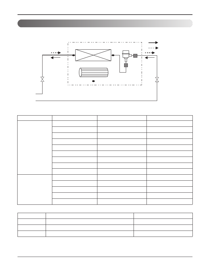
3. Piping Diagrams
[Unit : mm(inch)]
Refrigerant pipe connection port diameter
M2/M3 Chassis
Heat Exchanger
Sirocco Fan
Th3
Th1
Th2
lndoor unit
EEV
:Heating
:Cooling
Filter
Filter
LOC.
Description
PCB Connector (Color)
Th1
Thermistor for room air temperature
CN-ROOM (Yellow)
Th2
Thermistor for pipe in temperature
CN-PIPE_IN (White)
Th3
Thermistor for pipe out temperature
CN-PIPE_OUT (Red)
- 8 -
Copyright © 2018 LG Electronics Inc.
All rights reserved. Only training and service purposes.
CHASSIS
MODEL
GAS
LIQUID
M2
ARNU073M2A4
Ø12.7(1/2)
Ø6.35(1/4)
ARNU093M2A4
Ø12.7(1/2)
Ø6.35(1/4)
ARNU123M2A4
Ø12.7(1/2)
Ø6.35(1/4)
ARNU153M2A4
Ø12.7(1/2)
Ø6.35(1/4)
ARNU183M2A4
Ø12.7(1/2)
Ø6.35(1/4)
ARNU243M2A4
Ø15.88(5/8)
Ø9.52(3/8)
ARNU283M2A4
Ø15.88(5/8)
Ø9.52(3/8)
ARNU363M2A4
Ø15.88(5/8)
Ø9.52(3/8)
ARNU423M2A4
Ø15.88(5/8)
Ø9.52(3/8)
M3
ARNU283M3A4
Ø15.88(5/8)
Ø9.52(3/8)
ARNU363M3A4
Ø15.88(5/8)
Ø9.52(3/8)
ARNU423M3A4
Ø15.88(5/8)
Ø9.52(3/8)
ARNU483M3A4
Ø15.88(5/8)
Ø9.52(3/8)
ARNU543M3A4
Ø15.88(5/8)
Ø9.52(3/8)

- 9 -
Copyright © 2018 LG Electronics Inc.
All rights reserved. Only training and service purposes.
M2 Chassis
M3 Chassis
4. Wiring Diagrams
CN_ROOM(YL)
CN_WF(BL)
CN_PIPE_IN(WH)
CN_PIPE_OUT(RD)
CN_HUMID(OR)
CN_AIRC(BL)
CN_REMO(GN)
CN_PTC(BL)
CN_MOTOR1(WH)
CN_ZONE(WH)
CN_DAMPER(GN)
CN_LEAK(VI)
CN_FLOAT(BL)
CN_EXT(BL)
CN_D_PUMP(WH)
CN_POWER(WH)
CN_CC
(WH)
CN_485(WH)
CN_OPTION
CN_DISPLAY(RD)
CN_EEV(WH)
CN_ROOM(YL)
CN_WF(BL)
CN_PIPE_IN(WH)
CN_PIPE_OUT(RD)
CN_HUMID(OR)
CN_AIRC(BL)
CN_REMO(GN)
CN_PTC(BL)
CN_MOTOR1(WH)
CN_ZONE(WH)
CN_DAMPER(GN)
CN_LEAK(VI)
CN_FLOAT(BL)
CN_EXT(BL)
CN_D_PUMP(WH)
CN_POWER(WH)
CN_CC
(WH)
CN_485(WH)
CN_OPTION
CN_DISPLAY(RD)
CN_EEV(WH)
CN_1(BL)
CN_1(BL)
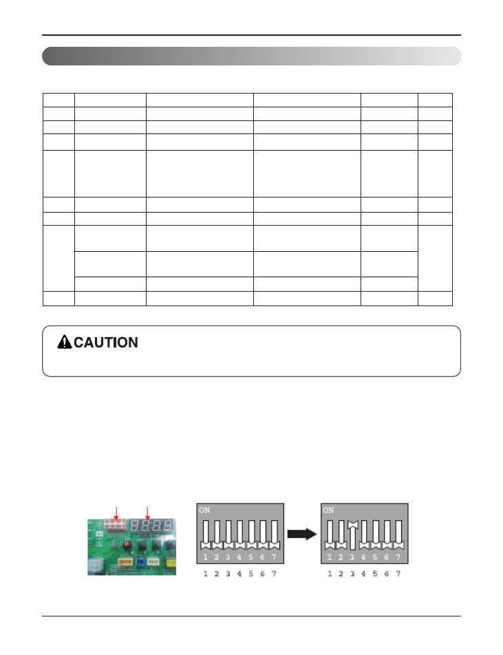
5. DIP Switch Setting
For Multi V Models, DIP switch 1, 2, 6, 8 must be set OFF.
Function Description Setting Off Setting On Default
SW1
SW2
SW3
SW4
SW5
SW6
SW7
SW8
Communication
Cycle
Group Control
Dry Contact Mode
Installation
Heater linkage
Ventilator linkage
Vane selection
(Console)
Region selection
Etc.
N/A (Default)
N/A (Default)
Selection of Master or Slave
Selection of Dry Contact
Mode
Fan continuous operation
N/A
Selection of Ventilator
linkage
Selection of up/down side
Vane
Selection tropical region
Spare
-
-
Master
Wired/Wireless remote
controller
Selection of Manual or Auto
operation Mode
Continuous operation Removall
-
Linkage Removal
Up side + Down side Vane
General model
-
-
-
Slave
Auto
-
-
Working
Up side Vane
Only
Tropical model
-
Off
Off
Off
Off
Off
Off
Off
Off
1. Indoor Unit
2. Outdoor Unit
In case that the products meet specific conditions, “Auto addressing” function can start automatically with the im-
proved speed by turning the DIP switch #3 of the outdoor unit and resetting the power.
* Specific conditions:
- All names of the indoor units are ARNU****4.
- The serial number of Multi V super IV (outdoor units) is after October 2013.
DIP switch 7 segment
Outdoor Unit PCB
Outdoor Unit DIP Switch
- 10 -
Copyright © 2018 LG Electronics Inc.
All rights reserved. Only training and service purposes.
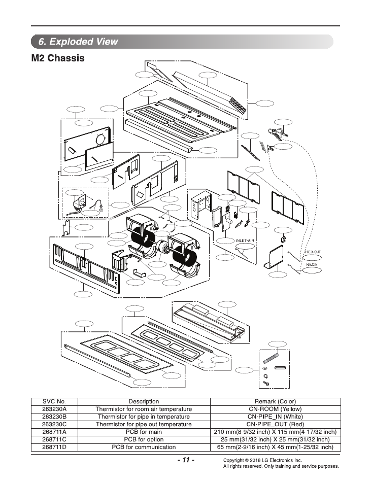
237204B
237204A
147901
137213B
137213A
237200
359012A
135501
159830
739209
73920A
352150B
W50010
W4030B
237205
237202
W4030A
137214
55211G
352118
W4810B
249951
349600A
349610B
359012B
346810
336600A
354210
268711D
261704
W6640A
268711A
268711C
263230B
263230C
137211
437213
263230A
739207
237203
349600B
349610A
336600B
W1JK
330871
W6640C
W4810D
354212
158591
158580
266010
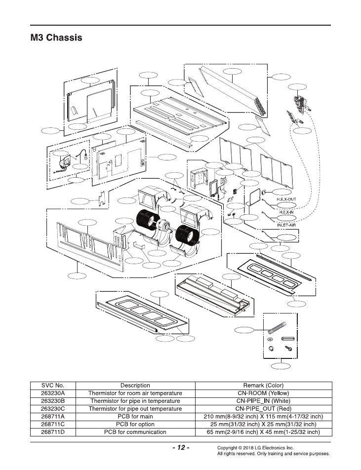
237204A
137213A
147901
349610B
359012A
135501
349600B
159830
336600B
346810
336600A
349600A
W4810A
W4030B
359012B
237205
W4030A
237202
237203
739207
137214
354210
55211G
352118
249951
263230B
263230A
263230C
437213
137211
349610A
268711A
261704
W6640A
W6640C
268711D
W6640A
268711C
W50010
352150B
237200
W6640C
W1JK
237204B
137213B
W4810B
354212
739209
158591
158580
266010
73920A
330871
W4810D

- 13 -
Error Indicator
• This function indicates types of failure in self-diagnosis and occurrence of failure for air condition.
• Error mark is displayed on display window of indoor units and wired remote controller, and 7-segment LED of
outdoor unit control board as shown in the table.
• If more than two troubles occur simultaneously, lower number of error code is first displayed.
• After error occurrence, if error is released, error LED is also released simultaneously.
Error Display
- 1st,2nd,3rd LED of 7-segment indicates error number, 4th LED indicates unit number. Indicates unit number.
(* = 1:Master, 2 : Slave 1, 3 : Slave 2)
Ex) 211 : No.21 error of master unit
213 : No.21 error of slave2
1051 : No.105 error of master unit
h
Refer to the DX-Venitilation manual for DX-Venitilation error code
(repetition)
Error Compressor
Error number
Unit(1:Master, 2:Slave 1, 3:Slave 2)
7. Self-diagnosis function
Display
Title
Cause of Error
Indoor unit related error
0
1
-
Air temperature sensor of indoor unit
Air temperature sensor of indoor unit is open or short
0
2
-
Inlet pipe temperature sensor of indoor unit
Inlet pipe temperature sensor of indoor unit is open or short
0
3
-
Communication error : wired remote controller
↔
indoor unit
Failing to receive wired remote controller signal in indoor unit PCB
0
4
-
Drain pump
Malfunction of drain pump
0
5
-
Communication error : Indoor communication
PCB
↔
indoor unit
Indoor Unit PCB did not receive signal from Indoor
communication PCB for over 3 minutes continuously
0
6
-
Outlet pipe temperature sensor of indoor unit
Outlet pipe temperature sensor of indoor unit is open or short
0
9
-
Indoor EEPROM Error
In case when the serial number marked on EEPROM of
Indoor unit is 0 or FFFFFF
1
0
-
Poor fan motor operation
Disconnecting the fan motor connector / Failure of indoor
fan motor lock
2
3
0
Refrigerant leakage sensing error
Refrigerant leakage sensing error and sensor defect error
2
3
7
Communication defect in indoor communication
PCB
↔
outdoor communication PCB
Indoor communication PCB did not receive signal from outdoor
communication PCB for over 3 minutes continuously
2
3
8
Communication error in outdoor communication
PCB
↔
outdoor unit
Outdoor communication PCB did not receive communication sig-
nal from outdoor unit for over 3 minutes continuously
Copyright © 2018 LG Electronics Inc.
All rights reserved. Only training and service purposes.

P/NO : MFL69041302
Copyright © 2018 LG Electronics Inc. All rights reserved. Only training and service purposes.