Full Text Searchable PDF User Manual

Models SXA1900HX,
SXA2800HX,SXB2800HX,
SXB4000HX, SXB5500HX(S),
SXB7000HX(S)
Gasoline Powered Generators
Owner’s Manual
IMPORTANT:
Do not operate this equipment until you have read and understand all of the
enclosed Owner’s Manuals. Carefully
read all Warnings, Safety Precautions, Assembly
and Operating Instructions, Maintenance and Storage information.
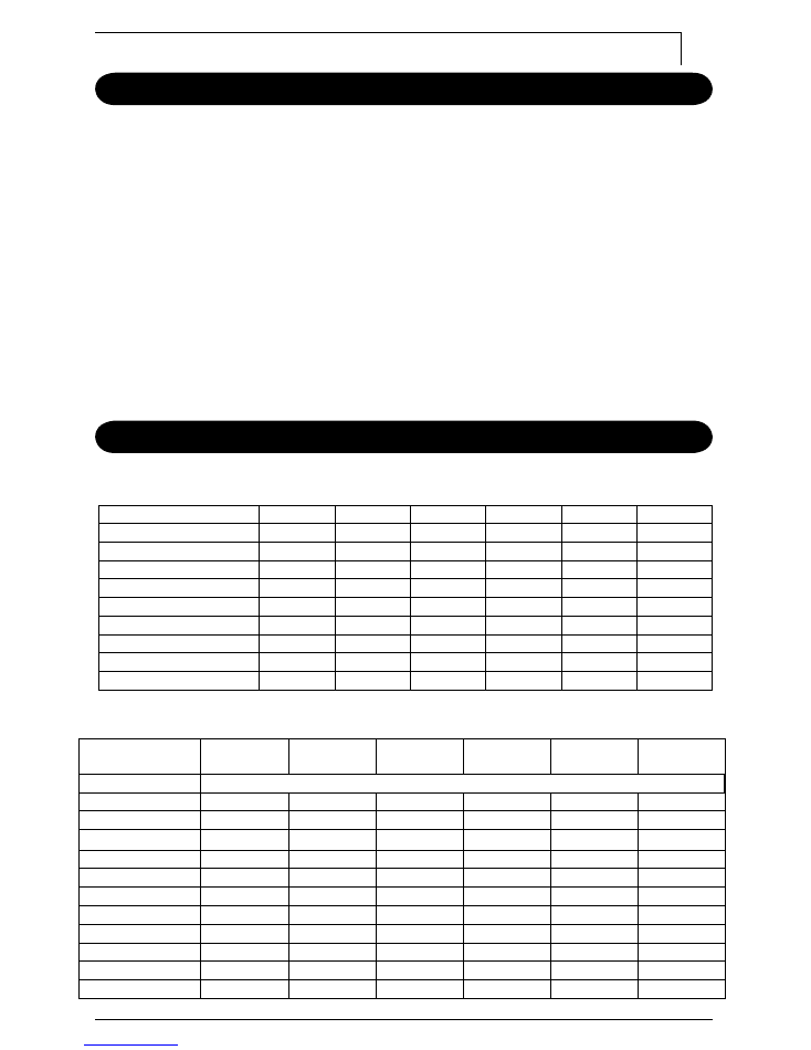
Introduction .......................................................................... 1
Features & Specifi cations ................................................... 1
Safety Precaution ............................................................ 2,3
Before Starting Engine .......................................................... 3
Operation .................................................................... 4,5,6,7
Stopping Operation .............................................................. 8
Maintenance & Storage ........................................................ 8
Wattage Information ............................................................. 9
Troubleshooting ............................................................... 9,10
Customer Service Hotline:
1-800-461-1323
Visit our website:
www.kodiakpower.ca
1
Introduction
Dear Customer:
You are now the proud owner of a Kodiak generator. Kodiak generators are carefully
designed and manufactured to give you
safe
,
dependable
service.
To obtain the best use
of your generator, please read and understand this manual as well as the Honda Engine
Owner’s Manual. Failure to do so could result in personal injury or equipment damage.
Similar to all mechanical products, your machine will occasionally require routine
maintenance. This manual and the Honda Engine Owner’s manual should be read
carefully before operating or performing any adjustments or maintenance on your
machine.
This manual as well as the Honda Engine Owner’s manual should be considered a
permanent part of the generator and should always remain with the unit.
All information contained in this manual refl ects the latest product data at the time of
publication. Specifi cations are subject to change without prior notifi cation or obligation.
Features & Specifi cations
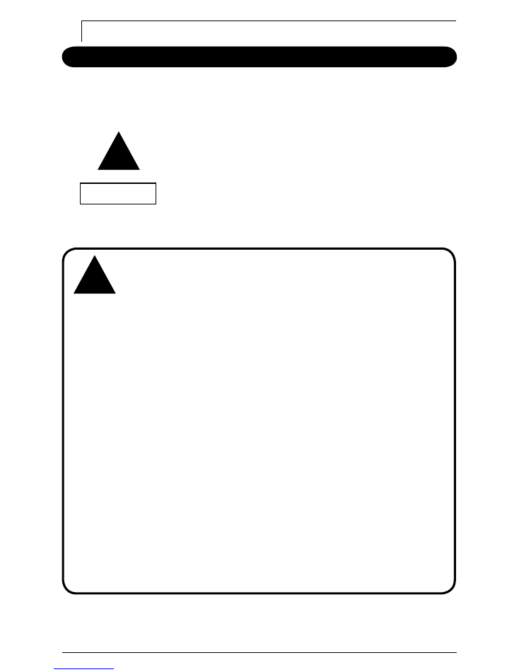
SXA1900
SXA2800
SXB2800
SXB4000
SXB5500
SXB7000
Honda OHV Engine
Full Frame Protection
Oil Alert
Automatic Idle Control
Voltmeter
Voltage Regulator
DC Output
No-Fuse Breaker
Optional Electric Start
Model
SXA1900HX
SXA2800HX
SXB2800HX
SXB4000HX
SXB5500HX/
SXB5500HXS
SXB7000HX/
SXB7000HXS
Generator Type
Brushless, self exciting 2 pole single phase
Engine: Model
GX120
GX160
GX160
GX240
GX340
GX390
HP
4
5.5
5.5
8
11
13
Tank Capacity
US gal (l)
0.66 (2.5)
0.95 (3.6)
2.90(11)
4.49(17)
4.49(17)
4.49(17)
Operating Hours
3.3
3.0
8.3
8.5
5.8
5.2
AC Output
120V
120V
120V
120/240V
120/240V
120/240V
Rated Output
1600W
2400W
2400W
3600W
4500W
5700W
Rated Amps
13.3A
20A
20A
30/15A
37.5/18.8A
47.5/23.8A
DC Output
N/A
N/A
12V
12V
12V
12V
Dimensions (mm)
555x395x390
545x415x405
545x425x420
645x500x500
665x515x505
680x515x505
Dimensions (inches)
21.8X15.6X15.3
21.5X16.3X15.9
21.5X16.7X16.5
25.4x19.7x19.7
26.2x20.3x19.9
26.8x20.3x19.9
Dry Weight lbs. (kg)
65 (30)
76 (35)
93(43)
148(68)
163(75)/174(80)
176(81)/186(86)
A. Features of the full range of Kodiak generators
B. Specifi cations*
* subject to change without notifi cation
2
Safety Precaution
CAREFUL OPERATION IS YOUR BEST INSURANCE AGAINST ACCIDENT!
Read carefully and understand this section before operating your generator. All operators,
no matter how much experience they have had, should read this and other manuals
included with your machine. It is the owner’s obligation to instruct all operators in safe
operation.
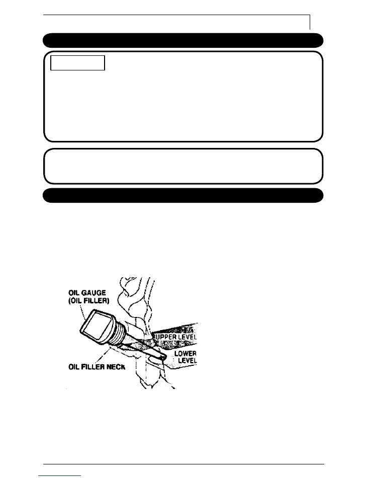
Indicates a possibility of personal injury or equipment
damage if instructions are not followed.
Indicates that equipment or property damage can result
if instructions are not followed.
CAUTION:
Indicates that equipment or property damage can result
if instructions are not followed.
NOTICE
1. Read this manual and the Honda Engine Owner’s manual carefully
before using your new generator -
KNOW YOUR EQUIPMENT!!!
2.
DO NOT
operate generator in the rain or with wet hands.
If you ignore this condition, you may suffer severe electric shock.
3.
REFUELING
a.
DO NOT
refuel the generator while it is in operation
or still hot.
b.
DO NOT
refuel while smoking or near fl ames, pilot lights,
sparking electrical devices, etc. (e.g. power tools, welders,
or grinders) Unit should be refueled in a well lighted,
& well ventilated area.
c. Avoid spillage.
d.
DO NOT
operate this generator with any other fuel
except gasoline.
4.
DO NOT
operate generator near infl ammable products.
5.
DO NOT
operate in areas with poor ventilation where vapors may
be trapped.(i.e. inside a room or tunnel)
Engine exhaust gases are dangerous - the exhaust fumes contain
carbon monoxide, a poisonous, tasteless, odorless, and invisible gas.
The exhaust gases will endanger lives.
6.
DO NOT
connect the unit to a commercial power line.
7.
DO NOT
operate any generators with missing or broken parts.
Contact your dealer for replacement parts.
8.A ground should be used in damp or highly conductive locations.
9.
DO NOT
operate with extensions, power cords or any other electrical
equipment, which is damaged or defective. Never operate any
electrical equipment with damaged or defective cords.
!
WARNING
!
WARNING
3
Safety Precaution
CAUTION:
1. Operate your unit only on a fi rm supporting, level surface.
2. Sophisticated electronics (ie computers, phone systems…etc)
should not be connected to this type of generator.
1. Fill Engine with oil. Refer to the Honda Engine Owner’s
Manual for oil recommendations.
2. This Honda engine has an OIL ALERT system to protect the
engine against low oil level. If the engine oil level is low the
engine will not start.
3. Do not cover the unit while in operation. It could cause
overheating and result in equipment damage.
4. For storage, do not cover unit until the engine has cooled
completely.
5. Ambient temperature should not exceed 100
o
F/40
o
C.
NOTICE
Before Starting Engine
Read and understand the Honda Engine Owner’s Manual
Check and fi ll engine with the recommended engine oil to the proper level.
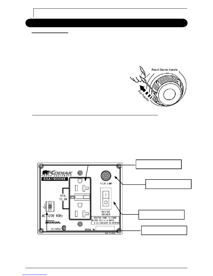
Change oil if it becomes dirty or discolored. (Diagram 1) Oil capacity at upper level
mark on the oil dipstick: see Honda engine owner’s manual for more information.
Remove the tank cap and check the fuel level. If fuel level is low, refi ll with unleaded
automotive gasoline.
Diagram 1:
Inspecting oil capacity.
4
Operation
Starting the engine
:
1. Read Honda Engine Owner’s Manual.
2. Open fuel cock.
3. Set choke lever towards the “
close
” position when engine is cold.
If engine is warm, choke lever should be moved to the "
Open
” position.
4. Set the engine switch to the “
run
” position.
5. Pull on starter rope with a fast steady pull to start the engine. (Diagram 2)
6. After engine has started, move the choke
lever back gradually to the “
Open
” position.
7. Once the engine is running at normal
speed, useable AC power is available.
Diagram 2:
Starting the engine.
Applying AC load (single voltage type) (Refer to Diagrams 3, 4, 5.)
:
1. Place generator’s “
no fuse breaker
” switch in the “
0
" position.
2. Start engine (Please refer to the Honda Engine Owner’s Manual.)
3. Allow the engine to warm up for 2 - 3 minutes before connecting tools
or appliances.
4. Insert the plug of the electrical appliance into the “
AC receptacle
”.
5. Place generator’s “
no fuse breaker switch
” in the “
1
” position.
6. Reset the GFCI receptacle.
Diagram 3:
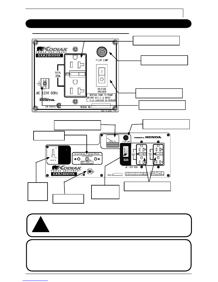
SXA1900HX AC Panel
Tee Slot GFCI Receptacle
“Power On” Indicator Light
No Fuse Breaker
Ground Terminal
5
Operation
Applying AC load (single voltage type) coninued:
Diagram 5:
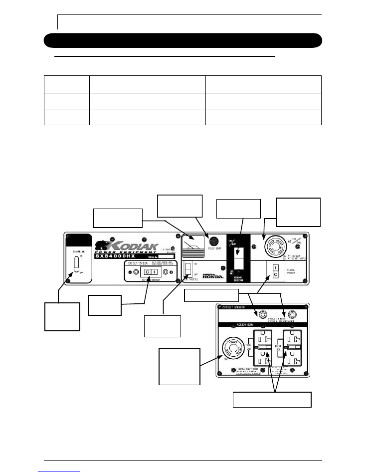
SXB2800HX AC Panel
Be sure to ground the generator if the connected electrical equipment
is grounded.
CAUTION:
When the generator is overloaded or a short circuit is made, the
‘
no-fuse breaker”
switch will stop the engine to protect the circuit
automatically. If the “
no-fuse breaker”
switch trips during operation,
the generator is either over loaded or the appliance is defective.
Check the appliance and/or generator for overloading or defect, make
necessary corrections or repairs before use.
Diagram 4:
SXA2800HX AC Panel
No Fuse Breaker
Ground Terminal
Tee Slot GFCI Receptacle
“Power On” Indicator Light
!
WARNING
Output Voltage Meter
“Power On” Indicator Light
Tee Slot GFCI Receptacle
No Fuse
Breaker
12V DC Output
Ground Terminal
Engine
“ON/OFF”
Switch
6
Operation
Dual voltage type (SXB4000HX,SXB5500HX(S),SXB7000HX(S) only)
1. Select the voltage using the "select" switch in accordance with the electrical
appliance. Refer to table below.
SWITCH
LOWER VOLTAGE RECEPTACLE
HIGHER VOLTAGE RECEPTACLE
110V or 120V
RATED OUTPUT IS AVAILABLE
UNAVAILABLE
110V/220V or
120V/240V
HALF OF RATED OUTPUT IS AVAILABLE
RATED OUTPUT IS AVAILABLE
2. Place generator’s “
no fuse breaker
” switch in the “
0
" position.
3. Start engine (Please refer to the Honda Engine Owner’s Manual.)
4. Allow the engine to warm up for 2 - 3 minutes before connecting tools
or appliances.
5. Insert the plug of the electrical appliance into the “
AC receptacle
”.
6. Place generator’s “
no fuse breaker switch
” in the “
1
” position.
7. Reset the GFCI receptacle.
Diagram 6:
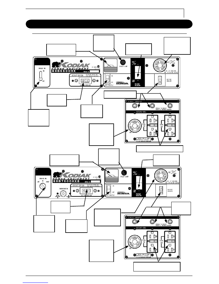
SXB4000HX Control Panel
120 Volt
Twist Lock
Receptacle
NEMA L5-30R
Tee Slot GFCI Receptacle
Auto Throttle
Switch
12V DC
Output
Engine
“ON/OFF”
Switch
Output Voltage
Meter
“Power On”
Indicator Light
Output voltage
selector switch
4 wire Twist
lock receptacle
NEMA L14-30R
No Fuse Breaker
7
Operation
Dual voltage type (SXB4000HX,SXB5500HX(S),SXB7000HX(S) only) continued:
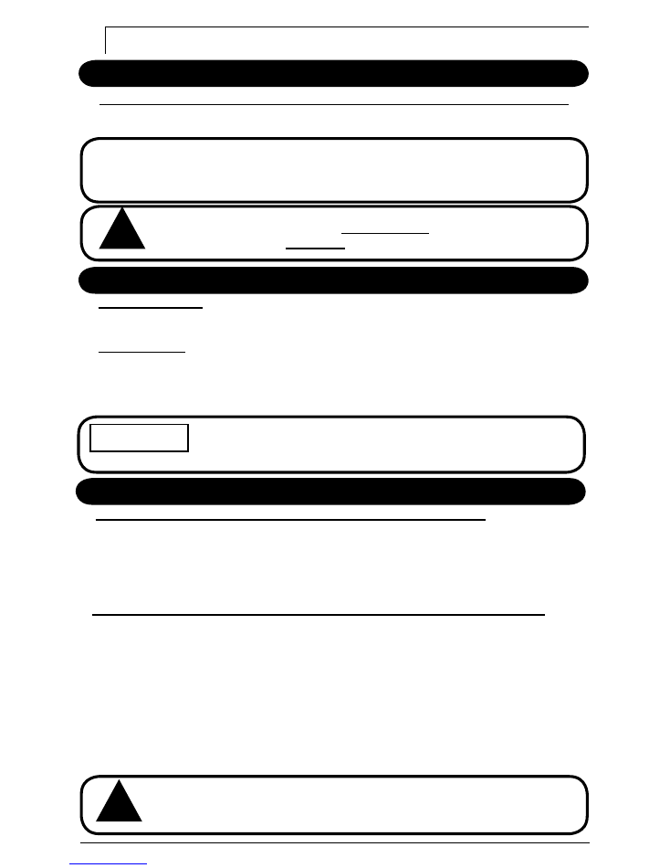
Diagram 7:
SXB5500HX Control Panel
Diagram 8:
SXB7000HX Control Panel
Tee Slot GFCI Receptacle
120 Volt
Twist Lock
Receptacle
NEMA L5-30R
Auto Throttle
Switch
12V DC
Output
Engine
“ON/OFF”
Switch
Output Voltage
Meter
“Power On”
Indicator
Light
Output voltage
selector switch
4 wire Twist
lock receptacle
NEMA L14-30R
No Fuse Breaker
Tee Slot GFCI Receptacle
120 Volt
Twist Lock
Receptacle
NEMA L5-30R
Auto Throttle
Switch
12V DC
Output
Engine
“ON/OFF”
Switch
Output Voltage
Meter
“Power On”
Indicator
Light
No Fuse
Breaker
4 wire Twist
lock receptacle
NEMA L14-30R
Output voltage
selector switch
8
Battery charger (SXB2800HX,SXB4000HX,SXB5500HX(S),SXB7000HX(S) only)
The DC terminal is used only for charging 12 volt batteries. It provides up to
12V-8.3A(100W) of maximum power.
Operation
CAUTION:
Be sure to make correct connection to the battery.
The positive(+) battery terminal should be connected to the "
red
"
terminal.
Do not
over-charge the battery.
Over-charging
of a battery can result in
personal injury due to
explosion
of battery.
Stopping Operation
In an emergency:
(Please refer to the Honda Owner’s manual)
To stop the engine in an emergency, move the engine switch to the "
off
” position.
In normal use:
1. Turn the “
no-fuse
” breaker to the “
0
” position.
2. Unplug all appliances.
3. Move the engine switch to the “
off
” position.
4. Turn the fuel valve to the “
off
“position.
Never leave an appliance plugged into the generator when you
stop the generator, as damage could result to the generator and/or
appliance.
NOTICE
Maintenance & Storage
Maintenance (Please refer to the Honda Engine Owners Manual):
Periodic inspection and adjustment of the Honda engine are essential if a high level of
performance is to be maintained. Regular maintenance will also ensure a long service
life. The required service intervals and kind of maintenance to be performed are
described in the Honda Engine Owner’s Manual. Please refer to the Honda Engine
Owner’s Manual for more details.
Transportation/Storage (Please refer to the Honda Engine Owners Manual):
When transporting the generator, turn the fuel cock OFF and keep the unit level
to prevent fuel spillage.
When the generator is in storage for a long period, carry out the following maintenance.
Please refer to the Honda Owner’s manual.
1. Store generator in a well-ventilated, low humidity area.
2. Clean each part with an oil permeated rag.
3. Change the engine oil.
4. Clean the air cleaner.
5. Empty the gasoline from fuel tank.
6. Start and run engine until the it runs out of fuel.
Never use water to clean the generator
!
WARNING
!
WARNING
9
Wattage Information
Some appliances need a “
surge
” or “in rush” of power at start up. This means that the
amount of electrical power needed to start the appliance may exceed the amount needed
to maintain its use. Refer to the appliance for its maximum starting power.
Electrical appliances and tools normally come with a label indicating voltage, cycles (HZ),
amperage and electrical power needed to run the appliance or tool. If the appliance
does not have this information in watts - but does have it in voltage & amperage - simply
multiply them together to get the power in watts.
(Power in watts = voltage x amperage)
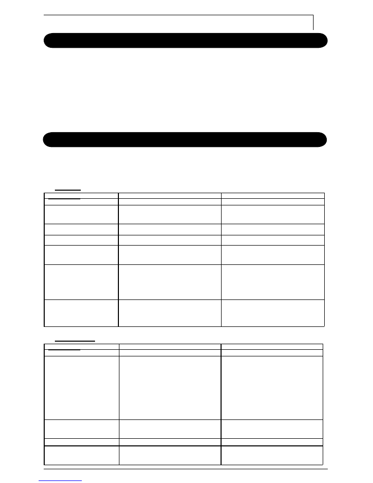
Troubleshooting
The majority of troubles with generator units are with the engine. Please refer to the
Honda Engine manual if engine troubles arise. If problem persists please contact your
local Honda dealer.
Engine:
Symptom
CAUSE
REMEDY
Engine fails to start
Fuel level is low
Refi ll fuel tank making sure
not to overfi ll
Oil Level is low
Fill oil to proper level
Fuel strainer cock closed
Open fuel strainer cock
Choke lever is not in the
proper position
Place chose lever “close”
Spark plug loose or dirty
1. If loose, push spark plug
cap back into place
2. Remove spark plug and
clean electrodes
Others
See Honda owner’s manual
or contact your local Honda
Dealer for assistance
Generators:
Symptom
CAUSE
REMEDY
No Power
No-fuse breaker is “0”
position
After making sure that
the total wattage of the
electrical appliance is with
in permissible limits and
there are no defects in the
appliance, turn the no-fuse
breaker to the “1” position
The GFCI receptacle has
tripped or has not been set
Press the reset button in the
GFCI receptacle
Voltage is too low
Engine speed is too low
Contact your local Kodiak
dealer for assistance

10
Troubleshooting
If problem persist please call the Kodiak toll free hot-line below for the service
center nearest you.
Customer Service Hotline:
1-800-461-1323
Visit our website:
www.kodiakpower.ca

2005.4
GENERATOR
PARTS CATALOG
MODEL : GESXB5500HX(S) (CSA)
4500VA 120/240V 60Hz
No.GESXB5500HX(S)
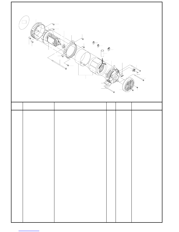
No.2R-06125
1
GESG15411460000
BRACKET
(1)
1
2
GESG15311462000
N-BRACKET
1
3
GESG15311461000
BRACKET
(2)
1
4
GESG15200347000
ROTOR
ASSY
1
L#20212122
5
GESG15250222000
STATOR
ASSY
1
L#20212119
6
GESG1531E471000
COVER,BRACKET
1
7
GESG6205ZZ-CM-NS7 BALL
BEARING
1
8
GESGK4403005
RUBBER
BUSH
1
9
GESG15111473000
BRIDGE
DIODE
1
10
GESGK3403011
HEX,BOLT
W/FLANGE(M10×1.25-250
)
1
11
GESGK3403015
HEX,BOLT
W/FLANGE(M6×1.0-165
)
4
12
GESG19B30908020
HEX,BOLT
W/FLANGE(M8×1.0-20
)
4
13
GESG19B30905012
HEX,BOLT
W/FLANGE(M5×0.8-12
)
2
14
GESG19B50908020
FLAT
HEAD
BOLT
W/SOCKET
(
M8×1.25-20)
4
15
GESG19S00904018
CROSS
RECESSED
HEAD
SCREW(M4-18
)
1
16
GESG19S00905007
CROSS
RECESSED
HEAD
SCREW(M5-7
)
1
17
GESG15350107000
TUBE,LEAD
WIRE(L=240)
1
18
GESG15350101000
CONNECTOR
4P
凸
2
19
GESG15350307000
CONNECTOR
6P
凸
1
ALTERNATOR
GESXB5500HX(S)
REF No.
Remarks
Parts No.
Parts name
Q'ty
Price
E/G
1
14
14
14
14
7
2
4
12
10
12
12
12
19
17
18
19
8
5
3
16
11
6
13
13
11
15
9
11
ALTERNATOR
1
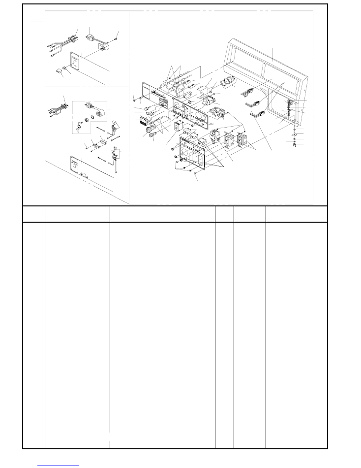
No.2R-06125
1
CONTROL
BOX
ASSY
1
2A
GESG15450758000
PANEL
1
2B
GESG15450759000
PANEL
1
3
GESG15450768000
PANEL
1
4
GESG15300837000
CONTROL
PANEL
1
5
GESG15400104000
RECEPTACLE
20A
、
GFCI
2
6
GESG15400105000
RECEPTACLE
30A
、
3P
1
7
GESG15400106000
RECEPTACLE
30A
、
4P
1
8
GESG15400144000
NO-FUSE
BREAKER
(250V,20A)
2
9
GESG85111573300
NEON
BRACKET
1
10
GESG15400143000
SWITCH,VOLTAGE
SELECTOR
1
11
GESG15400108000
SWITCH,AUTO
THROTTLE
1
12
GESG19600700660
CONTROL
UNIT,AUTO
THROTTLE
1
13
GESG15111584000
D.C
TERMINAL
RED(+)
1
14
GESG15111583000
D.C
TERMINAL
BLACK(
-
)
1
15
GESG15400141000
NO-FUSE
BREAKER
DC
10A
1
16
GESG85321072000
LEAD
WIRE
ASSY,AUTO
THROTTLE
1
17
GESG15111585020
FUSE
1A
1
18
GESG15400142000
TWIN
NO-FUSE
BREAKER
(250V,20A)
1
19
GESG15450145000
NO-FUSE
BREAKER
(250V,30A)
1
20
GESG15400109000
VOLTMETER,FS:300V
1
21
GESG89700581050
CONDENSOR
ASSY,
18μ
F
2
22
GESG15350101000
CONNECTOR
4P
凹
2
23
GESG15350307000
CONNECTOR
6
P
凹
1
24
GESG36110-ZB4-701
SWITCH ASSY,ENGINE STOP
1
HONDA PART
25
GESG15500981000
LEAD
WIRE
ASSY,ENGINE
SWITCH
1
26
GESG35100-ZB4-013
KEY SWITCH ASSY,COMBINATION
1
HONDA PART
27
GESG32130-ZE1-000
COUPLER COMP,SILICON RECTIFIER
1
HONDA PART
CONTROL BOX
GESXB5500HX(S)
Price
Remarks
REF No.
Parts No.
Parts name
Q'ty
26
30
28
27
29
37
36
2B
SXB5500HXS ONLY
SXB5500HX ONLY
25
2A
24
38
39
40
CONTROL BOX
23
21
32
31
12
20
31
20
33
4
9
32
42
44
45
43
47
3
6
5
7
8
9
10
11
14
13
13
14
15
17
16
18
19
22
31
33
33
34
41
43
49
43
49
46
49
1
35
48
15
2
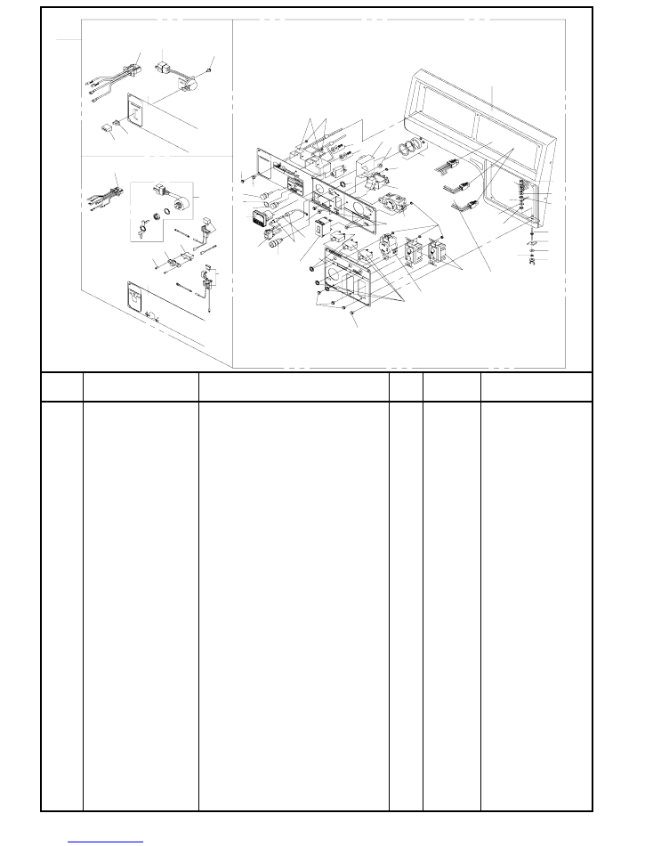
No.2R-06125
28
GESG38220-ZE1-000
CASE COMP,FUSE
1
HONDA PART
29
CIRCUIT PROTECTOR (1A、125V)
1
HONDA PART
30
GESG15500982000
LEAD WIRE ASSY,COMBINATION SWITCH
1
31
GESG19S00904012
CROSS RECESSED HEAD SCREW (M4-12)
12
32
GESG19S00905010
CROSS RECESSED HEAD SCREW (M5-10)
10
33
GESG19N10904000
HEX,NUT W/FLANGE M4
12
34
GESG19SF4906015
CROSS
RECESSED
HEAD
SCRED
(M6-15)
1
35
GESG19N10906000
HEX,NUT
W/FLANGE
M6
1
36
GESG19S00903012
CROSS RECESSED HEAD SCREW (M3-12)
2
37
LENS ASSY,PROTECTOR
1
HONDA PART
38
GESG32343-892-003
KNOB,CONTROL
LEVER
1
HONDA PART
39
GESG36106-892-003
BUSH,CONTROL
KNOB
1
HONDA PART
40
GESG19S00904006
CROSS
RECESSED
HEAD
SCRED
(M4-6)
1
41
GESG15500958000
EARTH
WIRE
1
1
42
EARTH
WIRE
2
1
43
FLAT WASHER(5)
3
44
GESG15550168000
STUD BOLT (M5)
1
45
GESG15301034000
CAP WASHER
1
46
LOCK WASHER(5)
1
47
GESG19N60905000
WING NUT (M5)
1
48
LEAD WIRE
1
49
GESG19N10905000
HEX,NUT W/FLANGE (M5)
3
Price
Remarks
REF No.
Parts No.
Parts name
Q'ty
CONTROL BOX
GESXB5500HX(S)
26
30
28
27
29
37
36
2B
SXB5500HXS ONLY
SXB5500HX ONLY
25
2A
24
38
39
40
CONTROL BOX
23
21
32
31
12
20
31
20
33
4
9
32
42
44
45
43
47
3
6
5
7
8
9
10
11
14
13
13
14
15
17
16
18
19
22
31
33
33
34
41
43
49
43
49
46
49
1
35
48
15
3
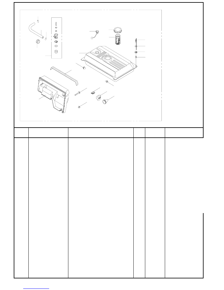
No.2R-06125
1
GESG15300838000
FUEL TANK
1
2
GESG15321771100
FILTER COMP., FUEL
1
3
GESG15321771000
CAP COMP., FUEL FILLER
1
4
GESG15321278000
GAUGE ASSY., FUEL
1
5
GESG15221880110
RUBBER,TANK
MOUNTING
2
6
GESG15321880100
RUBBER,TANK
CUSHION
2
7
GESG19B30906022
HEX,BOLT
W/FLANGE
(M6×1.0-22)
2
8
GESG15321670270
COLLAR,TANK
CUSHION
2
9
GESG19W00906025
WASHER,TANK
CUSHION
(6×25,1.0t)
2
10
GESG16950-ZB4-0150
COCK
COMP
、
FUEL
1
11
GESG90854-ZB2-0000
RUBBER,FUEL
TUBE
1
12
GESG95001-45150-40
TUBE,FUEL
1
13
GESG95002-02080
CRIP
B8,TUBE
2
14
GESG15350202000
CASE,CONTROL
1
15
GESG19B30906040
HEX,BOLT
W/FLANGE
(M6×1.0-40)
3
16
GESG15321880150
RUBBER,CONTROL
CASE
1
17
GESG90101-692-000
SCREW
GROVE
BOX
1
HONDA
PART
18
GESG15321880130
GROMMET
PANEL
LEAD
#2
1
19
GESG15321880160
GROMMET
SWITCH
CODE
1
20
GESG15321880140
GROMMET
TUBE
1
Price
Remarks
REF No.
Parts No.
Parts name
Q'ty
FUEL TANK
GESXB5500HX(S)
HONDA
PART
HONDA
PART
HONDA
PART
HONDA
PART
3
1
2
4
5
5
6
8
7
9
10
11
12 13
13
FUEL TANK
14
16
20
19
18
15
17
4
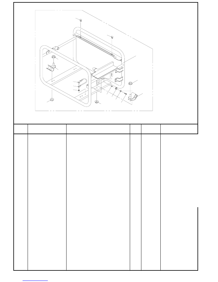
No.2R-06125
1
GESG15321670001
FRAME
1
2
GESG19500691010
ANTI-VIBRATION RUBBER
4
3
GESG19N15910000
HEX, NUT W/FLANGE (M10×1.25)
4
4
GESG19N10908000
HEX, NUT W/FLANGE (M8×1.25)
4
5
GESG15321880120
STOPPER,DISCHARGE GURD
2
6
GESG19B30906012
HEX, BOLT W/FLANGE (M6×1.0-12)
1
7
GESG15500377000
BONDING
WIRE
1
8
GESG19W50906000
TOOTH
LOCK
WASHER
(6)
1
9
GESG19B30906020
HEX, BOLT
W/FLANGE (M6
×1.0-20)
3
10
GESG19W00906020
WASHER,PANEL CUSHION (6×20,1.0t)
3
11
GESG15221880100
RUBBER,PANEL CUSHION
3
12
GESG15221670270
COLLAR,PANEL CUSHION
3
FRAME
GESXB5500HX(S)
Price
Remarks
REF No.
Parts No.
Parts name
Q'ty
FRAME
5
3
10
3
2
1
4
12
11
9
4
2
6
7
8
5
5