Full Text Searchable PDF User Manual
User’s Manual
Installation, Operations,
Maintenance and Parts
Part No. 6004751K
Do not install, operate or service this product unless you
have read and understand the Safety Practices, Warnings,
Installation and Operating Instructions contained in this
User’s Manual. Failure to do so could result in death or
serious injury.
This User’s Manual applies to
aFX dock levelers manufactured
beginning September 2012 with
the serial numbers 61056056
and higher.
aFX
®
/aFX-S Dock Leveler
©2012 4Front Engineered Solutions, Inc.
August 2012
6004751K — aFX
®
and aFX-S Dock Leveler — Safe
T
Frame
®
15
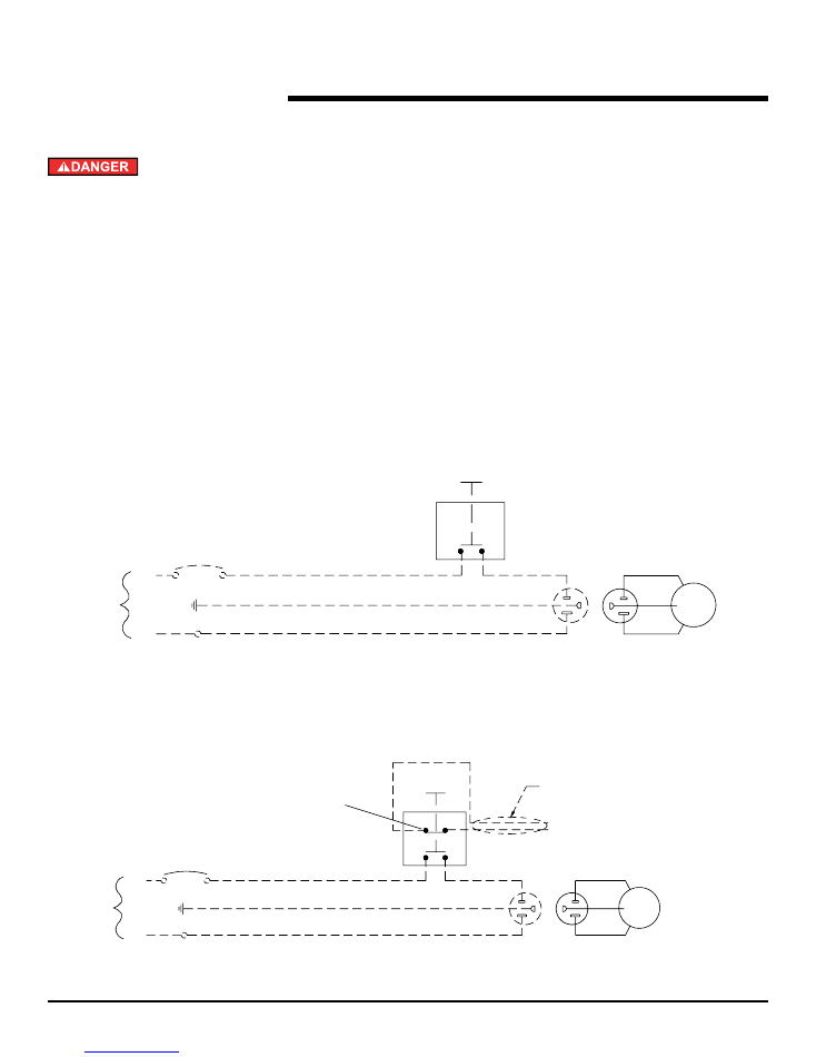
wiring DiagraM
Before doing any electrical work, make certain the power
is disconnected and properly tagged or locked off. All
electrical work must be done by a qualified technician
and meet all applicable codes. If it is necessary to make
troubleshooting checks inside the control box with the
power on, USE EXTREME CAUTION. Do not place your
fingers or non insulated tools inside the control box.
Touching wires or other parts inside the control box
could result in electrical shock, death or serious injury.
Never allow more than 130 volts to be connected to the
120 volt motor circuit. Damage to motor, push-button, air
bag, and serious personal injury or death may result.
Optional Blue Contact Block
(Normally Closed)
Field Installed (Low Voltage Only)
See Supplied Mfg. Instructions
Control
Station
Control
Station
Optional connection to restraint
Star4 LA terminals C and 17.
For Star4 module with 403 controller
use 21 and 22
To:
Auto chock terminal block
terminals no. 5 and no. 24
Pit Wall
Receptacle
NEMA 5-15R
(By Others)
Pit Wall
Receptacle
NEMA 5-15R
(By Others)
1 Phase 120V
50/60 Hz
1 Phase 120V
50/60 Hz
BLK
WHT
GRN Motor
BLK
WHT
GRN Motor
Circuit Breaker
(By Others)
20 AMP MAX
Circuit Breaker
(By Others)
20 AMP MAX
Line
Line
Grn
Grn
Neutral
Neutral
120V
1 Phase
50/60 Hz
120V
1 Phase
50/60 Hz
120V, Single Phase, 50/60 Hz
Optional Dual Contact
120V, Single Phase, 50/60 Hz
Single Contact
Fig. 23
©2012 4Front Engineered Solutions, Inc.
22
6004751K — aFX
®
and aFX-S Dock Leveler — Safe
T
Frame
®
August 2012
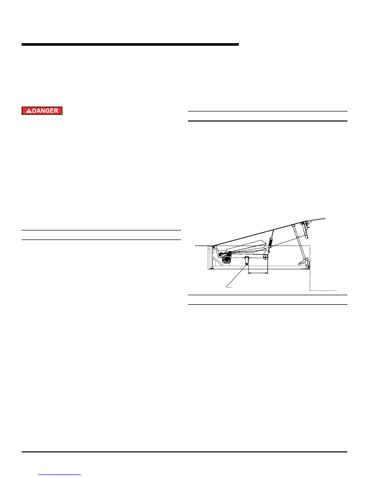
SerVice TooLS
Before servicing the dock leveler, read and follow the
Safety Practices on page 3, and the Operations Instruction
section on pages 16 through 18 of this User’s Manual.
Be certain, before climbing into the dock leveler pit or
doing any maintenance or repair under the dock leveler,
that: 1) THE MAINTENANCE STRUT AND LIP LOCK ARE
SECURELy PINNED IN PLACE [see Fig. 31 and text below]
and 2) The power is disconnected and properly tagged
or locked off.
Air pressure or mechanical support must be maintained
on the ramp to hold it in the raised position until the
maintenance strut is in place. DO NOT WORK UNDER
THE DOCK LEVELER RAMP OR LIP UNLESS THE
MAINTENANCE STRUT AND LIP LOCK ARE PINNED IN
PLACE.
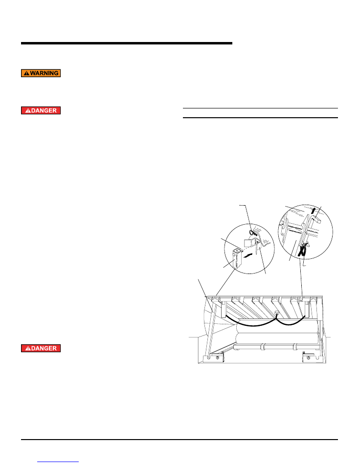
MainTenance STrUT
1. Two people are needed to place the dock leveler on the
maintenance strut.
a. One person must push and hold the raise button
until dock leveler reaches its highest position and
hold dock leveler in its highest position.
b. The second person positions the maintenance strut
into the bracket located on the underside of the ramp
assembly and pins it in place with hairpin clip. See
Fig. 31 and the instruction label on maintenance
strut.
c. The raise button may now be released.
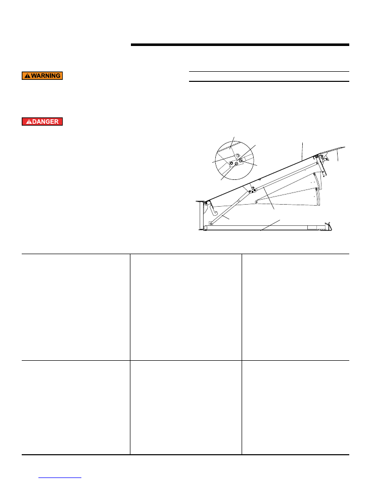
Lip LocK
Manual support of lip must be maintained until the lip
lock is in place. The lip is free to move downward when
it is released unless lip lock is pinned in place.
DO NOT WORK UNDER THE DOCK LEVELER RAMP OR
LIP UNLESS THE MAINTENANCE STRUT AND LIP LOCK
ARE PINNED IN PLACE.
Fig. 31
Maintenance
strut bracket
Insert hairpin
clip through
maintenance
strut pin
Maintenance
strut pin
Lip
lock
Lip
Insert
hairpin
clip into
lip lock
Ramp
Maintenance
strut
1. Manually lift the hinged lip into the raised position and
lock into place with the lip lock provided on the dock
leveler ramp. Pin lip lock in place with hairpin clip. See
Fig. 31 and instruction label located on the underside of
the dock leveler ramp.
noTe:
To store the maintenance strut follow all instructions on
page 12.
©2012 4Front Engineered Solutions, Inc.
August 2012
6004751K — aFX
®
and aFX-S Dock Leveler — Safe
T
Frame
®
23
SerVice TooLS,
continued
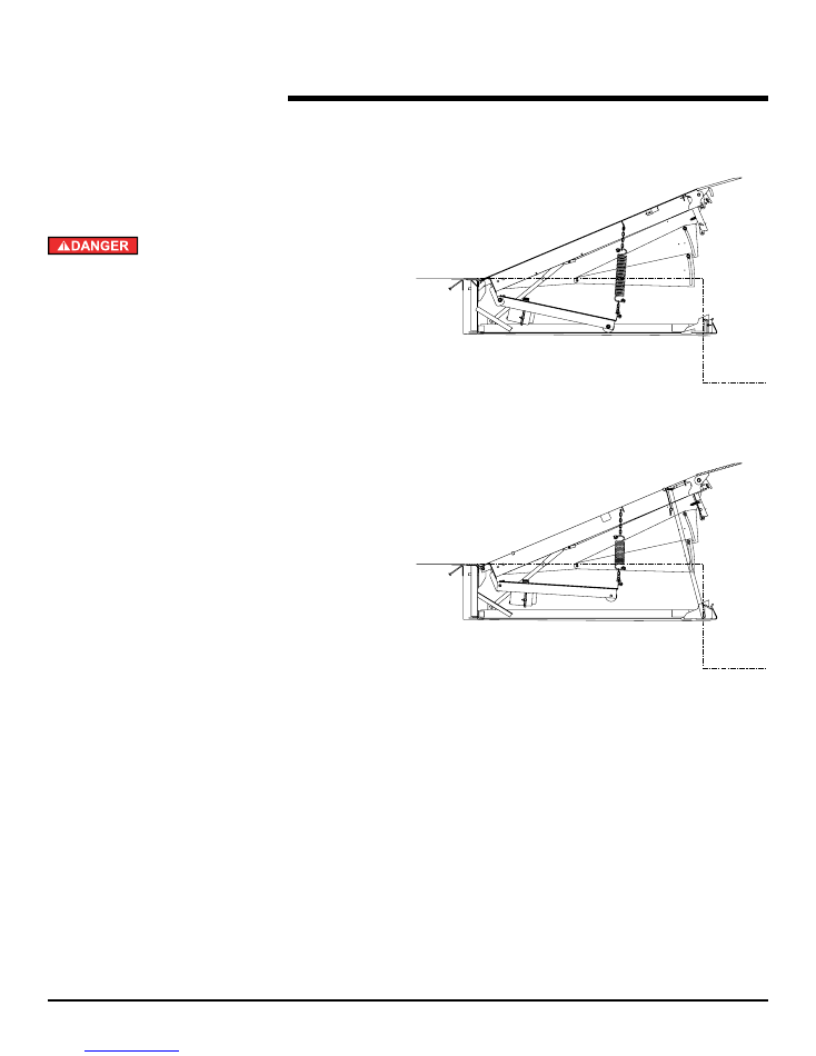
cLean piT KiT
The clean pit kit is used to raise the front end of the bag
support pan assembly. This allows for easy access to the pit
for cleaning of the pit area.
Be certain, before climbing into the dock leveler pit or
doing any maintenance or repair under the dock leveler,
that: 1) THE MAINTENANCE STRUT AND LIP LOCK ARE
SECURELy PINNED IN PLACE [see page 22] and 2) The
power is disconnected and properly tagged or locked off.
The clean pit kit as shown will automatically raise the bag
support pan assembly when the dock leveler it rested on the
maintenance post. Reference the chart on page 34 for the
upper shackle location on the chain to determine the proper
link for connecting the kit to the ring on the deck.
During normal operation, the spring extends as the bag
inflates. See Fig. 32
When pinned on the maintenance strut, the spring will raise
the bag support pan assembly as the bag deflates. Once the
bag pan support assembly stops moving, there is then easy
access for cleaning the pit or installing the bag removal tools
for removing the bag. See Fig. 33
Fig. 32
Fig. 33
©2012 4Front Engineered Solutions, Inc.
24
6004751K — aFX
®
and aFX-S Dock Leveler — Safe
T
Frame
®
August 2012
SerVice TooLS,
continued
pan reMoVaL roLLerS
The pan removal rollers are used to remove the bag support
pan assembly. This allows for easy access to service the lifting
fan and bag assembly.
Be certain, before climbing into the dock leveler pit or
doing any maintenance or repair under the dock leveler,
that: 1) THE MAINTENANCE STRUT AND LIP LOCK ARE
SECURELy PINNED IN PLACE [see page 22] and 2) The
power is disconnected and properly tagged or locked off.
1. To remove bag support pan assembly:
1.1 Allow the lifting spring to deflate the air bag and raise
the bag support pan assembly.
1.2 Attach pan rollers (kit part #184376 for 19" subframes
and 6013799 for 23" subframes) to both sides of the
pan assembly, either 16" or 19" back from the front
edge as shown in Fig. 34.
noTe:
For 8' long 50K capacity and 10' long dock levelers attach pan
rollers 19" from front edge as shown in Fig. 34.
1.3 After installing the rollers, press down on the front of
the bag assembly, extending the spring, to unhook the
rear axle from the back of the leveler and pull forward.
1.4 Disconnect the bolt from the center pan and remove
the lifting kit from the bag support pan assembly.
1.5 Balancing the bag support pan assembly on the rollers
roll it to the front of the pit. The rollers will roll on the
frame rails.
2. To install the bag pan assembly:
2.1 Roll the bag support pan assembly to the back of the
pit and align it with the hooks on the back of the ramp.
2.2 Tilt the front of the assembly up and attach the support
angle that is connected to the bottom of the lifting kit
to the hole in the center pan.
2.3 Press the front of the bag down and hook the rear axle
into the hooks on the back of the ramp.
2.4 Allow the spring to raise the bag, then remove the pan
rollers.
2.5 Re-connect the bolt from the lifting kit to the center
pan.
noTe:
See page 34 for clean pit kit parts list and installation
instructions.
Fig. 34
Pan Rollers
16" or *19"
noTe:
For 8' long 50K capacity and 10' long dock levelers attach
pan rollers 19" from front edge.
©2012 4Front Engineered Solutions, Inc.
August 2012
6004751K — aFX
®
and aFX-S Dock Leveler — Safe
T
Frame
®
25
TroUbLeSHooTing
Before troubleshooting the dock leveler, read and follow
the Safety Practices on page 3 and the Operations
Instruction section on pages 16 through 18 of this User's
Manual.
Be certain, before climbing into the dock leveler pit or
doing any maintenance or repair under the dock leveler,
that: 1) THE MAINTENANCE STRUT AND LIP LOCK ARE
SECURELy PINNED IN PLACE [see page 22] and 2) The
power is disconnected and properly tagged or locked off.
Before doing any electrical work, make certain the power
is disconnected and properly tagged or locked off.
noTe:
Follow Service Tools use instructions on pages 22 through
24.
probLeM
poSSibLe caUSe
SoLUTion
1) Leveler does not raise. Motor fails to
run.
a) Fuse blown or breaker tripped.
b) No electrical power to push-button.
c) Push-button is broken.
d) Fan plug loose or unplugged in
receptacle.
e) Loose wires in control panel or junction
box.
f) Fan assembly damaged/broken.
a) Replace fuse or reset breaker.
b) Check all power supplies to control
panel and make sure connections are
tight.
c) Replace push-button.
d) Check and tighten connection to
receptacle.
e) Repair or replace wires.
f) Replace fan assembly.
2) Leveler does not raise or does not raise
completely. Motor runs.
a) Obstruction(s) preventing the leveler
from raising.
b) holes or leaks in the lifting bag.
c) Loose or misaligned bag fittings or loose
bag clamps.
d) Motor voltage too low.
a) If an obstruction is found, turn off
power before attempting to clear the
obstruction.
b) Order the patch kit from your dealer or
Kelley
®
to repair holes. If holes are too
large, replace bag assembly.
c) Repair or replace as required. See parts
list on page 38 and 39.
d) Verify motor voltage is between 110-129
volts AC while motor is running at full
load.
Fig. 35
Pit Floor
Hanger bracket
Swing link
Notch
Roller
Dock leveler ramp
Connecting rod
Lip
Center bolt
Push Bar
©2012 4Front Engineered Solutions, Inc.
26
6004751K — aFX
®
and aFX-S Dock Leveler — Safe
T
Frame
®
August 2012
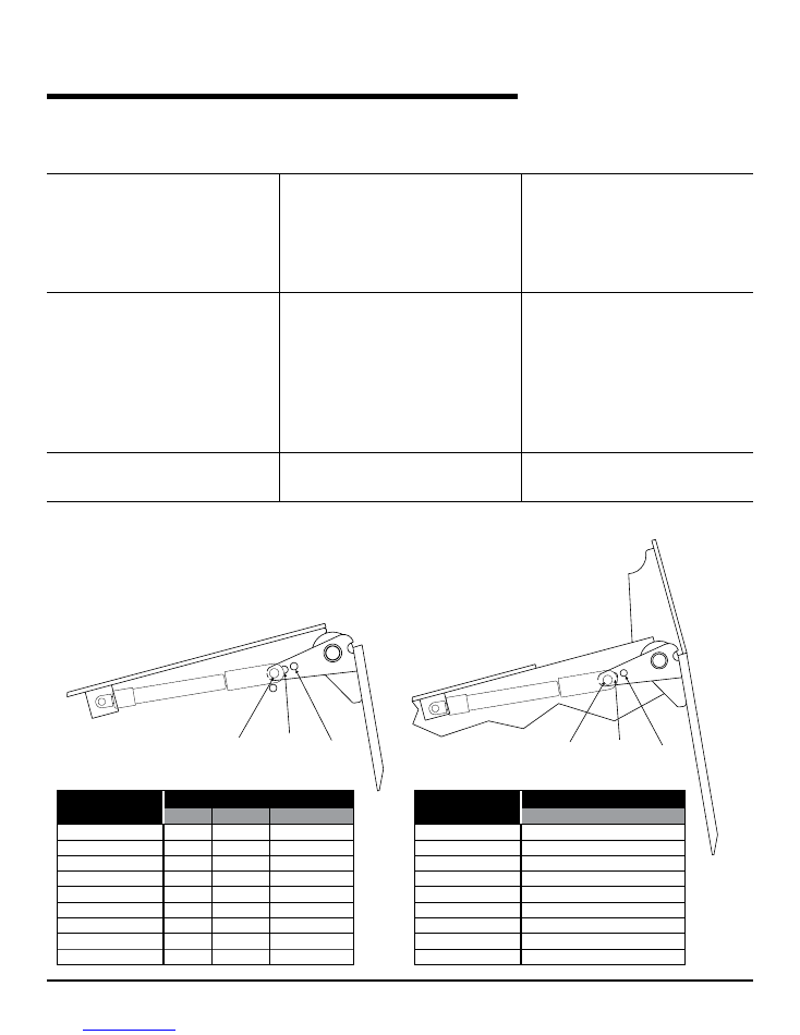
TroUbLeSHooTing,
continued
1
2
3
Lip Size
Lip Capacity
25K
30K & 35K 40K, 45K, & 50K
6'-16"
Hole 3
Hole 2
Hole 1
6'-18"
Hole 2
Hole 1
Hole 1
6'-20"
Hole 1
Hole 1
Hole 1
6-1/2'-16"
Hole 2
Hole 1
Hole 1
6-1/2'-18"
Hole 1
Hole 1
Hole 1
6-1/2'-20"
Hole 1
Hole 1
Hole 1
7'-16"
Hole 2
Hole 1
Hole 1
7'-18"
Hole 1
Hole 1
Hole 1
7'-20"
Hole 1
Hole 1
Hole 1
Lip Size
Hole
ALL CAPACITY
6'-16"
Hole 3
6'-18"
Hole 2
6'-20"
Hole 1
6-1/2'-16"
Hole 3
6-1/2'-18"
Hole 2
6-1/2'-20"
Hole 1
7'-16"
Hole 3
7'-18"
Hole 2
7'-20"
Hole 1
aFX Model
aFX-S Model
1
2
3
probLeM
poSSibLe caUSe
SoLUTion
3) Lip fails to lower to the stored position
when the dock leveler is raised from
vehicle
a) Check to make sure that the lip
extension mechanism is not bent or
binding. Be sure all parts are lubricated
properly. Lubricate as required. See Fig.
30.
b) Make sure pin is in correct position and
both pins are in good condition. See
Fig. 36
4) Dock level support legs will not retract
for below dock operation
5) Air bag is not lifting when the ramp is on
the maintenance post.
a) Check connection of dock level control
chain to the dock level support legs.
See Fig. 37.
b) Check for binding of dock level control
chain.
c) Check for binding in dock level support
legs.
d) Check length of below dock control
chain. Adjust chain so dock level
support legs are retracted the same
distance.
a) Connect the lifting kit chain using a link
closer to the spring. See chart on page
34.
a) Lip extension mechanism is bent or
binding.
b) Lip assist gas spring pin is in incorrect
position.
a) Chain not connected
b) Chain binding.
c) Legs binding.
d) Chain pulling one leg.
a) The link selected for attachment to the
deck is incorrect.
Fig. 36
©2012 4Front Engineered Solutions, Inc.
August 2012
6004751K — aFX
®
and aFX-S Dock Leveler — Safe
T
Frame
®
27
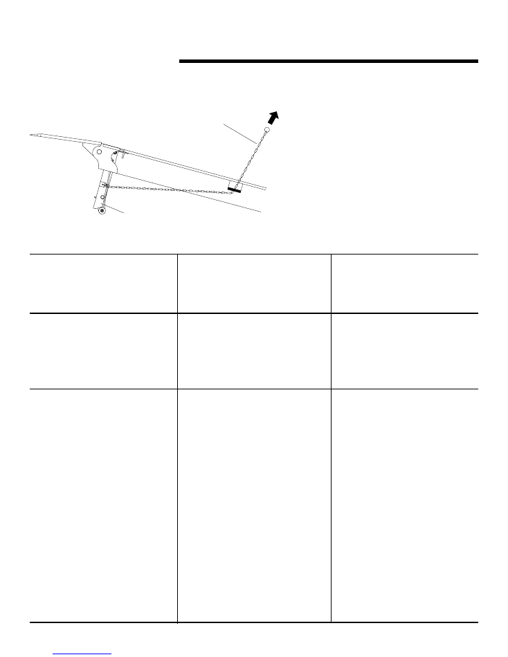
TroUbLeSHooTing,
continued
Dock Level
Support Leg
BDC
Chain
probLeM
poSSibLe caUSe
SoLUTion
6) Dock level support legs will not swing
fully forward
a) Check for binding or debris which may
be restricting leg.
b) Check below dock control chains to
assure chain has enough slack to allow
leg to swing forward. Adjust as required.
See Fig. 37.
7) Lip fails to extend
a) Check to make sure that the lip
extension mechanism is not bent or
binding. Be sure all parts are lubricated
properly. Lubricate as required. See Fig.
30.
b) Make sure all pins and pin retrainers are
in place and in good condition.
8) Lip extends but fails to stay in extended
position
a) Check to see that the lip extension
mechanism center bolt is straight and
free to rotate. See Fig. 35.
b) Check to see that the lip extends
far enough to allow the links and
connecting rod to align and then reach
an “over center” position.
a) Leg is binding.
b) Chain does not allow enough slack.
a) Lip extension mechanism is bent or
binding.
b) Pins are in incorrect position.
a) Lip extension mechanism center bolt is
bent or binding.
b) Links and connecting rod are not
aligned.
Fig. 37
©2012 4Front Engineered Solutions, Inc.
28
6004751K — aFX
®
and aFX-S Dock Leveler — Safe
T
Frame
®
August 2012
parTS LiST
1. To determine the correct replacement parts to order for
your adjustable dock leveler, you will need to know its
model number, serial number and capacity.
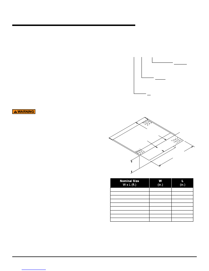
2. The model number and capacity can be found on the
dock leveler product label located on the frame leg. See
Fig. 40 and 41. The meaning of each digit in the model
number is shown in Fig. 38.
example:
aFX 6' x 8'
aFX-S 6' x 8'
- 6' wide
- Safety Lip
- 8' long
- 6' wide
- 8' long
3. To determine the nominal size of your dock leveler, see
Fig. 39.
To ensure proper function, durability and safety of the
product, only replacement parts that do not interfere with
the safe, normal operation of the product must be used.
Incorporation of replacement parts or modifications that
weaken the structural integrity of the product, or in any
way alter the product from its normal working condition
at the time of purchase from Kelley
®
could result in
product malfunction, breakdown, premature wear, death
or serious injury.
Fig. 38
aFX_ _ x _
Length
6 = 6' long
8 = 8' long
10 = 10' long
Width
6 = 6' wide
6.5 = 6-1/2' wide
7 = 7' wide
-S
Optional Safety Lip
Fig. 39
6 x 6
72
63
6 x 8
72
87
6 x 10
72
111
6.5 x 6
78
63
6.5 x 8
78
87
6.5 x 10
78
111
7 x 6
83
63
7 x 8
83
87
7 x 10
83
111
W
L
Pit depth
20" or 24"
Lip length
16", 18", Or 20"
©2012 4Front Engineered Solutions, Inc.
August 2012
6004751K — aFX
®
and aFX-S Dock Leveler — Safe
T
Frame
®
29
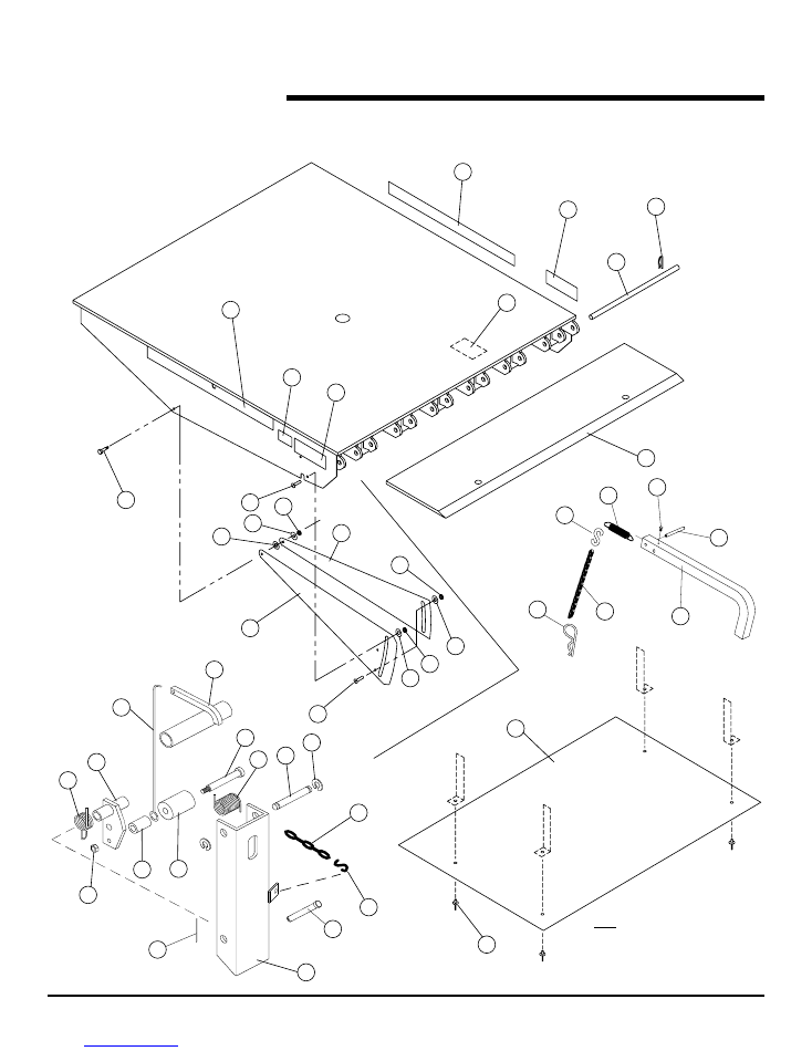
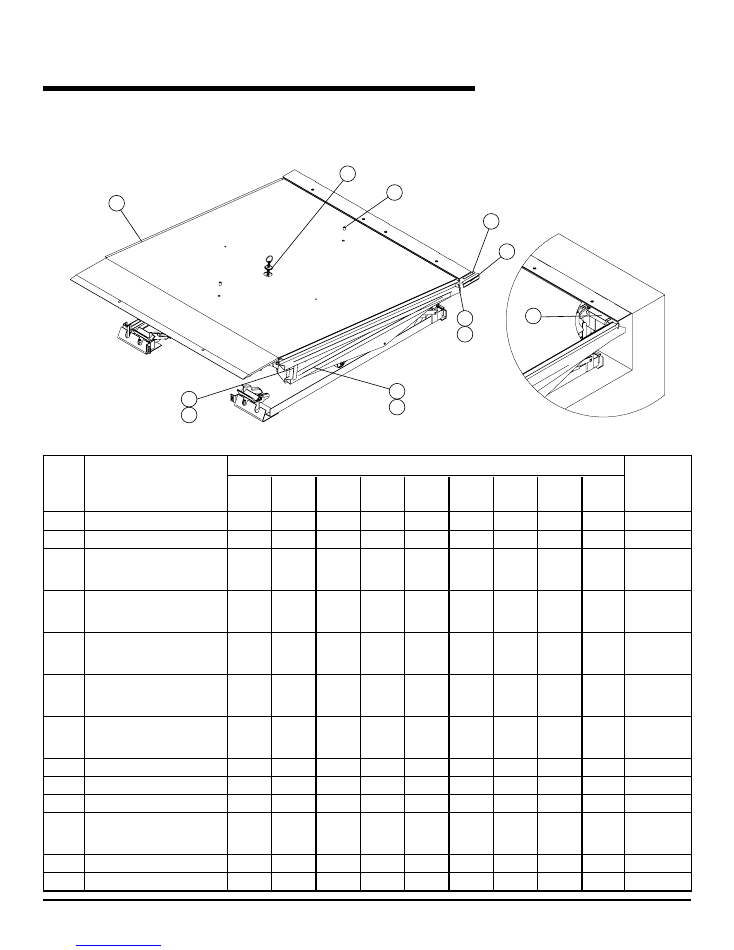
parTS LiST – aFX DocK LeVeLer
Ramp, Lip, Toe Guards and Lip Lock Assemblies
Fig. 40
20
2
3
17
16
16
6
5
23
4
9
39
Note: Rivets (Item 40)
Attach Bag Shield (Item 39)
To Brackets Welded On
Bottom Of Ramp.
40
15
15
21
7
7
8
8
10
10
22
28
11
12
13
14
27
25
24
42
30
41
31
18
35
37
36
33
32
34
24
38
26
29
©2012 4Front Engineered Solutions, Inc.
30
6004751K — aFX
®
and aFX-S Dock Leveler — Safe
T
Frame
®
August 2012
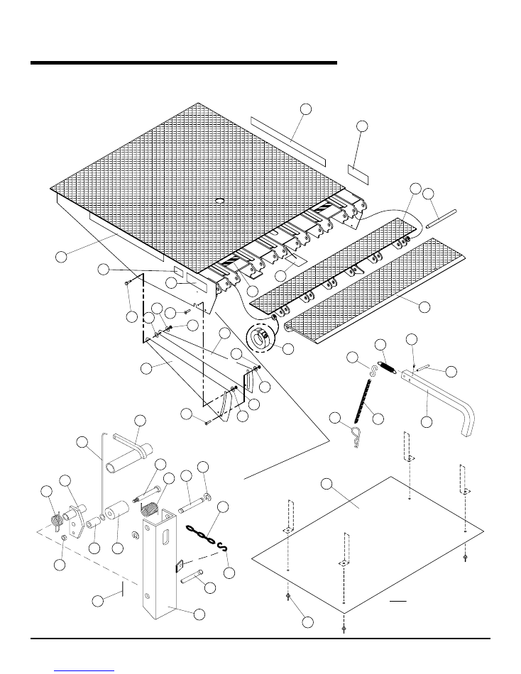
Fig. 41
2
3
4
15
1
17
19
7
6
5
7
8
8
10
10
11
12
13
14
15
39
40
20
23
9
21
22
28
26
29
27
25
24
30
41
31
18
42
Note: Rivets (Item 41)
Attach Bag Shield (Item 40)
to Brackets Welded on
Bottom of Ramp.
35
37
36
33
32
34
24
16
16
38
parTS LiST – aFX-S DocK LeVeLer
Ramp, Lip, Toe Guards and Lip Lock Assemblies
©2012 4Front Engineered Solutions, Inc.
August 2012
6004751K — aFX
®
and aFX-S Dock Leveler — Safe
T
Frame
®
31
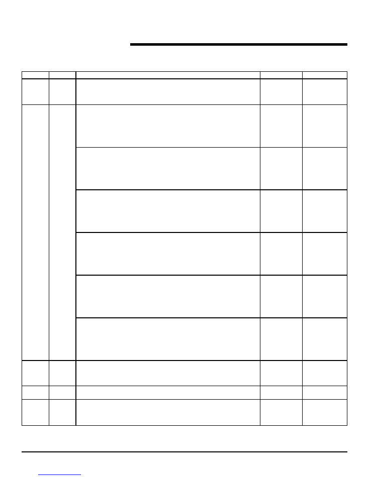
1
1
GUARD, SAFETY LIP
6' W. DOCK LEVELER
–
714-220
6-1/2' W. DOCK LEVELER
–
714-219
7' W. DOCK LEVELER
–
714-218
2
1
LIP, 6FT WIDE, 30K AND 35K CAPACITY
16" X 6' W. 4° BEND
711-858
–
16" X 6' W. 7° BEND
711-857
–
18" X 6' W. 4° BEND
711-860
–
18" X 6' W. 7° BEND
711-859
–
20" X 6' W. 4° BEND
711-862
–
20" X 6' W. 7° BEND
711-861
–
LIP, 6-1/2' WIDE, 30K AND 35K CAPACITY
16" X 6.5' W. 4° BEND
711-876
–
16" X 6.5' W. 7° BEND
711-875
–
18" X 6.5' W. 4° BEND
711-878
–
18" X 6.5' W. 7° BEND
711-877
–
20" X 6.5' W. 4° BEND
711-880
–
20" X 6.5' W. 7° BEND
711-879
–
LIP, 7' WIDE, 30K AND 35K CAPACITY
16" X 7' W. 4° BEND
711-894
–
16" X 7' W. 7° BEND
711-893
–
18" X 7' W. 4° BEND
711-896
–
18" X 7' W. 7° BEND
711-895
–
20" X 7' W. 4° BEND
711-898
–
20” X 7' W. 7° BEND
711-897
–
LIP, 6FT WIDE, 40K, 45K AND 50K CAPACITY
16" X 6' W. 4° BEND
711-864
711-864
16" X 6' W. 7° BEND
711-863
711-863
18" X 6' W. 4° BEND
711-866
711-866
18" X 6' W. 7° BEND
711-865
711-865
20" X 6' W. 4° BEND
711-868
711-868
20" X 6' W. 7° BEND
711-867
711-867
LIP, 6-1/2' WIDE, 40K, 45K AND 50K CAPACITY
16" X 6.5' W. 4° BEND
711-882
711-882
16" X 6.5' W. 7° BEND
711-881
711-881
18" X 6.5' W. 4° BEND
711-884
711-884
18" X 6.5' W. 7° BEND
711-883
711-883
20" X 6.5' W. 4° BEND
711-886
711-886
20" X 6.5' W. 7° BEND
711-885
711-885
LIP, 7' WIDE, 40K, 45K AND 50K CAPACITY
16" X 7' W. 4° BEND
711-900
711-900
16" X 7' W. 7° BEND
711-899
711-899
18" X 7' W. 4° BEND
711-902
711-902
18" X 7' W. 7° BEND
711-901
711-901
20" X 7' W. 4° BEND
711-904
711-904
20" X 7' W. 7° BEND
711-903
711-903
3
2
LIP ShAFT
6' W. DOCK LEVELER
712-957
713-786
6.5' W. DOCK LEVELER
712-958
713-787
7' W. DOCK LEVELER
712-959
713-788
4
2
RETAINER, ShAFT - hINGE PIN
035-451
–
2
COLLAR, ShAFT - hINGE PIN
–
131-542
5
2
TOE GUARD, MIDDLE SLIDING
6' LG. DOCK LEVELER
155-554
155-554
8' LG. DOCK LEVELER
155-555
155-555
10' LG. DOCK LEVELER
155-557
155-557
iTeM
QTy
parT DeScripTion
aFX
aFX-S
parTS LiST,
continued
Ramp, Lip, Toe Guards and Lip Lock Assemblies
©2012 4Front Engineered Solutions, Inc.
32
6004751K — aFX
®
and aFX-S Dock Leveler — Safe
T
Frame
®
August 2012
6
2
TOE GUARD, BOTTOM SLIDING
6' LG. DOCK LEVELER
155-554
155-554
8' LG. DOCK LEVELER
155-556
155-556
10' LG. DOCK LEVELER
155-557
155-557
7
4
NUT, LOCK, 3/8-16
000-253
000-253
8
4
SCREW, TRUSS hEAD 3/8-16 X 1
131-477
131-477
9
2
ROLLER LIFTER, WIRE FORM
101-100
101-100
10
4
SPACER, TOE GUARD
152-878
152-878
11
2
SCREW, ShOULDER
131-455
131-455
12
2
WAShER, 3/8" FLAT
000-214
000-214
13
2
WAShER, 5/16" FLAT
000-055
000-055
14
2
NUT, 5/16-18 NYLOC
131-456
131-456
15
2
LABEL, hAzARD
138-837
138-837
16
2
LABEL, WARNING
6008485
6008485
17
1
LABEL, LIP LOCK
700-136
700-136
18
2
SPACER, PLASTIC PIPE
6001402
6001402
19
4
LABEL, SAFETY STRIPE
–
6008554
20
SUPPORT, DOCK LEVEL
1
LEFT SIDE (ShOWN)
714-126
714-126
1
RIGhT SIDE (NOT ShOWN)
714-125
714-125
21
2
SPRING, TORSION
030-195
030-195
22
2
PIN, GROOVED
035-338
035-338
23
4
KLIPRING
049-060
049-060
24
3
“S” - hOOK
000-181
000-181
25
2
NUT, LOCK 3/8-16
000-030
000-030
26
2
PIN, CLEVIS 5/8" X 3-1/2" LG.
6001348
6001348
27
2
SPRING, TORSION
101-091
101-091
28
2
WELDMENT, ROLLER ARM
714-070
714-070
29
2
PIN, COTTER 1/8" X 1-1/4"
035-036
035-036
30
2
ShOULDER SCREW 1/2 X 4
6001340
6001340
31
2
ROLLER, CAM FOLLOWER
6001341
6001341
32
1
LEVER, LIP LOCK
155-150
155-150
33
1
SPRING, EXTENSION
700-135
700-135
34
1
PIN, ROLL 3/16" DIA. X 2"
035-149
035-149
35
1
6" LG SASh ChAIN
6001950
6001950
36
1
PIN, COTTER - hAIR
035-200
035-200
37
1
SCREW, DRIVE #6 X 1/4" LG.
000-518
000-518
38
1
DECAL, AFX
138-871
138-871
39
1
BAG ShIELD
6' LG. DOCK LEVELER - ALL CAPACITY
155-295
155-295
8' LG. DOCK LEVELER - 30K - 45K CAPACITY
155-295
155-400
8' LG. DOCK LEVELER - 50K CAPACITY
155-400
155-400
10' LG. DOCK LEVELER - ALL CAPACITY
155-400
155-400
40
4
RIVET, POP 3/16 DIA.
131-271
131-271
41
LIFTER, ROLLER ARM
1
LEFT hAND
714-084
714-084
1
RIGhT hAND
714-083
714-083
42
1
BELOW DOCK CONTROL ChAIN ASSEMBLY — 6'
6012661
6012661
BELOW DOCK CONTROL ChAIN ASSEMBLY — 8'
6003453
6003453
BELOW DOCK CONTROL ChAIN ASSEMBLY — 10' 6003452
6003452
6003452
iTeM
QTy
parT DeScripTion
aFX
aFX-S
parTS LiST,
continued
Ramp, Lip, Toe Guards and Lip Lock Assemblies
©2012 4Front Engineered Solutions, Inc.
August 2012
6004751K — aFX
®
and aFX-S Dock Leveler — Safe
T
Frame
®
33
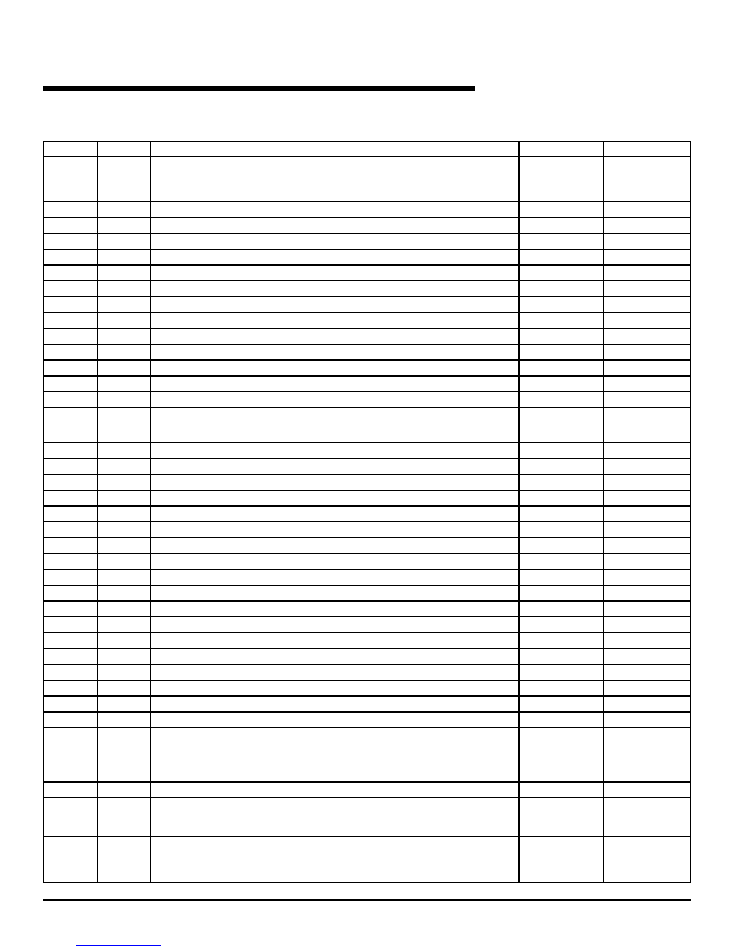
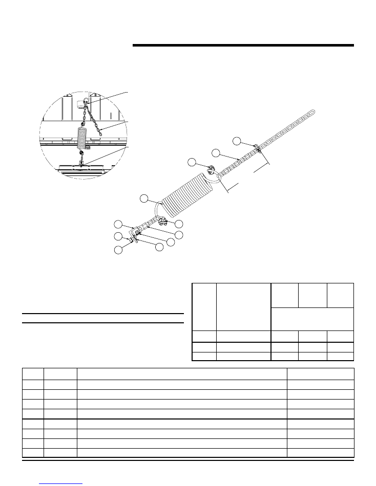
Fig. 42
parTS LiST
Clean pit kit
item Quantity Description
part number
1
2
ChAIN ShACKLE-1/4"
442800
2
1
LIP ASSIST SPRING
333043
3
18
3-16 LINK ChAIN
131102
4
2
CABLE CLAMP
441103
5
1
AIR BAG LIFTING KIT ANGLE
6008139
6
2
FLAT WAShER
234091
7
1
UPSET ThREAD NUT
000-030
8
1
TRUSS hD MACh SCR 3/8-16 X 1"
000357
24" pit 24" pit
20" pit with 4" w/out 4"
wheel riser kit wheel riser kit
number of links
position Leveler Size
from spring to
shackle
1
8' 50K
8
8
12
2
6', all capacities
10
10
14
3
10' (all capacities)
15
15
18
noTe:
The position of the shackle may vary depending on spring
tension and chain link size. Positions are for reference and
can be adjusted as necessary. Proper installation will lift the
bag rollers approximately 8" off the pit floor when the deck
is stored.
1
3
4
2
5
7
6
8
1
3
4
The mounting angle is connected
to the center air bag support pan.
Excess chain can hang
free or be cut off
The upper shackle is connected to
the ring next to the chain cup.
Link location
(see chart)
8' 50k levelers do not use
the same location as lower
capacity units. Incorrect
positioning will result in
damage to the spring.
©2012 4Front Engineered Solutions, Inc.
34
6004751K — aFX
®
and aFX-S Dock Leveler — Safe
T
Frame
®
August 2012
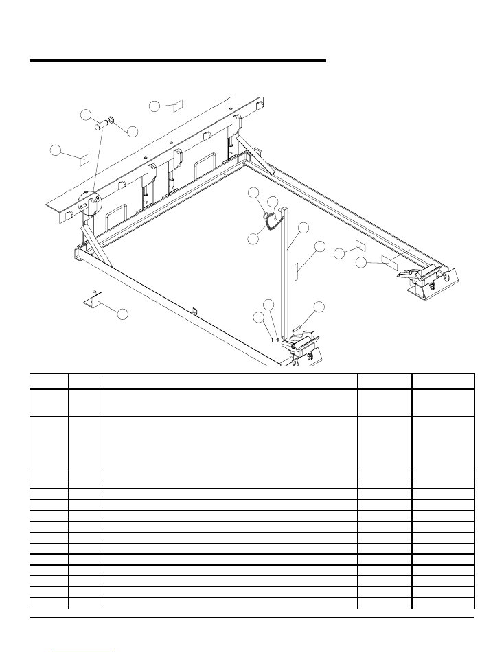
parTS LiST,
continued
Subframe and Maintenance Strut Assemblies
10
11
2
3
6
7
5
12
4
8
9
13
14
12
15
Fig. 43
Note: Items 5 - 8 included in item 2.
iTeM
QTy
parT DeScripTion
aFX
aFX-S
1
1
DOCUMENTATION KIT (NOT ShOWN)
6001953
6001953
MANUAL
6004751
6004751
PLACARD, WARNING AND INSTRUCTIONS
6001952
6001952
2
1
MAINTENANCE STRUT ASSEMBLY
6' LG. DECK IN 20" PIT
710-042
710-042
6' LG. DECK IN 24" PIT
6013620
6013620
8' LG. DECK IN 20" PIT
708-883
708-883
8' LG. DECK IN 24" PIT
6013621
6013621
10' LG. DECK IN 24" PIT
712-537
712-537
3
4
PIN, hINGE
6004128
6004128
4
4
CLIP RING - 3/4"
236-110
236-110
*5
1
SCREW, DRIVE
000-518
000-518
*6
1
PIN, COTTER - hAIR
035-200
035-200
*7
1
ChAIN, SASh
032-195
032-195
*8
1
DECAL, MAINT. STRUT
921-074
921-074
9
1
WAShER, FLAT 3/8
000-214
000-214
10
1
PIN, COTTER
035-036
035-036
11
1
PIN, CLEVIS
035-051
035-051
12
2
DECAL, FORK LOCATION
921146
921146
13
4
FOOT ASSEMBLY
6002915
6002915
14
1
DANGER LABEL - ENTERING PIT
921-070
921-070
15
1
SERIAL TAG
6009761
6009761
©2012 4Front Engineered Solutions, Inc.
August 2012
6004751K — aFX
®
and aFX-S Dock Leveler — Safe
T
Frame
®
35
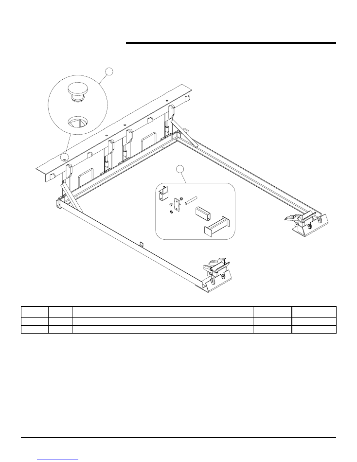
parTS LiST,
continued
Optional Subframe Riser Kit and Cap Plug
iTeM
QTy
parT DeScripTion
aFX
aFX-S
1
1
RISER KIT (FIELD INSTALLED)
6004652
6004652
2
1
REAR ANGLE CAP PLUG
6004487
6004487
1
2
4x
4x
2x
2x
2x
6x
6x
6x
Fig. 44
©2012 4Front Engineered Solutions, Inc.
36
6004751K — aFX
®
and aFX-S Dock Leveler — Safe
T
Frame
®
August 2012
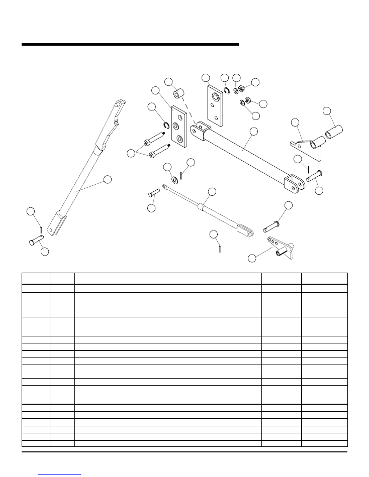
parTS LiST,
continued
Connecting Rod, Push Bar and Lip Assist Assemblies
Fig. 45
5
8
16
13
12
6
1
7
1
15
3
8
5
11
8
8
9
6
1
14
10
2
10
5
4
15
10
iTeM
QTy
parT DeScripTion
aFX
aFX-S
1
1
PUSh BAR
6011490
6011490
2
1
ROD, CONNECTING
6' LG. DOCK LEVELER
711-848
711-848
8' LG. DOCK LEVELER
711-849
711-849
10' LG. DOCK LEVELER
712-462
712-462
3
1
LEVER, LIP LIFTER
6' LG. DOCK LEVELER
711-998
711-998
8' AND 10' LG. DOCK LEVELER
711-999
711-999
4
1
LEVER, LIP ASSIST
155-811
155-811
5
3
PIN, CLEVIS 1/2" DIA. X 1-3/4"
035-010
035-010
6
1
PIN, CLEVIS 3/8" DIA. X 2"
035-150
035-150
8
4
PIN, COTTER 1/8" DIA. X 1-1/4"
035-036
035-036
9
1
GAS SPRING (25K LEVELERS)
6002469
6002469
1
GAS SPRING (30-45K LEVELERS)
709-437
709-437
10
3
WAShER, 3/8"
000-214
000-214
11
1
SPACER, LIP
6-1/2' WIDE DOCK LEVELER
287-606
287-606
7' WIDE DOCK LEVELER
287-607
287-607
12
1
LINK, Rh
712-001
712-001
13
1
LINK, Lh
712-002
712-002
14
2
BOLT, SOC. hD. ShLD.
712-061
712-061
15
2
NUT, hEX 3/8-16
000-030
000-030
16
2
KLIPRING 5/8"
049-060
049-060
17
1
ROLLER
700-045
700-045
©2012 4Front Engineered Solutions, Inc.
August 2012
6004751K — aFX
®
and aFX-S Dock Leveler — Safe
T
Frame
®
37
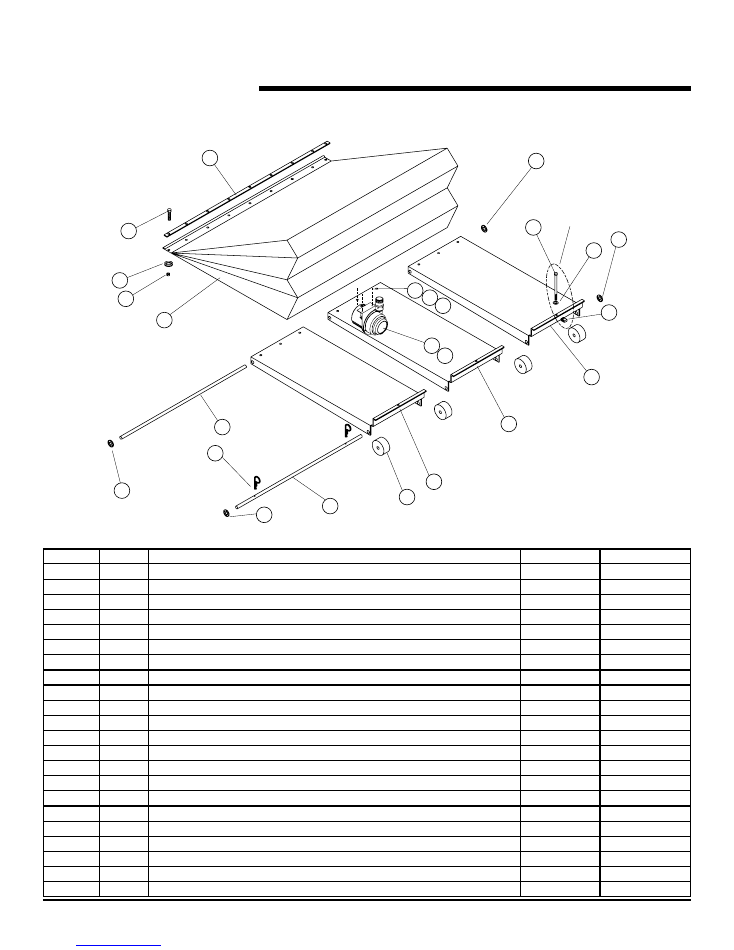
parTS LiST,
continued
Air Bag/Pan Assembly
Fig. 46
3
8
9
10
7
4
16
20
19
18
17
4
12
13
14
5
FOR
SHIPPING
ONLY
11
2
15
15
1
6
15
15
iTeM
QTy
parT DeScripTion
aFX
aFX-S
1
BAG/PAN/FAN ASSEMBLY (INCLUDES ITEMS 1-20)
714-129
714-129
1
9
WAShER, 3/8" FLAT
000-051
000-051
2
1
LIFTING BAG
714-128
714-128
3
1
CLAMP BAR
157-747
157-747
4
2
PAN, OUTER
156-352
156-352
5
1
PAN, INNER
156-350
156-350
6
9
NUT, NYLOK, 3/8-16
000-253
000-253
7
4
WhEEL
711-846
711-846
8
1
AXLE, FRONT
712-745
712-745
9
1
AXLE, REAR
712-812
712-812
10
2
PIN, COTTER, hAIR
035-200
035-200
11
9
BOLT, hEX hD. 3/8-16 X 1-1/4"
000-357
000-357
12
2
BOLT, 3/8-16 X 7"
131-434
131-434
13
2
WAShER, FLAT 3/8
000-214
000-214
14
2
NUT, RETAINER
131-432
131-432
15
4
RING, RETAINING
131-457
131-457
16
1
FAN MOTOR ASSY – 120V
6008662
6008662
17
2
NUT, hEX LOCK 1/4-20
000-315
000-315
18
2
WAShER, FLAT, 1/4"
131-485
131-485
19
2
SCREW, BUTTON FLG. hD 1/4-20 X 3/4"
131-483
131-483
20
1
NIPPLE
155-578
155-578
N/S
A/R
PATCh KIT, BAG (NOT ShOWN)
184-379
184-379
6' Lg DocK LeVeLerS – aLL capaciTy
©2012 4Front Engineered Solutions, Inc.
38
6004751K — aFX
®
and aFX-S Dock Leveler — Safe
T
Frame
®
August 2012
iTeM
QTy
parT DeScripTion
aFX
aFX-S
1
BAG/PAN/FAN ASSEMBLY (INCLUDES ITEMS 1-20)
712-805
712-807
1
LIFTING BAG ASSEMBLY (INCLUDES ITEMS 2,3,6 AND 11)
184-442
184-441
1
9
WAShER, 3/8" FLAT
000-051
000-051
2
1
LIFTING BAG
713-150
713-151
3
1
CLAMP BAR
157-747
157-747
4
2
PAN, OUTER
155-579
155-649
5
1
PAN, INNER
155-580
155-650
6
9
NUT, NYLOK, 3/8-16
000-253
000-253
7
4
WhEEL
711-846
711-846
8
1
AXLE, FRONT
712-745
711-845
9
1
AXLE, REAR
712-812
712-812
10
2
PIN, COTTER, hAIR
035-200
035-200
11
9
BOLT, hEX hD. 3/8-16 X 1-1/4"
000-357
000-357
12
2
BOLT, 3/8-16 X 7"
131-434
131-434
13
2
WAShER, FLAT 3/8
000-214
000-214
14
2
NUT, RETAINER
131-432
131-432
15
4
RING, RETAINING
131-457
131-457
16
1
FAN MOTOR ASSY – 115V
6008662
6008662
17
2
NUT, hEX LOCK 1/4-20
000-315
000-315
18
2
WAShER, FLAT, 1/4"
131-485
131-485
19
2
SCREW, BUTTON FLG. hD 1/4-20 X 3/4"
131-483
131-483
20
1
NIPPLE
155-578
155-578
A/R
PATCh KIT, BAG (NOT ShOWN)
184-379
184-379
8' Lg DocK LeVeLerS – 30K, 35K, 40K, and 45K capaciTy (aFX MoDeL only)
8' Lg DocK LeVeLerS – 40K, and 45K capaciTy (aFX-S MoDeL only)
iTeM
QTy
parT DeScripTion
aFX
aFX-S
1
BAG/PAN/FAN ASSEMBLY (INCLUDES ITEMS 1-20)
712-807
712-807
1
LIFTING BAG ASSEMBLY (INCLUDES ITEMS 2,3,6 AND 11)
184-441
184-441
1
9
WAShER, 3/8" FLAT
000-051
000-051
2
1
LIFTING BAG
713-151
713-151
3
1
CLAMP BAR
157-747
157-747
4
2
PAN, OUTER
155-649
155-649
5
1
PAN, INNER
155-650
155-650
6
9
NUT, NYLOK, 3/8-16
000-253
000-253
7
6
WhEEL
711-846
711-846
8
1
AXLE, FRONT
711-845
711-845
9
1
AXLE, REAR
712-812
712-812
10
4
PIN, COTTER, hAIR
035-200
035-200
11
9
BOLT, hEX hD. 3/8-16 X 1-1/4"
000-357
000-357
12
2
BOLT, 3/8-16 X 7"
131-434
131-434
13
2
WAShER, FLAT 3/8
000-214
000-214
14
2
NUT, RETAINER
131-432
131-432
15
4
RING, RETAINING
131-457
131-457
16
1
FAN MOTOR ASSY – 115V
6008662
6008662
17
2
NUT, hEX LOCK 1/4-20
000-315
000-315
18
2
WAShER, FLAT, 1/4"
131-485
131-485
19
2
SCREW, BUTTON FLG. hD 1/4-20 X 3/4"
131-483
131-483
20
1
NIPPLE
155-578
155-578
A/R
PATCh KIT, BAG (NOT ShOWN)
184-379
184-379
8' Lg DocK LeVeLerS – 50K capaciTy
10' Lg DocK LeVeLerS – aLL capaciTy
parTS LiST,
continued
Air Bag/Pan Assembly
©2012 4Front Engineered Solutions, Inc.
August 2012
6004751K — aFX
®
and aFX-S Dock Leveler — Safe
T
Frame
®
39
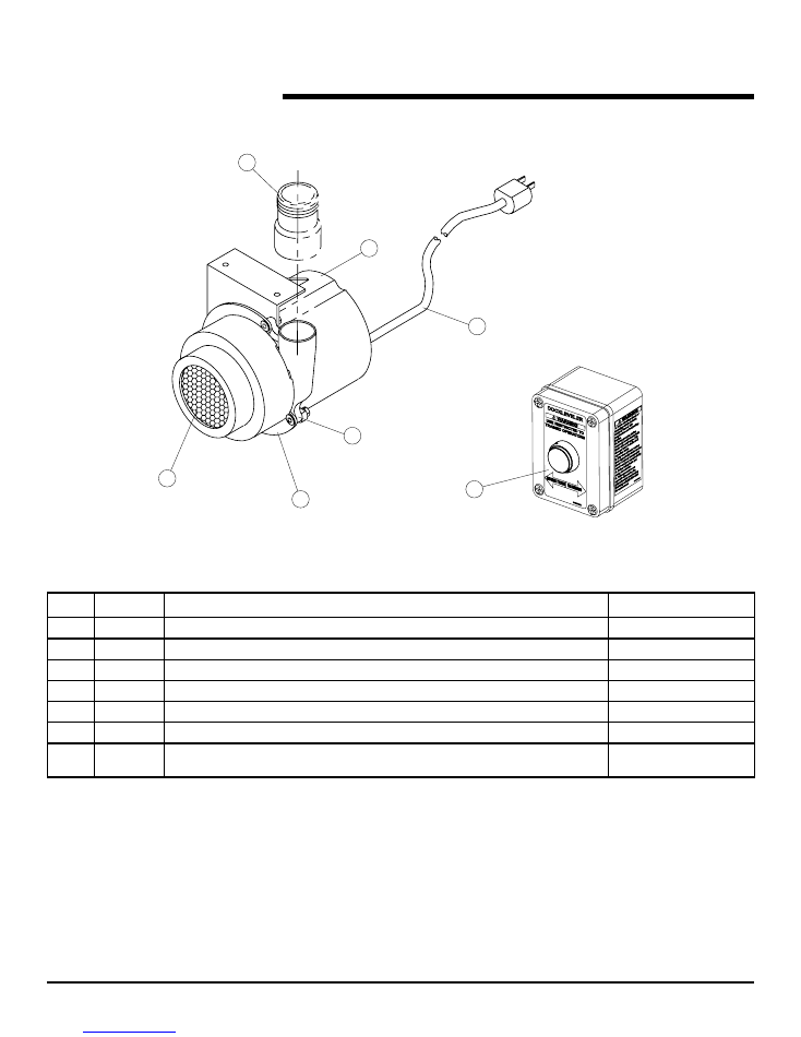
parTS LiST,
continued
Fan/Piping Assembly
Fig. 47
7
1
5
6
2
3
4
*
For use with interlock applications on STAR
®
4 and AUTO CHOCK
®
vehicle restraints.
item Quantity Description
part number
1
1
MOTOR, AIR 2 STAGE 120V
6008185
2
1
FILTER hOUSING
712-748
3
1
FILTER, FAN
712-196
4
1
NIPPLE
155-578
5
1
CORD W/PLUG
712-027
6
1
hOUSING, FAN
712-813
7
1
115V CONTROL STATION
908-753
CONTROL STATION (OPTIONAL DUAL CONTACT)*
909-052
©2012 4Front Engineered Solutions, Inc.
40
6004751K — aFX
®
and aFX-S Dock Leveler — Safe
T
Frame
®
August 2012
Fig. 48
parTS LiST,
continued
opTionaL energy gUarD
®
DocK LeVeLLer SeaLing SySTeM
item Description
Quantity
part
number
6x6 6.5x6 6x7
6x8 6.5x8 7x8 6x10 6.5x10 7x10
6008228 6008229 6008230 6008231 6008232 6008233 6008234 6008235 6008236
1
5-1/2" front seal
2
2
2
2
2
2
2
2
2
6008166
2
Vertical seal
2
2
2
2
2
2
2
2
2
6008173
3
6' upper seal
2
2
2
6008167
8' upper seal
2
2
2
6008169
10' upper seal
2
2
2
6008171
4
Aluminum strip 53-1/2"
2
2
2
6008175
Aluminum strip 77-1/2"
2
2
2
6008177
Aluminum strip 101-1/2"
2
2
2
6008179
5
6' Lower seal
2
2
2
6008168
8' Lower seal
2
2
2
6008170
10' Lower seal.
2
2
2
6008172
6
Aluminum strip 6' upper
2
2
2
6008174
Aluminum strip 8' upper
2
2
2
6008176
Aluminum strip 10' upper
2
2
2
6008178
7
6' Kelley rear seal
1
1
1
6007671
6.5' Kelley rear seal
1
1
1
6007672
7' Kelley rear seal
1
1
1
6007673
8
TEK screws (not shown)
26
26
26
26
26
26
28
28
28
215702
9
Chain cup seal
2
2
2
2
2
2
2
2
2
0392
10
3/4-10 Set screw
2
2
2
2
2
2
2
2
2
6008249
11
W/seal 600 W brush
2
2
2
2
2
2
328907
W/seal 800 W brush
2
2
2
328908
W/seal 600 W brush cut
2
2
2
328910
12
Corner bulb seal
2
2
2
2
2
2
2
2
2
6009507
13
Transition angle seal (optional)
2
2
2
2
2
2
2
2
2
6008247
11
9
10
12
3
4
5
6
1
2
13
7