Full Text Searchable PDF User Manual
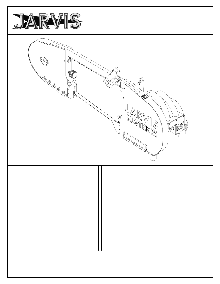
TABLE OF
CONTENTS
Page
. . . . . . . . . . . . . . . . . . . . . . . . .
Buster V Band Saw
460/230V--60Hz
4006033
. . . . . . . . . .
380/220V--50Hz
4006057
. . . . . . . . . .
Spring Balancer
4042052
. . . . . . . . . . . . . . . .
Air Balancer (4 feet overall length) 4042016
Air Balancer (20 feet overall length) 4042020
Standard Blade (127 in)
1023159
. . . . . . . . .
Cut Tooth Blade (127 in)
1023338
. . . . . . . .
JET Blade (127 in)
1023620
. . . . . . . . . . . . .
•
Safety Messages to Employer and
Safety Director
2
. . . . . . . . . . . . . . . . . . .
•
Safety Messages to Operators,
Maintenance and Cleanup Personnel 3
•
Parts Diagram and List
4
. . . . . . . . . . . .
•
Specifications
10
. . . . . . . . . . . . . . . . . . .
•
Installation Instructions
10
. . . . . . . . . . .
•
Operation Instructions
12
. . . . . . . . . . . .
•
Maintenance Instructions
13
. . . . . . . . .
•
Motor Wiring Diagrams
15
. . . . . . . . . . .
PRODUCTS CORPORATION
33 ANDERSON ROAD, MIDDLETOWN, CONNECTICUT 06457-4926
UNITED STATES OF AMERICA EMAIL.
jarvis.products.corp@snet.net
TEL. 860-347-7271 FAX. 860-347-6978 WWW
.jarvisproducts.com
Model Buster V
Beef Splitting Band Saw
EQUIPMENT
SELECTION
Ordering No.
. . . . . . . . . . . . .
®
JARVIS
6206002;::::
safety messages to employer
and safety director
Model Buster V
page 2 of 16
®
JARVIS
6206002;::::
PRODUCTS CORPORATION
33 ANDERSON ROAD, MIDDLETOWN, CONNECTICUT 06457-4926
UNITED STATES OF AMERICA EMAIL.
jarvis.products.corp@snet.net
TEL. 860-347-7271 FAX. 860-347-6978 WWW
.jarvisproducts.com
1. Remove
and
repair
any tool that malfunctions.
All
personnel must be instructed to remove any
malfunctioning equipment.
2. Ensure
that all employees who use this tool are trained in the proper use of this tool and are aware of
the dangers that may arise if they do not follow the procedure outlined in this brochure.
3. Enclosed
are four (4) copies of
“NOTICE TO OPERATORS, MAINTENANCE AND CLEANUP
PERSONNEL.”
Post one copy on the employees’ bulletin board; give one copy to the operator(s);
give one copy to the maintenance foreman; and give one copy to the sub-contract cleanup / internal
cleanup foreman.
Additional copies will be provided upon request.
4.
The tool is designed and intended to be powerful. This fact should be obvious to your employees, but
you must emphasize it to them.
5. Never
make modifications or alterations to the tool.
Replace any missing or illegible labels.
6. Ensure
that proper procedures are established in accordance with OSHA’s lockout/tagout procedures
(29 CFR 1910.147) to prevent accidental startup or release of stored energy.
7. Follow
our installation and maintenance instructions for proper installation and care of the tool.
8. Avoid
injury. Do not permit the tool to be misused.
9. If
you
resell
or
distribute
a Jarvis product, you must provide the purchaser with the appropriate safety
sheets and tool brochure.
Additional copies of safety sheets and tool brochures will be provided upon
request.
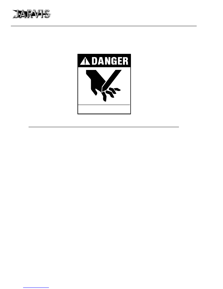
SAFETY MESSAGES TO EMPLOYER AND SAFETY DIRECTOR
AVOID INJURY
Keep hands clear.
safety messages to operators,
maintenance and cleanup personnel
Model Buster V
page 3 of 16
®
JARVIS
6206002;::::
PRODUCTS CORPORATION
33 ANDERSON ROAD, MIDDLETOWN, CONNECTICUT 06457-4926
UNITED STATES OF AMERICA EMAIL.
jarvis.products.corp@snet.net
TEL. 860-347-7271 FAX. 860-347-6978 WWW
.jarvisproducts.com
1. Disconnect
the power supply in accordance with OSHA’s lockout/tagout procedures (29 CFR
1910.147) before making any blade changes.
2. Disconnect
the power supply in accordance with OSHA’s lockout/tagout procedures (29 CFR
1910.147) before performing any repairs or maintenance.
3. Disconnect
the power supply -- or have the power supply disconnected -- in accordance with OSHA’s
lockout/tagout procedures (29 CFR 1910.147) before performing any cleanup.
4. Disconnect
the power supply when the tool is not in use.
5. Never
put fingers, hands or other parts of the body on the cutting edge or within the cutting path of the
tool when it is connected to the power supply.
6. Test
the tool prior to use or daily.
Depress
each trigger separately and the tool should not start.
Depress
one trigger, then pause one second and depress the other trigger and the tool should not start.
Repeat
this procedure reversing the triggers.
Depress
both triggers simultaneously and the tool should start.
With the tool running, release one trigger and the tool should stop.
Continue
holding the depressed
trigger and then depress the other trigger. The tool should not start.
Repeat
this procedure holding the
other trigger.
If the tool malfunctions, remove it from service and report or repair it immediately.
7. Never
depress the triggers unless you want to use or test the tool.
8. Never
make modifications or alterations to the tool.
Report or replace any missing or illegible labels.
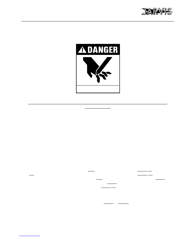
SAFETY MESSAGES TO OPERATORS, MAINTENANCE AND CLEANUP
PERSONNEL
REMOVE ANY MALFUNCTIONING TOOL FROM SERVICE
REPORT ANY PROBLEMS TO YOUR SUPERVISOR
Keep hands clear.
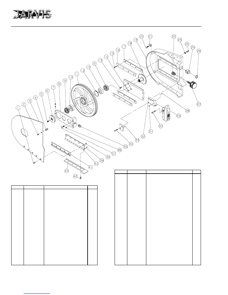
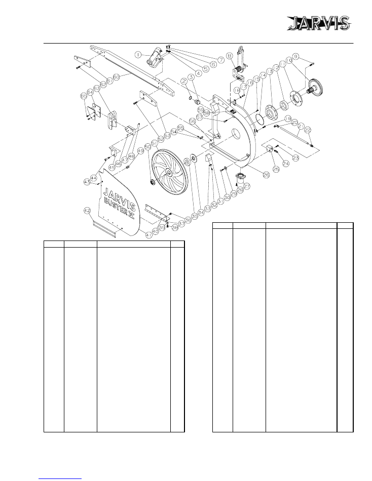
parts diagram and list
Model Buster V
page 4 of 16
®
JARVIS
6206002;::::
PRODUCTS CORPORATION
33 ANDERSON ROAD, MIDDLETOWN, CONNECTICUT 06457-4926
UNITED STATES OF AMERICA EMAIL.
jarvis.products.corp@snet.net
TEL. 860-347-7271 FAX. 860-347-6978 WWW
.jarvisproducts.com
ITEM
PART NO.
PART NAME
QTY
ITEM
PART NO.
PART NAME
QTY
1
1055338
Flat Head Socket Screw
5
2
1055277
Flat Head Socket Screw
1
3
1002227
Idler Wheel Cover
1
4
1061201
Door Catch
1
5
1038011
Grease Fitting
1
6
1007176
Lock Nut
1
7
1055536
Socket Head Cap Screw
1
8
1042127
Support Bracket with item 7
1
9
1021235
Roller Bearing Cone
2
10
1021234
Roller Bearing Cup
2
3021006
Bearing Cup and Cone
11
1057023
Idler Wheel
1
12
1013141
Internal Retaining Ring
1
13
1055363
Flat Head Socket Screw
4
14
1042126
Slide Plate
1
15
1055021
Socket Head Cap Screw
8
16
1061220
Slide Rail
2
17
1029194
Slide Rail Spacer
2
18
1020146
Idler Wheel Shaft
1
19
1016243
Idler End Housing
1
20
1055862
Flat Head Screw
2
21
1004275
Washer
2
22
1060030
Hex Head Threaded Insert
1
23
1004154
Plain Washer
6
24
1055488* Hex Head Screw
6
25
1006025
Door Knob
1
26
1013122
Internal Retaining Ring
1
27
page 6
Torque Knob Assembly
1
28
1010579
Roll Pin
2
29
page 6
Guide Assembly, Idler End
1
30
1055457
Socket Hd Shoulder Screw
2
31
1036127
Bushing (spare part only)
1
32
1032155
Guide Mounting Plate
1
33
1002224
Guide Plate Cover
1
34
1055270
Socket Head Cap Screw
2
35
1036103
Torque Knob Thrust Bushing
1
36
1055026
Socket Set Screw, Cup Pt.
1
37
1055486
Hex Head Screw
2
38
1007177
Taper Nut
5
39
1067008
Hinge with item 40
1
40
1010214
Hinge Pin
1
41
1029195
Hinge Spacer
1
42
1055361
Flat Head Socket Screw
4
43
1002221
Hinge Cover
1
IDLER END
Figure A
*
* Tighten to 37 lbf--ft
** Use grease gun 8038001
**
parts diagram and list
Model Buster V
page 5 of 16
®
JARVIS
6206002;::::
PRODUCTS CORPORATION
33 ANDERSON ROAD, MIDDLETOWN, CONNECTICUT 06457-4926
UNITED STATES OF AMERICA EMAIL.
jarvis.products.corp@snet.net
TEL. 860-347-7271 FAX. 860-347-6978 WWW
.jarvisproducts.com
1
page 7 or 8 Top Handle Assembly
1
2
1013122
Internal Retaining Ring
1
3
1006025
Door Knob
1
4
1004051
Int. Tooth Lock Washer
1
5
1004093
Int. Tooth Lock Washer
1
6
1055304
Hex Head Screw
1
7
1055358
Hex Head Screw
1
8
page 7
Hanger Assembly
1
9
1055027
Socket Head Cap Screw
4
10
1026090
Driven Gear 60 Hz 92 teeth
1
1026078
Driven Gear 50 Hz 86 teeth
1
11
1002213
Bearing Retaining Cover
1
12
1021424
Ball Bearing
1
13
1044043
Bearing Retaining Flange
1
14
1035208
O-ring
1
15
1055331
Hex Head Screw
2
16
3063022
Conduit Assembly
1
17
1055498*
Hex Head Screw
6
18
1004154
Plain Washer
6
19
1055344
Hex Head Screw
1
20
1050232
Male Elbow Assembly
1
21
1059030
Plastic Tubing (12 inch)
1
22
1050242
Male Connector
1
23
1055287
Hex Head Screw
2
24
1051001
Quick Connect Plug
1
25
1061203
External Water Manifold
1
26
1016242
Drive End Housing with
1
items 58 and 59
27
1011217
Drain Coupling
1
28
1055049
Socket Head Cap Screw
4
29
1004275
Washer
2
30
1055862
Flat Head Screw
2
31
1061614
Internal Water Manifold
1
32
1055499
Pan Head Screw
1
33
1061580
Adjustable Nozzle
1
34
1029187
Spacer
1
35
1035207
Oil Seal
1
36
1055338
Flat Head Socket Screw
5
37
1010214
Hinge Pin
1
38
1055296
Hex Head Screw
4
39
1004049
Split Lock Washer
4
40
1067007
Hinge with item 37
1
41
1002228
Drive Wheel Cover
1
42
1032156
Nut Cover Plate
1
43
1055277
Flat Head Socket Screw
1
44
1055459
Socket Head Cap Screw
2
45
1002209
Guide Plate Cover
1
46
1010579
Roll Pin
2
47
1032155
Guide Mounting Plate
1
48
1036127
Bushing (spare part only)
1
49
1061201
Door Catch
1
50
1007173**
Bearing Locknut
1
51
1057026
Drive End Wheel
1
52
1055025
Flat Head Socket Screw
3
53
1002219
Rail Cover, Drive End
1
54
1058061
Blade Guide
1
55
1055490
Pan Head Screw
3
56
1035210
O-ring
1
57
1055485
Flat Head Screw
1
58
1017081
Danger Label
1
59
1055482
Pan Head Screw
4
60
1061229
Saw Frame Rail
1
61
1002218
Rail Cover, Idler End
1
62
1055361
Flat Head Socket Screw
3
63
page 6
Drive End Guide Package
1
64
1024063
Blade Guide Guard
1
65
1055255
Flat Head Socket Screw
4
ITEM
PART NO.
PART NAME
QTY
ITEM
PART NO.
QTY
** Tighten to 80 lbf--ft using
wrench 8039120
DRIVE END
Figure B
PART NAME
* Tighten to 37 lbf--ft
*
**
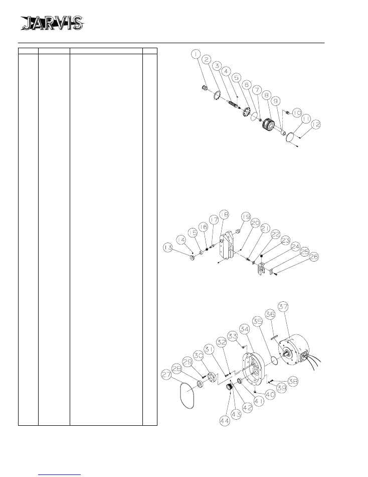
parts diagrams and list
Model Buster V
page 6 of 16
®
JARVIS
6206002;::::
PRODUCTS CORPORATION
33 ANDERSON ROAD, MIDDLETOWN, CONNECTICUT 06457-4926
UNITED STATES OF AMERICA EMAIL.
jarvis.products.corp@snet.net
TEL. 860-347-7271 FAX. 860-347-6978 WWW
.jarvisproducts.com
1
1036103
Thrust Bushing
1
2
1013244
Internal Retaining Ring
1
3
1020144
Torque Knob Shaft
1
4
1030067
Woodruff Key
1
5
1021259
Flanged Bearing Race
1
6
1035163
O-ring
1
7
1007041
Hex Lock Nut
1
8
1006026
Torque Knob
1
9
1021106
Roller Bearing
1
10
1039024
Ball Plunger
8
11
1002239
Torque Knob Cover
1
12
1055482
Pan Head Screw
2
3006005
Torque Knob Assembly
(includes items 1-12)
13
1006022
Lock Pin Knob
2
14
1073037
Socket Set Screw, Cup Pt.
2
15
1036124
Drive End Lock Pin Bushing
1
1036131
Idler End Lock Pin Bushing
1
16
1014059
Compression Spring
2
17
1010213
Drive End Lock Pin
1
1010219
Idler End Lock Pin
1
18
1016246
Drive End Guide Housing
1
1016247
Idler End Guide Housing
1
19
1061202
Guide Plug
2
20
1055494
Socket Set Screw, Special
4
21
1055502
Socket Head Cap Screw
2
22
1058078
Back-up Blade Guide
2
23
1014083
Compression Spring
2
24
1061231
Blade Guide Mounting Plate
2
25
1058061
Blade Guide Insert
4
26
1055490
Pan Head Slotted Screw
12
3058057
Drive End Guide Package
(includes items 13-26)
1
3058056
Idler End Guide Package
(includes items 13-26)
1
27
1035209
O-ring
1
28
1021139
Ball Bearing
1
29
1055948
Socket Head Cap Screw
3
30
1016227
Bearing Retaining Flange
1
31
1055104
Socket Head Cap Screw
4
32
1004069
Split Lock Washer
4
33
1010215
Locator Pin
2
34
1016244
Gear Housing, 60 Hertz
1
1016225
Gear Housing, 50 Hertz
35
1035009
O-ring
1
36
1030096
Square Key
1
37
page 9
Motor (3.3 Hp., 3 Phase):
1
1008077
460/230V, 60 Hz
1008135
380/220V, 50 Hz
38
1055357
Hex Head Screw
8
39
1004032
Flat Washer
8
40
1050771
Hex Socket Pipe Plug
2
41
1035206
Oil Seal
1
42
1055467
Socket Set Screw, Cup Pt.
1
43
1026089
Drive Gear, 60 Hz 28 teeth
1
1026087
Drive Gear, 50 Hz 30 teeth
1
44
1055468
Socket Set Screw, Flat Pt.
1
Motor Accessories, Finned:
1
1035214
Gasket Seal
1021240
Ball Bearing (Front)
1021241
Ball Bearing (Rear)
1063163
Rotor
1035216
Oil Seal
1063176
Electrical Plug
ITEM
PART NO.
PART NAME
QTY
Torque Knob
Assembly
Blade Guide Assembly,
Idler and Drive End
Motor and
Gear Cover Assembly
Torque wrench nut adapter 8030054
Torque wrench 8039138
Set to slip at 60--65 lbf--in
parts diagrams and list
Model Buster V
page 7 of 16
®
JARVIS
6206002;::::
PRODUCTS CORPORATION
33 ANDERSON ROAD, MIDDLETOWN, CONNECTICUT 06457-4926
UNITED STATES OF AMERICA EMAIL.
jarvis.products.corp@snet.net
TEL. 860-347-7271 FAX. 860-347-6978 WWW
.jarvisproducts.com
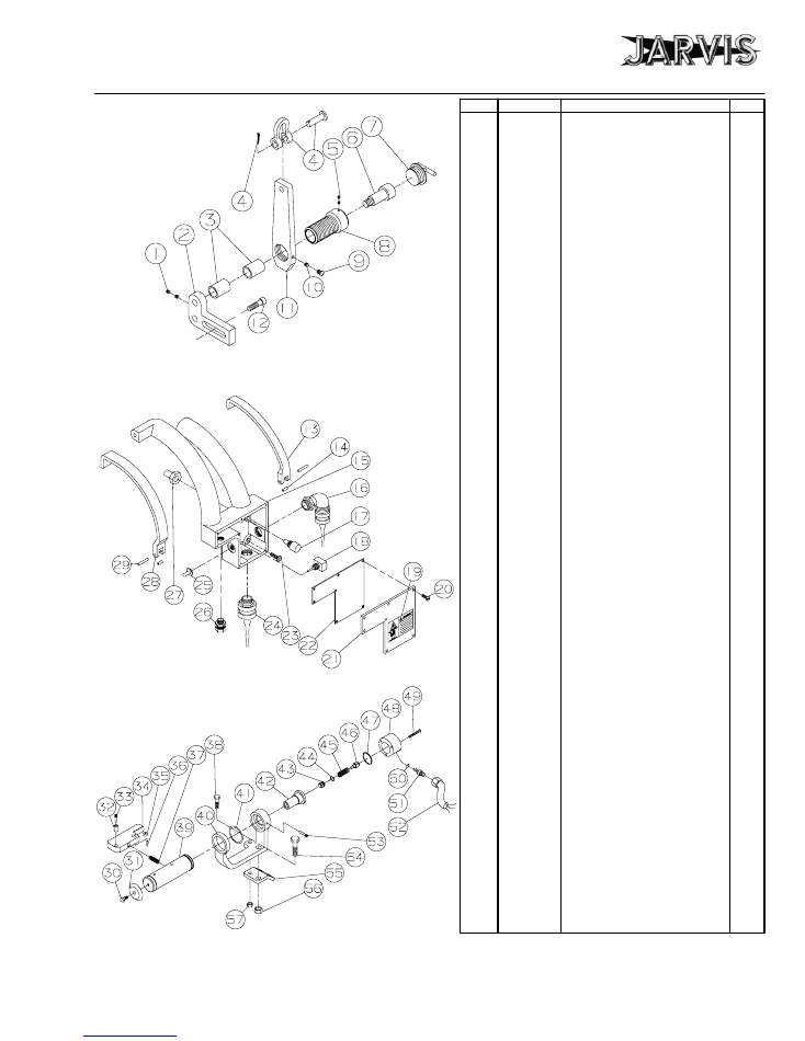
Dual Handle
Control Assembly
Top Handle
Assembly
1
1055721
Socket Set Screw, Cup Pt.
2
2
1042125
Hanger Bracket
1
3
1021493
Cylindrical Bearing
2
4
1028040
Pin and Shackle Link Assy.
1
5
1055469
Socket Set Screw, Cup Pt.
1
6
1055455
Socket Hd Shoulder Screw
1
7
1050243
Handle and Plug
1
8
1016226
Bearing Retaining Housing
1
9
1055471
Thumb Screw
1
10
1061855
Cylindrical Insert
2
11
1028061
Hanger Link
1
12
1055367
Socket Head Cap Screw
2
3061080
Hanger Assembly
(includes items 1-11)
13
1018085
Right Hand Trigger Lever
1
14
1036132
Bushing (incl. with item 15)
2
15
1019086
Switch Housing and Handle
1
16
1011182
Strain Relief Connector
1
17
1005020
Push Button Switch
2
18
1005112
Safety Kill Switch
1
19
1017085
Electric Danger Label
1
20
1055487
Pan Head Screw
7
21
1002223
Switch Hsg Cover w/ item 19
1
22
1061222
Switch Housing Gasket
1
23
1055090
Button Head Screw
4
24
1011223
Strain Relief Connector
1
1011174
Cord Connector, 42V only
25
1063148
Switch Boot
1
26
1011203
Strain Relief Connector
1
27
1035123
Threaded Boot Seal
2
28
1018086
Left Hand Trigger Lever
1
29
1010145
Dowel Pin
2
3019035
Saw Handle Assembly
(includes items 13-23
and 25-29)
30
1055296
Hex Head Screw
1
31
1004182
Washer
1
32
1021314
Bushing
1
33
1010273
Threaded Pin
2
34
1018111
Trigger Lever with items 32,
1
35 and 36
35
1061368
Trigger Roller
1
36
1010275
Dowel Pin
1
37
1014097
Compression Spring
1
38
1055304
Hex Head Screw
1
39
1019118
Handle
1
40
1042164
Handle Bracket
1
41
1013181
External Retaining Ring
1
42
1016316
Switch Housing
1
43
1039044
Plunger with item 44
1
44
1035173
O-ring
1
45
1014098
Compression Spring
1
46
1005059
Push Button Switch
1
47
1035282
O-ring
1
48
1002270
Switch Cover
1
49
1055592
Flat Head Phillips Screw
3
50
1035210
O--ring
1
51
1063220
Electrical Connector w/item 50
1
52
1001049
Wire and Plug
1
53
1010274
Threaded Pin
1
54
1055358
Hex Head Screw
1
55
1042176
Handle Bracket
1
56
1007022
Hex Lock Nut
1
57
1007059
Hex Lock Nut
1
3019073
Top Handle Assembly
(includes items 30-57)
ITEM PART NO.
PART NAME
QTY
Hanger Assembly
*
* tighten to 115 lbf--ft
parts diagram and list
Model Buster V
page 8 of 16
®
JARVIS
6206002;::::
PRODUCTS CORPORATION
33 ANDERSON ROAD, MIDDLETOWN, CONNECTICUT 06457-4926
UNITED STATES OF AMERICA EMAIL.
jarvis.products.corp@snet.net
TEL. 860-347-7271 FAX. 860-347-6978 WWW
.jarvisproducts.com
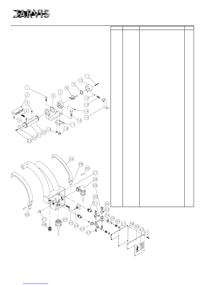
Electric Handles for Export Tools
1
1055304
Hex Head Screw
1
2
1018113
Trigger Lever with item 5
1
3
1010273
Threaded Pin
2
4
1014096
Spring
1
5
1021314
Bushing
1
6
1013181
External Retaining Ring
1
7
1042164
Handle Bracket
1
8
3005017
Switch Assembly
1
9
1035282
O--ring
1
10
1002270
Switch Cover
1
11
1055592
Flat Head Screw
3
12
1035210
O--ring (with item 13)
1
13
1063220
Electrical Connector
1
14
1010274
Threaded Pin
1
15
1001049
Wire with Molded Plug
1
16
1055358
Hex Head Screw
1
17
1042176
Handle Mounting Bracket
1
18
1007022
Hex Lock Nut
1
19
1007059
Hex Lock Nut
1
20
1010297
Roll Pin
1
21
1019128
Switch Handle with item 20
1
22
1004182
Washer
1
23
1055296
Hex Head Screw
1
3019115
Top Handle Assembly
(includes items 1--23)
24
1018085
Right Hand Trigger Lever
1
25
1036132
Bushing (with item 27)
2
26
1010145
Pin
2
27
1019086
Switch Housing and Handle
1
28
1011182
Connector, 90 Degree
1
29
1005114
Switch
2
30
1016354
Switch Housing with item 31
2
31
1035012
O--ring
2
32
1055629
Round Head Screw
4
33
1004423
Washer
8
34
1013198
External Retaining Ring
2
35
1039051
Plunger
2
36
1014119
Spring
2
37
1013197
Internal Retaining Ring
2
38
1061222
Gasket
1
39
1002223
Housing Cover with item 40
1
40
1017085
Danger Label
1
41
1055487
Pan Head Screw
7
42
1007242
Hex Nut
4
43
1042240
Switch Mounting Bracket
1
44
1005112
Toggle Switch
1
45
1055090
Button Head Screw
4
46
1011223
Strain Relief Connector
1
47
1063148
Switch Boot
1
48
1011203
Electrical Connector
1
49
1018086
Left Hand Trigger Lever
1
3019128
Rear Handle Assy (includes
items 24--45 and 47--49)
ITEM PART NO.
PART NAME
QTY
Top Handle
Assembly
Rear Handle
Assembly
parts diagram and list
Model Buster V
page 9 of 16
®
JARVIS
6206002;::::
PRODUCTS CORPORATION
33 ANDERSON ROAD, MIDDLETOWN, CONNECTICUT 06457-4926
UNITED STATES OF AMERICA EMAIL.
jarvis.products.corp@snet.net
TEL. 860-347-7271 FAX. 860-347-6978 WWW
.jarvisproducts.com
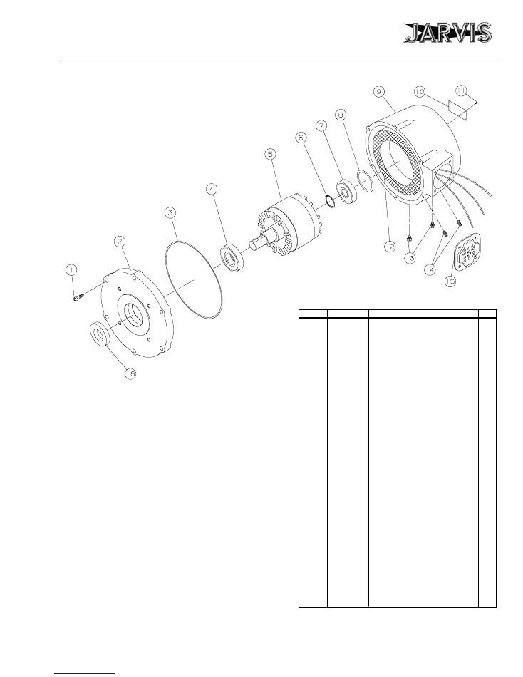
Electric Motor with Smooth Housing
ITEM PART NO.
PART NAME
QTY
1
1055321
Socket Head Cap Screw
6
2
1002342
Motor Cover
1
3
1035456
O--ring
1
4
1021240
Ball Bearing
1
5
3064001
Rotor Assembly
1
6
1013211
Retaining Ring
1
7
1021302
Ball Bearing
1
8
1014141
Wave Spring
1
9
1016406
Motor Housing
1
10
1017158
Information Label
1
11
1055039
Drive Screw
4
12
1063783
Stator, 575V--60Hz
1063576
Stator, 460/230V--60Hz
1063780
Stator, 415V--50Hz
1063778
Stator, 380/220V--60Hz
1063773
Stator, 380/220V--50Hz
1063742
Stator, 115V--50Hz
1063779
Stator, 208V--60Hz
1063712
Stator, 42V--50Hz
13
1051151
Threaded Fitting
2
14
1055849
Socket Set Screw
2
15
1035214
Gasket
1
16
1035216
Seal
1
Stator and Housing Assembly
(includes items 9--14)
3016336
Hsg & Stator 575V--60Hz
3016337
Hsg & Stator 460/230V--60Hz
3016338
Hsg & Stator 415V--50Hz
3016339
Hsg & Stator 380/220V--60Hz
3016340
Hsg & Stator 380/220V--50Hz
3016342
Hsg & Stator 208V--60Hz
3016341
Hsg & Stator 115V--50Hz
3016343
Hsg & Stator 42V--50Hz
For 9 wire and 6 wire motor
hook--ups see page 15
parts diagram and list, specifications
and installation instructions
Model Buster V
page 10 of 16
®
JARVIS
6206002;::::
PRODUCTS CORPORATION
33 ANDERSON ROAD, MIDDLETOWN, CONNECTICUT 06457-4926
UNITED STATES OF AMERICA EMAIL.
jarvis.products.corp@snet.net
TEL. 860-347-7271 FAX. 860-347-6978 WWW
.jarvisproducts.com
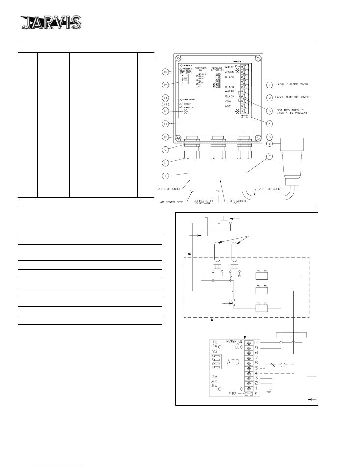
1
1017110
Wiring Diagram, 115V
1
1017111
Wiring Diagram, 220V
1
2
1017085
Electrical Danger Label
1
3
1063311*
Pigtail Fuse, 115V
1
1063312*
Pigtail Fuse, 220V
1
4
1072091
Glass Fuse, 115V
1063862
Glass Fuse, 220V
1
5
1063208
Electrical Outlet
1
6
1063209
Electrical Plug (not shown)
1
7
1001014
Electrical Cord
ft
8
1011240
Strain Relief Connector
3
9
1004211
Sealing Washer
3
10
1007278
Locking Nut
3
11
1032265
Panel
1
12
1073072
Pan Head Slotted Screw
4
13
1029445
Hex Spacer
4
14
1004244
Lock Washer
4
15
1072071
ATD Circuit Board, 115V
1
1072072
ATD Circuit Board, 220V
1
16
1016346
Electrical Box Enclosure
1
3016167
Control Box Assy, 115V
3016190
Control Box Assy, 220V
(items 1, 2, 4, 5 and 7--16)
ITEM
PART NO.
PART NAME
QTY
Electric Control
Box Assembly
* not used in current tools
SPECIFICATIONS
Model Buster V
Motor Power
3.3 hp
2500 W
Operating Voltage
460/230 V, 3 Phase, 60 Hz
all other voltages and 50 Hz available
Capacity
180 head / hour
Control Handles
Electric Dual Anti-tie Down
Distance between guides
19.75 in
502 mm
Blade Length
127 in
3226 mm
Overall Length
57 in
1448 mm
Drive Wheel Speed
530 rpm
Weight
196 lbs
88.9 kg
INSTALLATION INSTRUCTIONS
ALWAYS DISCONNECT THE POWER SUPPLY IN
ACCORDANCE WITH OSHA’S LOCKOUT/TAGOUT
PROCEDURES
(29
CFR
1910.147)
BEFORE
PERFORMING ANY MAINTENANCE OR REPAIRS.
ALL WIRING MUST BE DONE IN ACCORDANCE WITH
NATIONAL, STATE AND LOCAL ELECTRICAL CODES.
White - Neutral
Black - Hot
Green
White
Green
Black
Electric Circuit Board
Safety Kill
Switch
Switches in
Dual Trigger Rear Handle
Switch in
Top Handle
Red/
White
Stripe
Red/
Black
Stripe
Starter Coil
Wire Junction
Box on Saw
AC Power Supply
White
Green
Black
Figure 1
installation instructions
Model Buster V
page 11 of 16
®
JARVIS
6206002;::::
PRODUCTS CORPORATION
33 ANDERSON ROAD, MIDDLETOWN, CONNECTICUT 06457-4926
UNITED STATES OF AMERICA EMAIL.
jarvis.products.corp@snet.net
TEL. 860-347-7271 FAX. 860-347-6978 WWW
.jarvisproducts.com
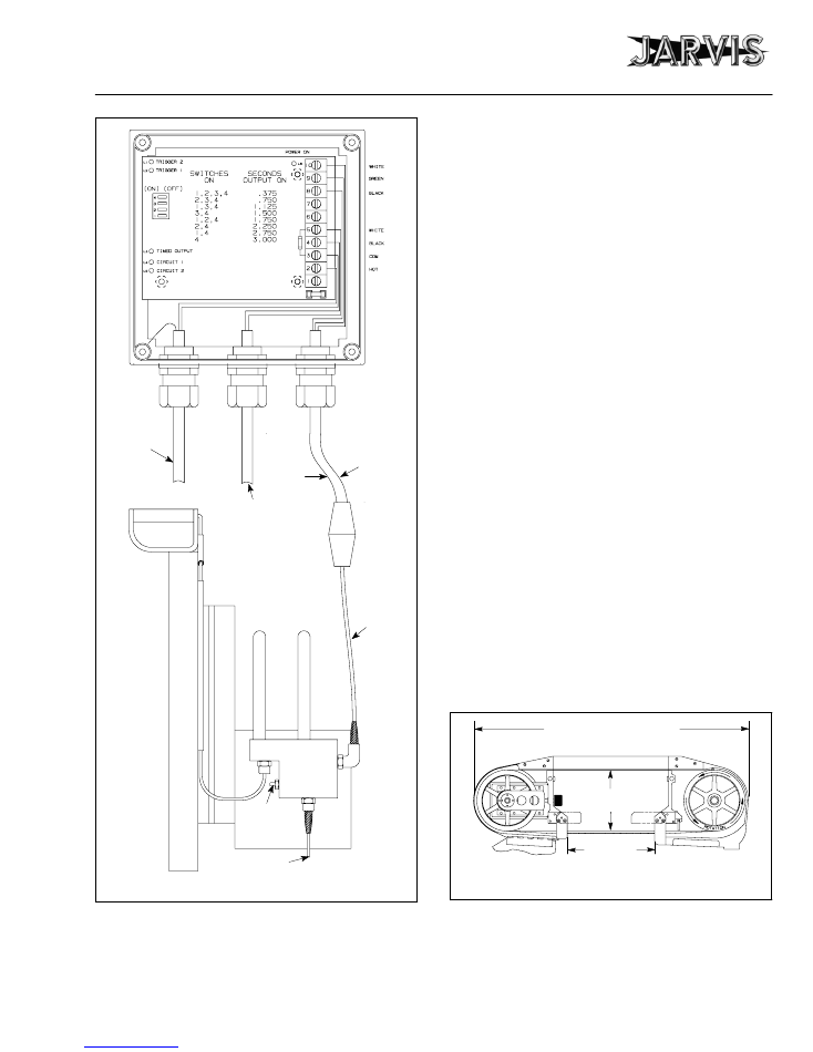
Power from
Starter
Control
Figure 2
To Starter Coil
By Customer
AC Supply
Rear Handles
Top Handle
20 ft.
Safety
Kill
Switch
2 ft.
1 Install the electrical control box in a dry location that
will not be subject to wash downs.
2 Wire the electrical control box.
Refer to figures 1 and 2.
2.1 Attach wires numbered 1, 2 and 3 to the appropri-
ate AC power supply. Check the label (item 1,
page 10) inside the control box cover for the cor-
rect voltage and frequency.
2.2 Attach wires numbered 4 and 5 to a starter coil
(supplied by the customer).
Disconnect any oth-
er source of power to the starter coil. The coil op-
erating voltage is indicated on the label (item 1,
page 10) inside the control box cover.
2.3 The connection between the Buster V and the
control box is pre--wired and is approximately 22
feet long.
3 Wire the motor.
3.1 Follow the wiring diagram shown on page 15 for
all dual voltage (6 or 9 wire) motors. All motors
require a power cord with three leads plus an
earth ground.
3.1.1 Make sure that rear wheel (item 51, Figure
B, page 5) rotates counterclockwise.
Note: the power supply must be con-
nected to perform the above test only.
4 Install the balancer above the work station on a
trolley.
4.1 The trolley should have sufficient travel to allow
the operator to reach the entire work area.
Refer
to figure 3 for dimensions.
12
3
/
4
in.
19
3
/
4
in.
Rail thickness 1 in.
Overall length 57 in.
Figure 3
Frame
Thickness
1
3
/
4
in.
installation instructions
operation instructions
Model Buster V
page 12 of 16
®
JARVIS
6206002;::::
PRODUCTS CORPORATION
33 ANDERSON ROAD, MIDDLETOWN, CONNECTICUT 06457-4926
UNITED STATES OF AMERICA EMAIL.
jarvis.products.corp@snet.net
TEL. 860-347-7271 FAX. 860-347-6978 WWW
.jarvisproducts.com
5 Suspend the Buster V from the balancer.
5.1 Adjust the balancer to the operators’ preference.
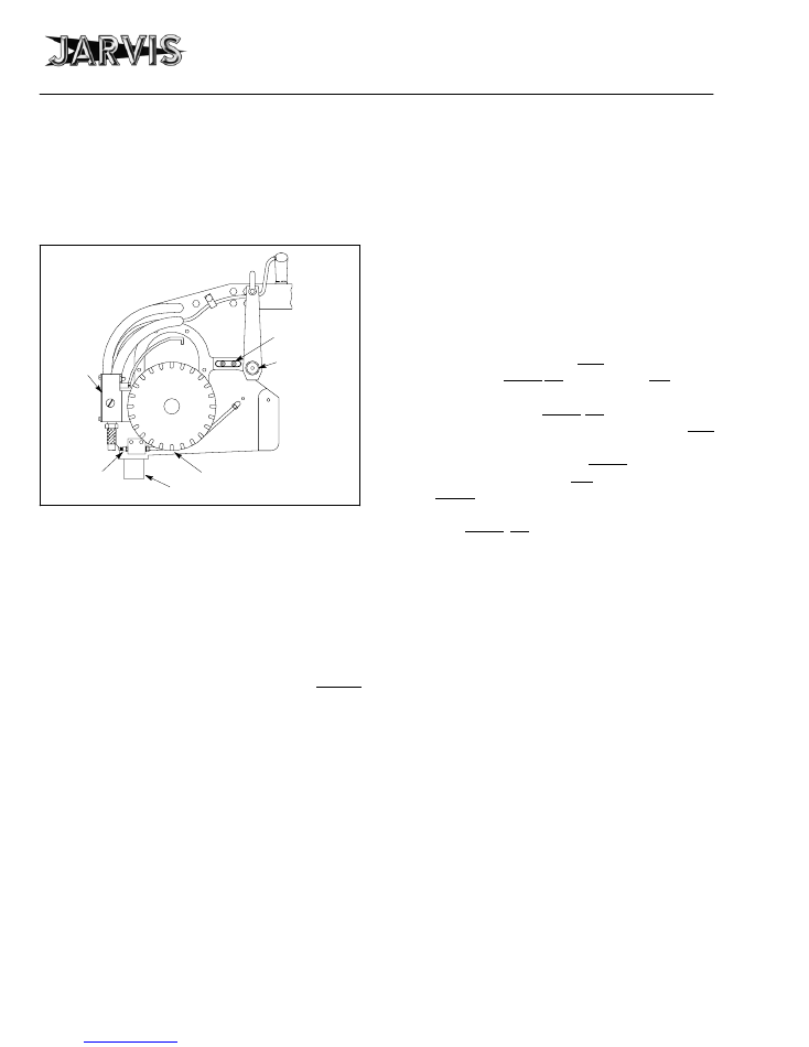
6 Adjust the hanger.
Refer to figure 4 for steps 6.1-6.2.
Safety
Kill
Switch
Water
Hookup
Oil Drain
Adjustment “A”
Figure 4
Adjustment “B”
Water Drain
6.1 Adjustment “A”
to adjust the tilt of the saw
:
S
Move hanger bracket (item 2, page 7) toward
the rear of the Buster V to tip the nose of the
saw down.
S
Move the hanger bracket toward the front of
the Buster V to tip the nose of the saw up.
6.2 Adjustment “B”
to adjust the saw to cut straight
down the backbone
:
S
Turn handle (item 7, page 7) clockwise to cut
more to the right.
S
Turn the handle counter-clockwise to cut
more to the left.
7 Attach a cold or warm water hookup.
Refer to figure 4 for steps 7.1-7.2.
7.1 Attach cold or warm water to quick connect plug
(item 24, Figure B, page 5).
7.2 Attach a drain hose
(supplied by customer)
to the
drain coupling (item 27, Figure B, page 5).
OPERATION INSTRUCTIONS
ALWAYS DISCONNECT THE POWER SUPPLY IN
ACCORDANCE WITH OSHA’S LOCKOUT/TAGOUT
PROCEDURES
(29
CFR
1910.147)
BEFORE
PERFORMING ANY MAINTENANCE OR REPAIRS.
1 Turn on the power.
2
Prior to use or daily,
perform the following tests.
2.1 Make sure that the dual anti-tie down control
handles (the top and the rear handles) are work-
ing correctly.
Depress
each trigger separately
and the tool should not start.
Depress
one trigger,
then pause one second and depress the other trig-
ger and the tool should not start.
Repeat
this
procedure reversing the triggers.
Depress
both
triggers simultaneously (within one half second
of each other) and the tool should start. With the
tool running,
release
one trigger and the tool
should stop.
Continue
holding the depressed
trigger and then depress the other trigger. The
tool should not start.
Repeat
this procedure
holding the other trigger.
If the tool malfunc-
tions, remove it from service and report the prob-
lem to your supervisor immediately
.
2.2 Make sure that the Buster V moves freely on its
balancer.
3 Making the cut.
If an elevating platform is used, the operator can keep
the Buster V in a horizontal position during most of
the split.
Always avoid using pressure; instead, guide the Bust-
er V.
Step 3.1 is necessary only during the operators’
learning period.
3.1 Mark the center of the backbone of the beef with
a knife.
3.2 Start the Buster V.
3.3 Saw through the tail bone using the knife mark as
a guide.
operation instructions
maintenance instructions
Model Buster V
page 13 of 16
®
JARVIS
6206002;::::
PRODUCTS CORPORATION
33 ANDERSON ROAD, MIDDLETOWN, CONNECTICUT 06457-4926
UNITED STATES OF AMERICA EMAIL.
jarvis.products.corp@snet.net
TEL. 860-347-7271 FAX. 860-347-6978 WWW
.jarvisproducts.com
3.3.1 The idler end of the Buster V should be
pointing upward while sawing through the
tail bone.
3.3.2 Do not pressure the Buster V; guide the
Buster V.
3.4 When the tail bone hits the crossbeam of the
Buster V, saw until the tail bone breaks apart and
the Buster V is allowed to continue its path down
the backbone of the beef.
3.4.1 The drive end of the Buster V should be low-
er than the idler end while sawing through
the tail bone.
3.5 After the tail and aitch bones have been split, saw
through the loin area.
3.5.1 The Buster V should be in a horizontal posi-
tion during this cut.
3.5.2 Do not pressure the Buster V; guide the
Buster V to ensure a straight cut.
3.6 Saw through the shoulder and neck of the beef.
3.6.1 The idler end of the Buster V should be
pointing downward while sawing through
the shoulder and neck.
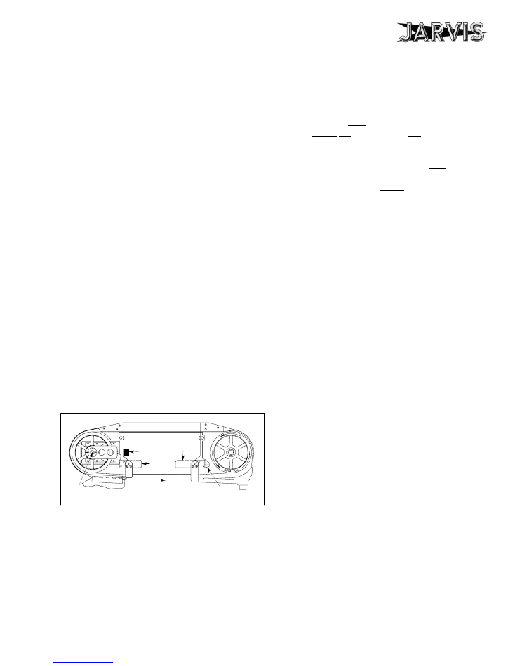
MAINTENANCE INSTRUCTIONS
water
manifold
torque
knob
grease
fitting
blade
guide
blade
guide
tooth direction
ALWAYS DISCONNECT THE POWER SUPPLY IN
ACCORDANCE WITH OSHA’S LOCKOUT/TAGOUT
PROCEDURES
(29
CFR
1910.147)
BEFORE
PERFORMING ANY REPAIRS OR MAINTENANCE.
1 DAILY:
1.1 The Buster V is equipped with dual anti-tie down
control handles (the top and the rear handles).
Check for the correct operation of the dual anti-
tie down control handles
prior to use or daily.
Depress
each trigger separately and the tool
should not start.
Depress
one trigger, then pause
one second and depress the other trigger and the
tool should not start.
Repeat
this procedure re-
versing the triggers.
Depress
both triggers si-
multaneously (within one half second of each
other) and the tool should start. With the tool run-
ning,
release
one trigger and the tool should
stop.
Continue
holding the depressed trigger
and then depress the other trigger. The tool
should not start.
Repeat
this procedure holding
the other trigger.
If the tool malfunctions, repair
or remove it from service immediately
.
Note: the power supply must be connected to
perform the above operation only.
1.2 Clean and check the blade guide assemblies:
Re-
fer to the parts diagram on page 6 for referenced
items.
Note: the backup blade guides can be replaced or
rotated without removing the blade guide mount-
ing plate from the saw.
1.2.1 Remove two (2) set screws (item 20).
1.2.2 Slide the blade guide mounting plate (item
24) out of the guide housing (item 18).
1.2.3 Remove six (6) screws (items 26).
1.2.4 Rotate or replace the blade guide inserts
(item 25) as required.
1.2.5 Insert a 0.022 feeler gage between the blade
guide inserts.
1.2.6 Apply a light pressure to the outside of the
blade guides.
1.2.7 Tighten the six (6) screws (item 26).
1.2.8 Remove screw (item 21).
1.2.9 Rotate or replace the back--up blade guide
(item 22) as required.
1.2.10 Tighten the screw (item 21).
maintenance instructions
Model Buster V
page 14 of 16
®
JARVIS
6206002;::::
PRODUCTS CORPORATION
33 ANDERSON ROAD, MIDDLETOWN, CONNECTICUT 06457-4926
UNITED STATES OF AMERICA EMAIL.
jarvis.products.corp@snet.net
TEL. 860-347-7271 FAX. 860-347-6978 WWW
.jarvisproducts.com
1.2.11 Tighten locknut (item 50, Figure B, page 5)
to 80 lbf--ft.
Jarvis
wrench 8039120 is
available.
1.3 Check the front bearings:
1.3.1 Grease the front wheel bearings through
grease fitting (item 5, Figure A, page 4) with
USDA approved wheel bearing grease.
1.4 Check the oil in the gear housing:
1.4.1 Check the level of oil in the gear housing
(item 34, page 6).
1.4.2 Change the oil if these conditions exist:
•
The oil contains water.
•
The oil is dark or gritty.
•
Any bearing is being replaced.
1.4.2.1 The saw should be tilted rearward and
filled with approximately 1
1
/
2
quarts of
SAE 80W - 90 EP hypoid gear lube.
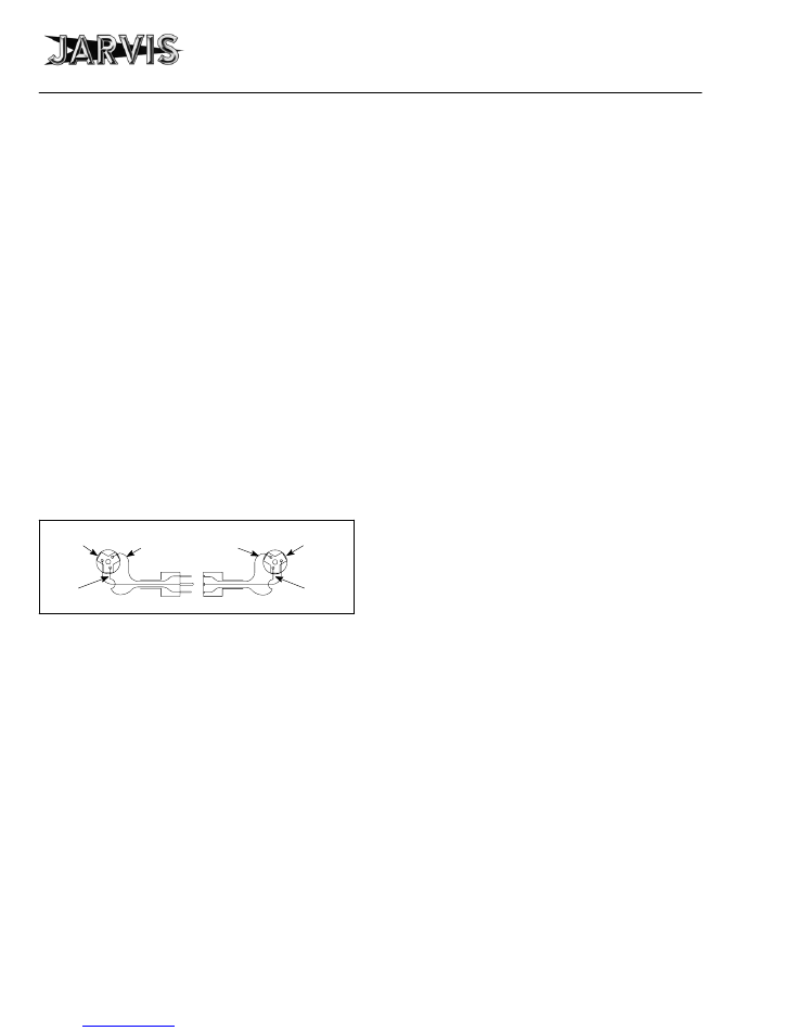
1.5 Check the cord and plug assembly:
1.5.1 Check the cord and plug assembly (items
5-7, page 10) for wear and replace if neces-
sary.
Green Screw
Green Wire
Bronze Screw
Black Wire
Silver Screw
White Wire
Green Screw
Green Wire
Black Screw
Black Wire
Silver Screw
White Wire
2 WEEKLY:
Refer to page 6 for referenced items unless otherwise noted.
2.1 Clean the torque knob:
2.1.1 Remove the torque knob (item 27, Figure A,
page 4) from the Buster V.
2.1.2 Remove screws (item 12, page 6).
2.1.3 Remove cover (item 11, page 6).
2.1.4 Turn the torque knob over.
2.1.5 Remove retaining ring (item 2, page 6).
2.1.6 Remove shaft (item 3, page 6) assembly.
2.1.7 Clean all grease out of the torque knob.
2.1.8 Turn the torque knob so that ball plungers
(item 10, page 6) are visible.
2.1.9 Pour oil onto the ball plungers.
2.1.10 Work each ball plunger up and down with a
wooden dowel to lubricate the springs.
2.1.11 Apply
Jarvis
1315 White Grease
to the ball
plunger surface and to the bearing (item 9,
page 6).
2.1.12 Install the shaft (item 3).
2.1.13 Rotate the shaft slightly until you can feel
the balls fall into their holes.
2.1.14 Install the retaining ring (item 2).
2.1.15 Tighten the torque knob to 60--65 lbf--in.
Torque wrench nut adapter 8030054 and
torque wrench 8039138 are available.
2.1.16 Install the torque knob cover (item 11).
2.1.17 Install the screws (item 12).
2.1.18 Install the torque knob assembly on the
Buster V.
3 WHEN NECESSARY:
3.1 Replace the blade:
3.1.1 Open doors (item 3, Figure A, page 4 and
item 41, Figure B, page 5).
3.1.2 Loosen the torque knob (item 27, Figure A,
page 4) by turning it fully counter-clock-
wise.
3.1.3 Raise the blade guide assemblies (item 29,
Figure A, page 4 and item 63, Figure B, page
5) so that both guide assemblies are parallel
to the floor.
3.1.4 Install the blade with teeth pointing inward,
toward the frame.
3.1.5 Tighten the torque knob until it “clicks.”
3.1.6 Twist the blade so that the teeth point down-
ward; set the blade guide assemblies down
over the blade.
3.1.7 Close the doors.
3.1.8 Tighten the torque knob after saw has run a
few minutes.
3.2 Tighten the front wheel:
3.2.1 Turn the front bearing locknut (item 6, Fig-
ure A, page 4) clockwise until hand tight.
wiring diagrams
Model Buster V
page 15 of 16
®
JARVIS
6206002;::::
PRODUCTS CORPORATION
33 ANDERSON ROAD, MIDDLETOWN, CONNECTICUT 06457-4926
UNITED STATES OF AMERICA EMAIL.
jarvis.products.corp@snet.net
TEL. 860-347-7271 FAX. 860-347-6978 WWW
.jarvisproducts.com
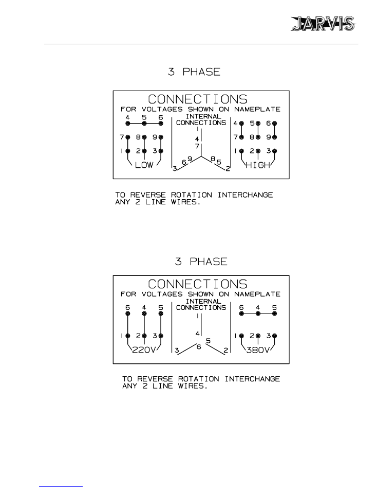
Nine Wire Motor Hook--up
Six Wire Motor Hook--up
1017296
1017301

Model Buster V
page 16 of 16
®
JARVIS
6206002;::::
PRODUCTS CORPORATION
33 ANDERSON ROAD, MIDDLETOWN, CONNECTICUT 06457-4926
UNITED STATES OF AMERICA EMAIL.
jarvis.products.corp@snet.net
TEL. 860-347-7271 FAX. 860-347-6978 WWW
.jarvisproducts.com
PRODUCTS CORPORATION
PRODUCTS CORPORATION
33 ANDERSON ROAD, MIDDLETOWN, CONNECTICUT 06457--4926
UNITED STATES OF AMERICA EMAIL.
jarvis.products.corp@snet.net
TEL. 860--347--7271
•
FAX. 860--347--6978
•
WWW.jarvisproducts.com
®
JARVIS
6206002;::::