Full Text Searchable PDF User Manual
Change for life
GREE ELECTRIC APPLIANCES, INC.OF ZHUHAI
Air-to-water Heat Pump Monobloc Versati
Design and Selection

CONTENTS
1 Installation Example ������������������������������������������������������������������������������� 1
2 Model Selection �������������������������������������������������������������������������������������� 3
2.1 Speculations of Power Supply ................................................................................... 3
2.2 Operation Conditions ................................................................................................. 3
2.3 Flowchart of Model Selection ..................................................................................... 3
2.4 Design Principle ......................................................................................................... 3
3 Selection of the Underfloor Coils ���������������������������������������������������������� 4
3.1 Calculation of Unit Load for Floor Heating ................................................................. 4
3.2 Selection of Tube Spacing of the Underfloor Coils ..................................................... 4
4 Quantity and Location of the Water Traps and Collectors ������������������ 5
4.1 Design Requirements on Loop Quantity for Circulation Water ................................... 5
4.2 Requirements on Installation of the Water Trap (Collector) ....................................... 6
5 Section of FCU ���������������������������������������������������������������������������������������� 7
5.1 FCU Type Selection ................................................................................................... 7
5.2 Matching of Capacity .................................................................................................. 7
6 Selection of the Water Tank ������������������������������������������������������������������� 8
6.1 Specifications of the Water Tank ................................................................................ 8
6.2 Volume Selection of the Water Tank .......................................................................... 8
7 Examples for Model Selection ��������������������������������������������������������������� 8
7.1 General Introduction to the Example Project ............................................................ 8
7.2 Heat Load Calculation ................................................................................................ 9
7.3 Model Selection ........................................................................................................ 10
1
Design & Selection
1 Installation Example
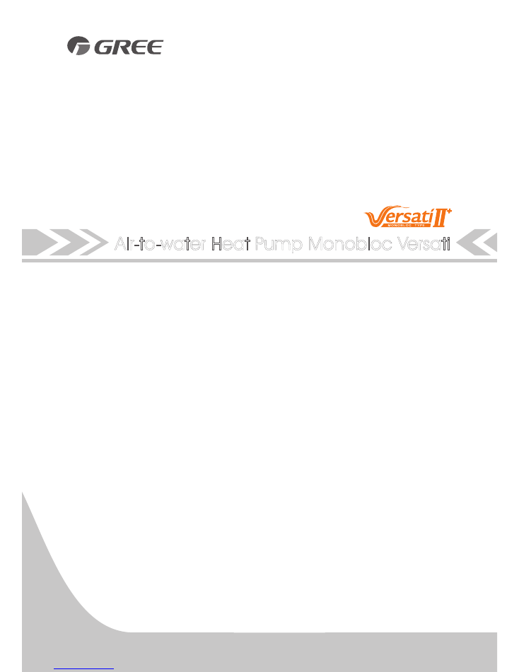
CASE 1: Connecting Heat Emitters for Heating and Cooling(Under floor loop,Fan Coil Unit,and
Radiator)
Notes
①
The two-way valve is very important to prevent dew condensation on the floor and Radiator while cooling
mode;
②
Type of thermostat and specification should be complied with installation of this manual;
③
The Bypass valve must be installed to secure enough water flow rate, and should be installed at the
collector.
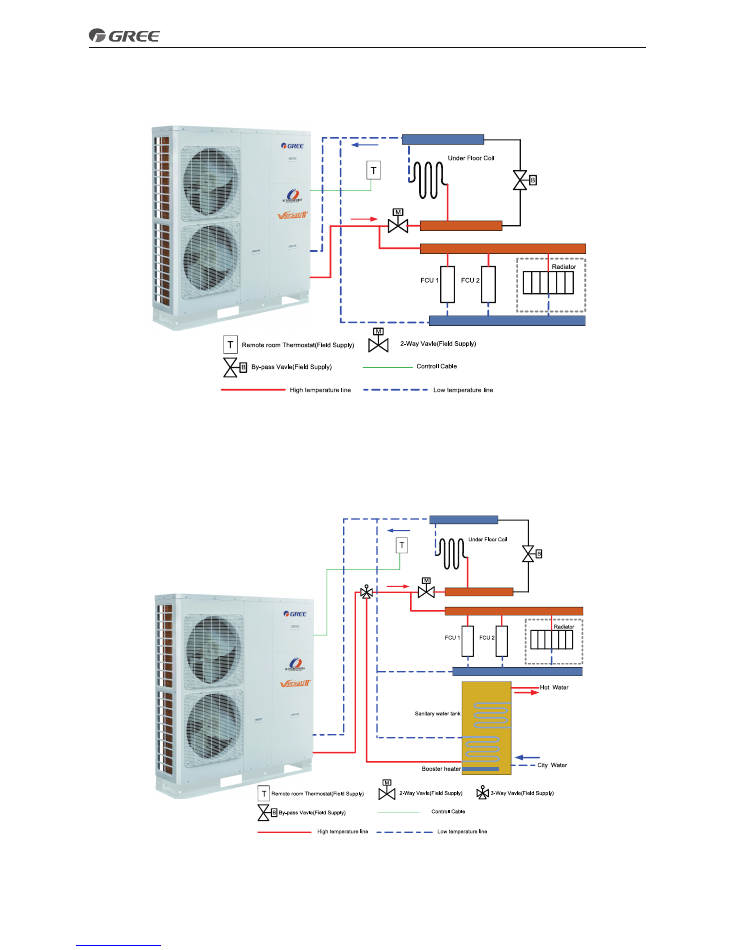
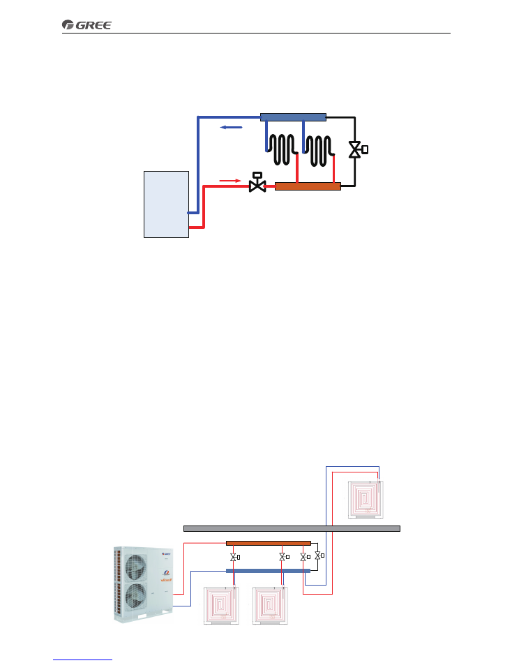
CASE 2: Connecting Sanitary Water Tank
Notes
①
In this case, three-way valve should be installed and should be complied with installation of this manual;
②
Sanitary water tank should be equipped with internal electric heater to secure enough heat energy in the
very cold days;
2
Design & Selection
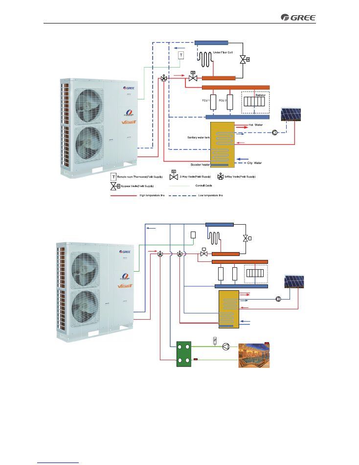
CASE 3 : Connecting Solar thermal system
Two-way valve is very important to prevent dew condensation on the floor and Radiator while cooling mode.
CASE 4 : Connecting Swimming pool system
B
M
T
3-way valve 1
3-way valve 2
City water
Radiator
FCU 1F
CU 2
Under Floor Coil
Booster heater
Sanitary water tank
Hot water
Notes:
①
Two-way valve is very important to prevent dew condensation on the floor and Radiator while cooling
mode.
②
3-Way valve 1 is controlled by user,while the pool pump is actived, 3-Way valve 1 switches to
③
pool loop;while the pool pump is shuted down,3-Way valve 1 switches to under floor/FCU loop.
④
3-Way valve 2 is automatic controlled by monobloc unit,while running water heating mode,3-Way valve
2 switches to water tank loop;while running cooling/heating mode,3-Way valve 2 switches to under floor/FCU
loop.
3
Design & Selection
2 Model Selection
2.1 Speculations of Power Supply
Two choices of Power Supply
380~415V-3PH-50Hz
220~240V-1PH-50Hz
GRS-CQ10Pd/NaC-K
GRS-CQ8.0Pd/NaC-K
GRS-CQ12Pd/NaC-M
GRS-CQ14Pd/NaC-M
2.2 Operation Conditions
Capacities and power inputs are based on the following conditions (floor heating /cooling )
a. Cooling conditions
b. Heating conditions
Indoor Water Temp 23°C/18°C;
Indoor Water Temp 30°C/35°C;
Outdoor Air Temp 35°C DB/24°C WB
Outdoor Air Temp 7°C DB/6°C WB
Capacities and power inputs are based on the following conditions (FCU or radiator)
a. Cooling conditions
b. Heating conditions
Indoor Water Temp 12°C/7°C;
Indoor Water Temp 40°C/45°C;
Outdoor Air Temp 35°C DB/24°C WB
Outdoor Air Temp 7°C DB/6°C WB
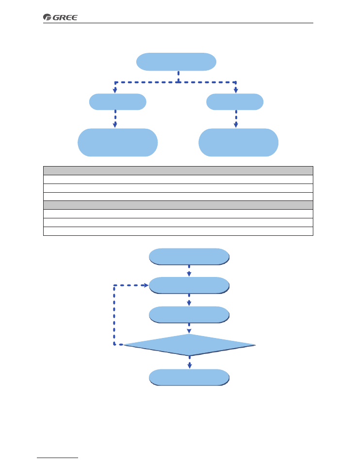
2.3 Flowchart of Model Selection
Calculate the load
Preliminary selection
of unit
Finish unit selection
Actual capacity
>
Load
Calculate the load
YES
NO
2.4 Design Principle
◆
Cooling: capacity of the unit ≥ cooling load of the air conditioning
◆
Heating: capacity of the unit ≥ max{ heating load, floor heating load, water heating load}
◆
Water Tank: it should be selected based on the sanitary outfit or quantity of users. Each unit can
accommodate only one water tank.
4
Design & Selection
3 Selection of the Underfloor Coils
3.1 Calculation of Unit Load for Floor Heating
Empirical Values of Floor Heating Load Per Square Meter
House W/m
2
Dining Room
100~120
Mater Room
100~110
Guest Room
110~130
Study Room
90~110
Villa W/m
2
Dining Room
110~140
Mater Room
100~120
Guest Room
100~130
Study Room
100~120
Notes
①
Villas whose load is generally larger than the houses should take the value between the middle and the
maximum empirical values listed above.
②
The top lever whose load is generally larger than the middle or bottom layer should take the maximum
empirical value.
③
The guest room whose load is generally much large should take the value between the intermediate and
the maximum empirical values listed above.
④
For those whose external walls or glass areas are large, it is recommended to take the load calculation.
⑤
The heating load for the bathroom is generally 500W/room.
3.2 Selection of Tube Spacing of the Underfloor Coils
Tube spacing of the underfloor coils which will directly affect heat dissipation of the floor depends on the
tube material, indoor design temperature, supply water temperature and floor material.
Heat Dissipation of Commonly Used Coils
(Tube material: PE-X, Indoor temperature:18°C, Average water temperature:45°C)
Floor Material
Thermal Resistance
m
2
·K/W
Tube Spacing
mm
Heat Dissipation
W/m
2
Tube Spacing
mm
Heat Dissipation
W/m
2
Stone
0.02
200
147.0
150
159.8
Wood
0.075
200
111.2
150
117.8
The dissipated heat of the floor coil is larger than the load for the floor heating system; however the
deviation cannot be larger than 10%.
3.3 Selection of Loop Quantity of Coils for Each Room
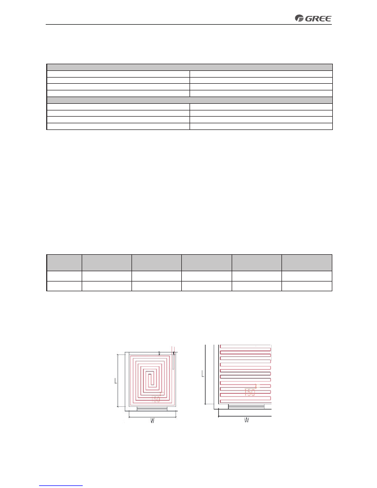
3.3.1Type of Underfloor Coils
When selecting underfloor coils, we should consider both their comfortability and heating capacity. The most
commonly used coils are as shown below.
Square-shaped Coil (Recommended)
U-shaped Coil
Length of coils are calculated as below:
Square-shaped coil: =L*W/tube spacing=area/tube spacing
U-shaped coil: =L-1+L*W/tube spacing=L-1+area/tube spacing
The reason why the square-shaped coils are recommended is because they can keep even temperature
5
Design & Selection
distribution. Special demand can be met by adjusting the tube spacing.
Distance from the room to the water trap/collector should be estimated according to the actual conditions of
the project and generally should not exceed 30m.
3�3�2 Selection of Loop Quantity for Each Room
◆
Length of a single loop should not exceed 100m. If so, it should be divided into multiple loops.
◆
Area of a single loop=tube length×tube spacing=100m×150mm=15m
2
B
M
Underfloor Coil
Selected
Unit
Length of underfloor coils is recommended to be within 100m and length of each branch should be kept the
same to the most extent.
4 Quantity and Location of the Water Traps and Collectors
The water trap (collector) is a kind of device for distributing water for the water supply and return tubes.
4.1 Design Requirements on Loop Quantity for Circulation Water
1) One water trap (collector) is allowed for at most eight loops. When quantity of loops exceeds 12, then two
traps (collectors) should be used, or it will cause uneven water distribution.
2) The maximum flow rate of the water trap (collector) should be less than 0.8m/s.
3) The inlet and outlet of each loop should be connected to the water trap (collector) and the inner diameter
of the water trap (collector) should be or larger than that of the main water supply/return tube.
Calculation of loop quantity for circulation water can be done as per the forma below
N=A/A1
N——loop quantity
A—— total floor heating area (unit: m
2
)
A1—— floor heating area per single loop (unit: m
2
)
Example for how to calculating the floor heating area per single loop: when the tube length is 120m, and
tube spacing is 200mm, then the floor heating area per single loop is 120×0.2=24m2.
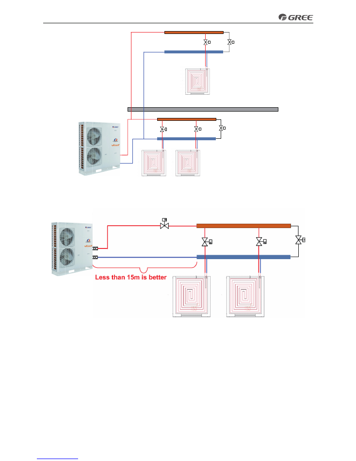
4) One trap (collector) cannot be used for different floors, or it would cause uneven water distribution.
B
1F
2F
M
M
M
Wrong Design
6
Design & Selection
B
1F
2F
M
M
Correct Design
B
M
5) Distance between the unit and the water trap (collector) should be within 15m. If the distance exceeds
20m, then it is required to calculate the hydraulic power.
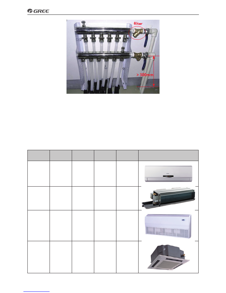
4.2 Requirements on Installation of the Water Trap (Collector)
1) The water trap (collector) should be installed on the wall or inside the special box. For housing
constructions, it is generally installed in the kitchen.
2) The valve for the water trap (collector) should be installed horizontally and keep a distance of at least
300mm to the ground.
3) The water supply valve should be installed upstream of the water trap (collector) and the return valve
should be installed downstream of the water trap (collector)
4) A filter is required upstream of the water trap (collector).
7
Design & Selection
5 Section of FCU
5.1 FCU Type Selection
The air-water fan coil unit is optional for Versati units
5.2 Matching of Capacity
Load of the FCU is better to be between 70%~120% of the Versati unit.
Notes:
①
When load of the FCU is too small, the unit would start/stop frequently, which is adverse for oil return.
②
When load of the FCU is too large, the unit would always run under high frequency, which is unhelpful for
energy conservation.
Type
Air Volume
(m
3
/h)
Cooling
Capacity
(kW)
Heating
Capacity
(kW)
Static
Pressure
(Pa)
Appearance
Wall mounted
type
166~1020
2.1~5.4
3.15~8.5
——
Concealed
ceiling type
213~2380
1.85~12.8
3.1~21
12, 30
Floor ceiling
type
213~2040
1.9~10.8
2.8~16.2
——
Cassette type
480~1700
4.5~9
6.8~13.7
——
8
Design & Selection
6 Selection of the Water Tank
6.1 Specifications of the Water Tank
SXVD200LCJ/A-K
220~240V-1Ph-50Hz
A single coil with the electric heater is integrated, used for floor heating system
SXVD300LCJ/A-K
SXVD200LCJ2/A-K
220~240V-1Ph-50Hz
Dual coils with the electric heater are integrated, used for floor heating system and the solar system
SXVD300LCJ2/A-K
SXVD200LCJ/A-M
380~415V-3Ph-50Hz
A single coil with the electric heater is integrated, used for floor heating system
SXVD300LCJ/A-M
SXVD200LCJ2/A-M
380~415V-3Ph-50Hz
Dual coils with the electric heater are integrated, used for floor heating system and the solar system
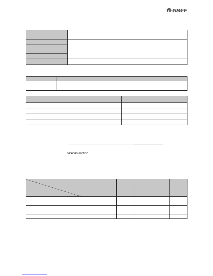
6�2 Volume Selection of the Water Tank
6.2.1 Selection Based on Water Consumption Per Capita
Building Type
Unit
Daily Water Consumption (L)
Water Temperature (°C)
House
Per person, Per day
40~80
60
Villa
Per person, Per day
70~110
60
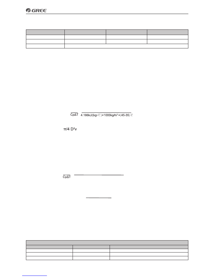
6�2�2 Selection Based on Sanitary Utensils
Utensil Type
Daily Water
Consumption (L)
Water Temperature (°C)
Bathtub, Sprinkler system (with shower)
150
40
Bathtub, Sprinkler system (without shower)
125
40
Shower
70~100
37~40
Wash Basin
3
30
6� 2�3 Selection of the Water Tank
Selection of the water tank should consider the flow rate of the shower head, duration of use per person
and daily water consumption.
Volume of the Water Tank=
t(design temperatuere)-t(entering cold water temperatuere)
t(water tank temperatuere set point)-t(entering cold wa ter temperature)
•consumptio
n
t (design temperature): generally it is 60°C ;
t (entering cold water temperature): it differs for different regions.
t ( water tank temperature set point): it is the target heating temperature of the water tank
α: correction factor
Empirical Values for Volume Correction of the Water Tank
Duration of Use
(min/Person)
Flow Rate of the Shower Head
(L/min)
10
15
20
25
30
40
4
0.48
0.71
0.94
1.18
1.42
1.89
6
0.71
1.06
1.42
1.77
2.12
2.83
8
0.95
1.42
1.89
2.36
2.83
3.77
10
1.18
1.77
2.36
2.95
3.54
4.72
15
1.76
2.65
3.54
4.42
5.31
7.08
Empirical values are worked out under conditions of 80L consumption (per day per person), 8L/min flow rate
of the shower head, and 10 minutes use duration per person.
7 Examples for Model Selection
7�1 General Introduction to the Example Project
For a two-floor house, there is a master room and a both room for each floor and both of
them require floor heating. Other rooms use the heat pump for heating in winter. The master
room covers 28m
2
and the both room covers 12m
2
.
9
Design & Selection
7.2 Heat Load Calculation
7.2.1 Load Calculation of a Single Floor
Room
Area
Heat Index (W/m
2
)
Heat Load (W)
Master Room
28
82
2296
Bathroom
12
72
900
Total Load
2296+900=3196w
7.2.2 Arrangement Design of the Underfloor System for A Single Floor
Assumed conditions: the floor is cement or ceramics, the normal external diameter of the heating pipe is
20mm, thickness of the stuffer is 50mm, thickness of PS foam insulation is 20mm, supply water temperature is
45°C , return water temperature is 35°C , indoor design temperature is 20°C .
Average Temperature of the Heating Pipe=(45+35)/2=40°C
7.2.3 Arrangement Design of the Underfloor System for the Bath Room
Heat load of the bath room is 900W, heat dissipation per unit area is 75W/m2, tube spacing of the heat pipe
is 30mm, and heat loss is 25.4 W/m2, then the total heat loss is:
25.4×12=304.8W
Based on the heat load listed in the table above, the heating load for the bathroom is:
900+304.8=1204.8W
According to the formula Q=CρGΔT, the flow rate of the heating pipe for the bathroom is:
G=
1.2048kJ/1/3600 h
Q
=0.104m
3
/h
=
If the outer diameter of the heating pipe is 20mm and thickness is 2mm, then the minimum flow for the
heating pipe is:
G=
=3.14/4*
(
20-2*2
)
2
*10
-6
*0.25*3600 =(0.18m
3
)/h
It can be see that the arranged piping system for the bathroom does not meet the technical requirement and
must be used in common for the master room.
7.2.4 Arrangement Design of the Underfloor System for the Master and Both Rooms
According to the calculation results, the total heat load for the master and bath rooms is 3196W, heat
dissipation per unit area is 82W/m2, tube spacing of the heating pipe is 300mm, and heat loss 25.4 W/m
2
is,
then the total heat loss is:
3196+1016=4212W
According to the formula Q= CρGΔT, the flow rate is
G=
4.212kJ/(1/3600h)
Q
=0.3622m
3
/
>
0.18m
3
/h
=
4.186kJ/(kg·
℃
)*1000kg/m
3
*(45-35)
℃
Loop quantity is 0.3622/0.18=2.012 and the round-off number is 2.
7.2.5 Check
◆
A. Check for the flow rate
0.3622/2
=0.2503m/s
3.14*0.008
2
*3600
Floor rate of each loop is within 0.25~0.5m/s and the system can run stably.
◆
B. Check for the tube length
When the average tube spacing is 30mm, the required length of the heating pipe per square meter is 3.5m,
length of total coils is 3.5×40=140 and length for each loop is 140/2=70.
It can be seen that the length for each loop is less than 120m and there it meets the design requirement.
◆
C. Check for the ground average temperature
tp=tn+9.82×(qx/100) 0.969=20+9.82×(82/100) 0.969=28°C
Upper Limits and Average Floor Temperature
Average Floor Temperature
Area
Average Temperature
Maximum Temperature
Long-term Dwelling Area
24~26
28
Short-term Dwelling Area
28~30
32
Nobody Area
35~40
42

10
Design & Selection
7�3 Model Selection
Heat demand for a single layer: 3196W
Heat loss for a single layer: 1016W
Total heat load for a single layer: 4212W
Total heat load of the building: 8424W
Capacity of the main unit should be larger than 8424W, so we can select:
GRS-CQ10Pd/NaC-K