Full Text Searchable PDF User Manual
M2000001 v1.4
2RCI User Manual

2
GKD Technik Ltd
M2000001
Issue
Date
Changes
Job
V1.0
01/09/2014
Document created. Update from the NPN V5 version
V1.1
26/11/2014
Add Slew and I/O module options
V1.2
04/07/2016
General update and reformat of entire document
V1.3
16/08/2017
Added new Virtual wall functionality
V1.4
20/11/2017
Update to new branding and part numbers
Change History

3
GKD Technik Ltd
M2000001
Contents
Change History
2
Page no
Introduction
Lifting Operation
Lifting Mode
Operation
4
4
4
5
5
5
5
6
6
6
6
7
7
8
8
9
12
13
14
15
15
16
Front Screen
Lifting Duties
Selection of Lift Attachment
-
Options
Manual Lifting Duty Selection (Jib and Forks Versions)
Hook/Bucket Duty
Forks Duty
Jib Duty
Mode Menu
Setting a Height Limit
Cancelling a Height Limit
Setting a Slew Limit
Dig Mode
16
Automatic Slew Based Lifting Duties
Depth Setting
Full Motion Cut on Overload
System Layout
Test Function
Component Location
Virtual Walls
4
GKD Technik Ltd
M2000001
Introduction
This is the operation manual for the 2RCI range of rated capacity indicators.
This product is a safety product.
WARNING
-
DURING NORMAL OPERATION THE RATED CAPACITY OF A CRANE SHOULD NOT BE
EXCEEDED. THEREFORE THE OVERLOAD WARNING SHOULD NOT BE USED AS A NORMAL MODE
OF OPERATION. STATUTORY REQUIREMENTS DO NOT PERMIT THE RATED CAPACITY TO BE
EXCEEDED EXCEPT FOR THE PURPOSE OF TESTING.
THIS RCI IS NOT FOR USE IN EXPLOSIVE ATMOSPHERES.
ADJUSTMENT BY NON AUTHORIZED PERSONNEL WILL INVALIDATE THE WARRANTY.
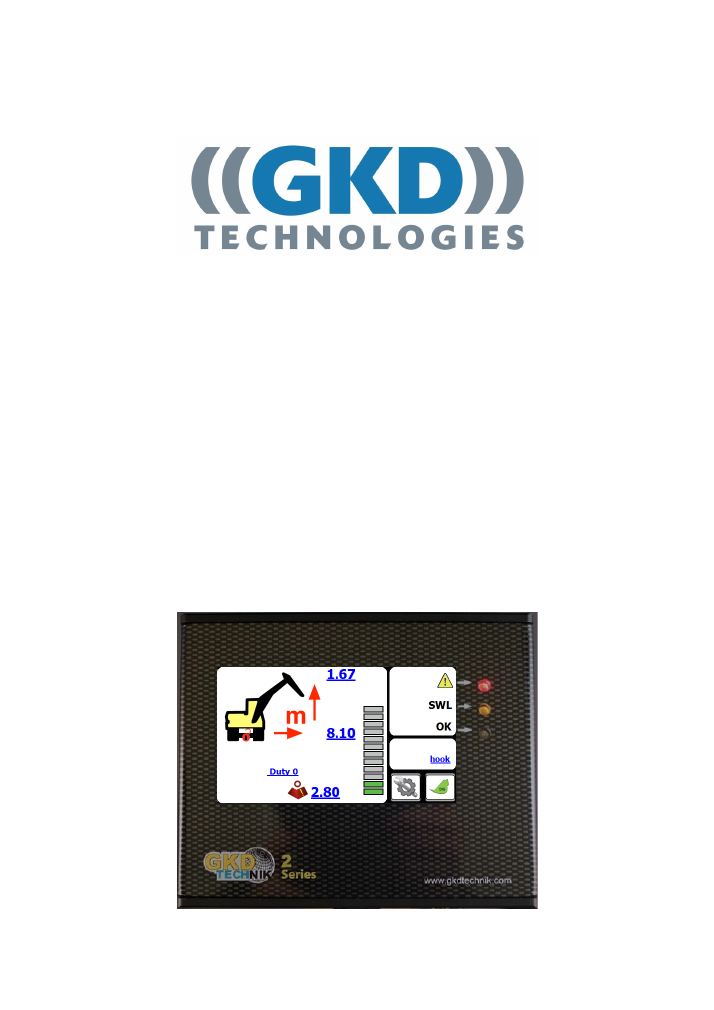
Operation
The 2RCI system is wired to automatically start whenever the machine is started. There is no operator
ON/OFF control. At switch on the system will initially show a blank screen and the green LED on the front
panel will blink. Once self tests are complete the indicator screen will illuminate. The system will
automatically start in the lift mode.
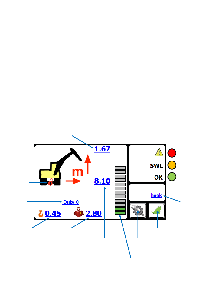
Front Screen
Bucket Pin Height
Axle Lock
Indicator
Bucket Pin Radius
Load on Hook
Lift Status Bar
Duty
Indicator
Rated Capacity
Mode Button
Dig Mode Button
Power LED
(System OK)
Overload LED
(or system fault)
Approach LED
Current Lifting
Point
5
GKD Technik Ltd
M2000001
Lifting Operation
In lifting mode the 2RCI system displays the current radius and height of the lifting point and the related
maximum rated capacity. The status graph shows the current load relative to the maximum. The red and
amber LEDs on the front panel provide an indication of approach to and exceeding of rated capacity. An
external and internal (where fitted) sounder will also indicate the current status.
Lifting Duties
The 2RCI system may be calibrated to provide lifting capacity ratings for different configurations of
machine. The switching between duties may be automatic via external limit switches or automatically
selected from machine slew position (slew module option only), or manual via the
‘
MODE
’
screen.
The lifting duty number is shown on the front screen.
Selection of Lift Attachment
-
Options
2RCI supports the use of Forks or Demountable Jibs for lifting and height limiting purposes.
In the standard configuration, only the Bucket Pin is defined as the lift attachment, and no other selection
is available unless they have been enabled and set up within the system calibration menus.
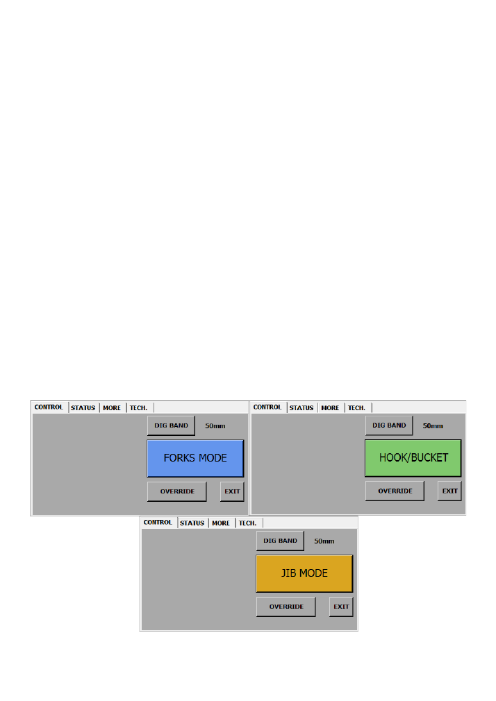
Manual Lifting Duty Selection (Jib and Forks Versions)
Selection of the lifting mode is made from the MODE screen. Access to this screen is by pressing the
MODE button on the front screen. There are three available lift configurations. The mode is selected by
repeatedly pressing the coloured lift duty button.
6
GKD Technik Ltd
M2000001
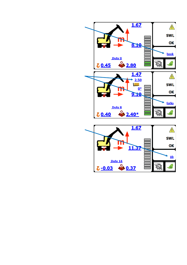
Lifting Mode
Hook/Bucket duty
This is the standard excavator lifting configuration.
The radius and height are measured to the bucket
pin on the stick and all calculations of rated capacity
are referenced to this position. The front screen of
the indicator will show a duty status
‘
hook
’.
Jib duty
When the extension jib is fitted to the machine this
duty adjusts the lifting capacity to be measured at
the end of the jib. The front screen will show a
‘
JIB
’
status. In addition there is a warning if the hydraulic
pressure is exceeded in the jib cylinder.
Forks Duty
When the forks are attached to the machine the
system will provide a height and radius offset
to the position of the load on the forks. As well as
showing a duty status of
’
forks
’.
In addition there is
an automatic height limit applied to the fork mode.
This height limit is pre
-
set at 2.5m (the screenshot
to the right shows the status and height limit).
7
GKD Technik Ltd
M2000001
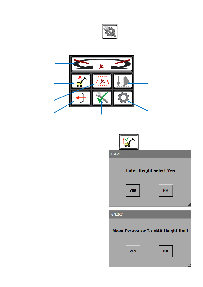
Mode Menu
From the main screen, press on the Mode button.
The following window should appear:
Set and Cancel
Height Limit
Set and Cancel
Virtual Walls
Exit to Main Screen
Test Button
To Settings Menu
Set and Cancel
Slew Limits
Dig Mode settings
Setting a Height Limit
From the Mode Menu, press on the
“
Height Limit
”
button.
The system will ask if you want to enter the maximum
height limit with the keyboard. Pressing
“
YES
”
will bring
up a keyboard screen. Enter the height in metres and
press OK. [Pressing exit without entering data will
switch off the limit].
Pressing
“
NO
”
will allow the height to be set by moving
the machine to the maximum height.
Press
“
YES
”
when the machine is in the correct
position. NOTE this screen will timeout if not selected
within 10 seconds.
8
GKD Technik Ltd
M2000001
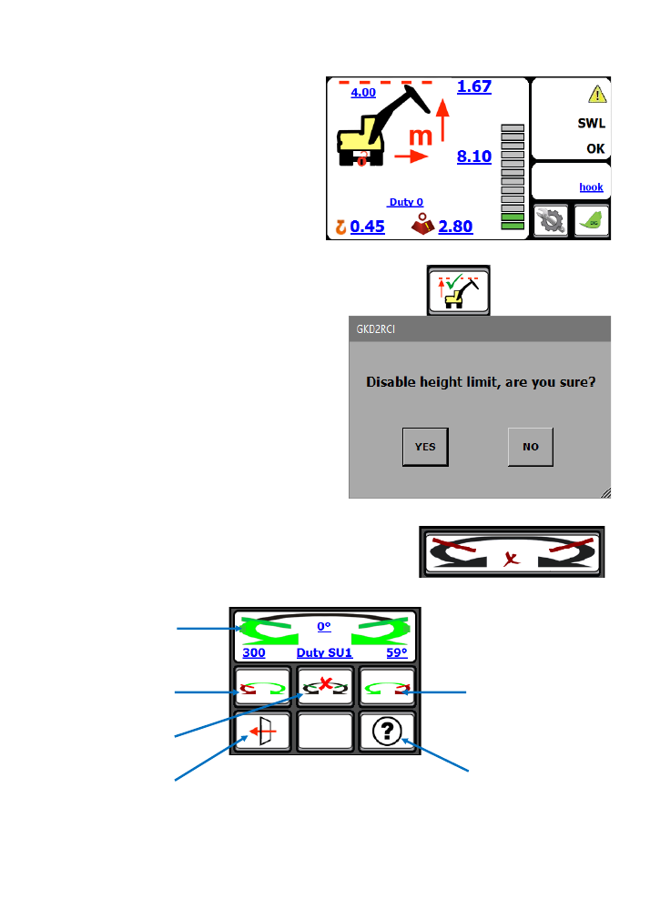
Height Limit continued...
When there is a height limit set, this will be shown
on the main screen.
If the height is exceeded then the internal buzzer
will sound and the boom lift will be cut (if an
optional motion valve is fitted).
Cancelling a Height Limit
Access the Mode Menu and press on the
“
Height Limit
”
button.
The 2RCI will prompt the operator to confirm that the
height limit should be disabled, as shown here. Pressing
“
YES
”
will disable the height limit function.
Normal operation will be resumed but with no height
limit active.
Setting a Slew Limit
From the Mode Menu, press on the
“
Set/Cancel Slew Limit
”
button.
The 2RCI will then show you this screen:
Set left Limit
Enable/Disable
limits
Exit to Main Screen
Help Menu
Current set
Slew Limits
Set right limit
To set slew limits, slew the machine left to required position and press the
“
Set Left Limit
”
button.
Then slew the machine right to the required position and press the
“
Set Right Limit
”
button. Return to
the operator screen and check that the limits are working correctly by slewing the machine left and right
until the limits are reached.
9
GKD Technik Ltd
M2000001
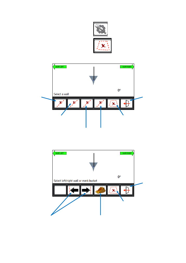
Virtual Walls
You should be shown the screen below:
Set Virtual Wall 1
Enable/Disable all limits
Exit to Main Screen
From the main screen, press on the Mode button:
Then press on the Virtual Wall button:
Set Virtual Wall 2
Set Virtual Wall 4
Set Virtual Wall 3
Pressing on any of the
“
Set Virtual Wall
”
buttons will display the following screen:
Enable/Disable all limits
Exit to Main Screen
Set a virtual wall by moving the bucket or tool to 2
different points near the machine. The system will
then connect these points with a
‘
virtual wall
’
which will then become the limit.
Set a left or right virtual wall which will be parallel
with the tracks or wheels of the machine.
This is entered as a distance, in metres, from the
centre of the machine.
10
GKD Technik Ltd
M2000001
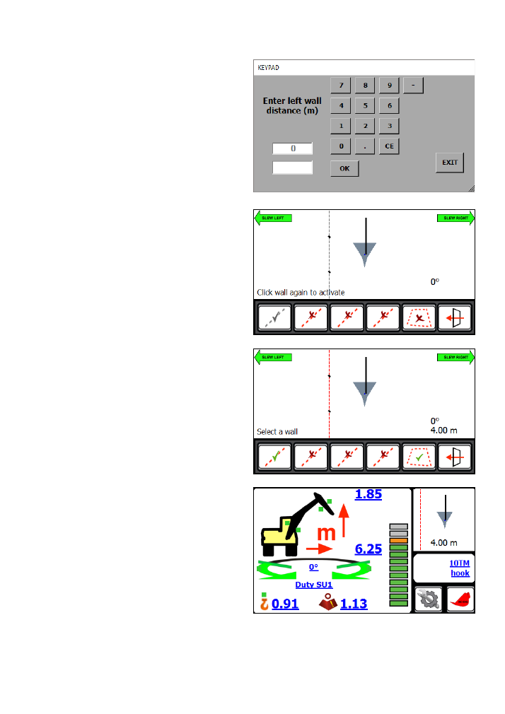
Virtual Walls continued...
Setting a virtual wall by entering a distance
Press on the
“
Set Virtual Wall
1”
button.
Then press on the
“
Left Wall
”
button.
A keypad will open for you to enter the distance to
the left wall, in metres.
Enter the distance and press ok.
The screen should now change back to one similar
to that pictured to the right.
The
“
Set Virtual Wall
1”
button will now be greyed
out. Pressing on this button will activate the virtual
wall and the button will change to indicate that the
virtual wall is not active.
The screen pictured to the right, shows a virtual wall
set and active.
The screen pictured to the right, shows the main
operator screen once the virtual wall has been set
and activated.
The top right corner of the display will show where
the virtual wall is in relation to the machine. It will
also show the distance to the virtual wall from the
machine.
As the machine slews, its position and distance to the wall will be updated automatically.
When the machine reaches the virtual wall, all relevant machine motions will be prevented from
breaching the wall. This includes Boom and Dipper motions.
11
GKD Technik Ltd
M2000001
Virtual Walls continued...
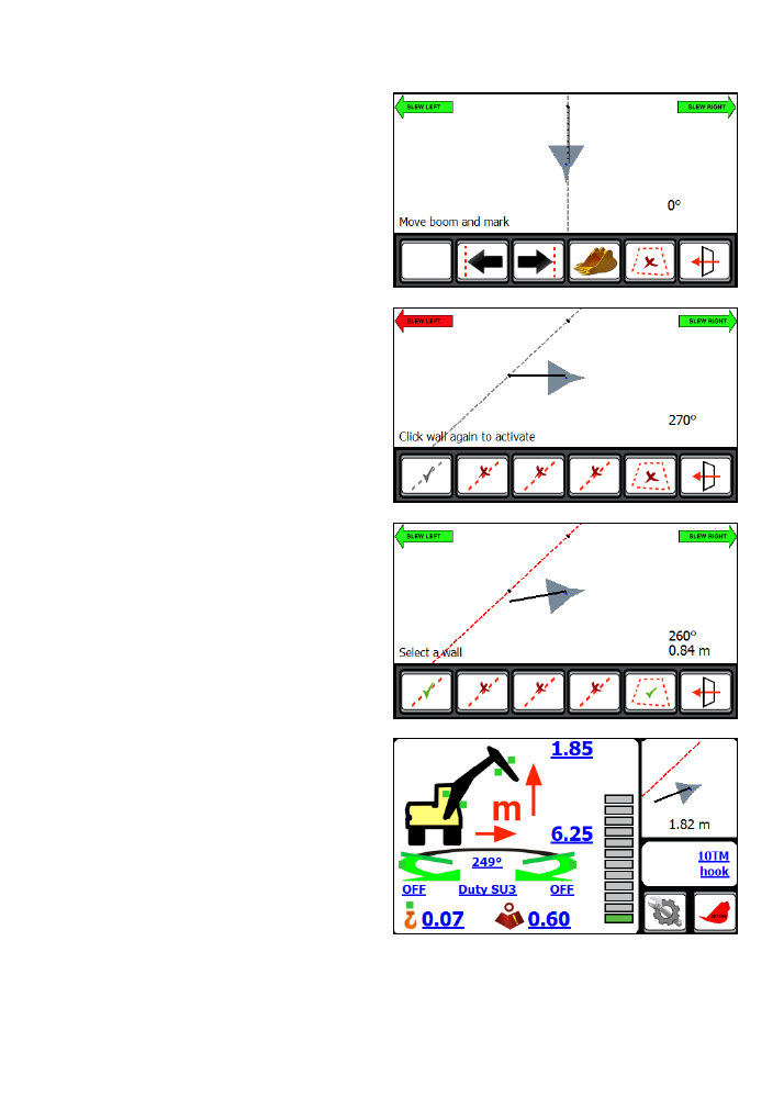
Setting a virtual wall using the bucket
Move the machine and position the bucket where
the first point of the wall is required.
Press on the
“
Bucket
”
button.
The system will log this point as the first point of the
virtual wall.
Slew the machine to move the bucket to the second
position. As the machine moves, you will see the
screen update and create a virtual wall between the
first point and where the bucket is.
Once you have positioned the machine at the
second point, press the
“
Bucket
”
button again.
This will log the second point of the virtual wall.
The
“
Set Virtual Wall
1”
button will now be greyed
out. Pressing on this button will activate the virtual
wall and the button will change to indicate that the
virtual wall is not active.
This method is the same for Virtual Walls 2,3 & 4.
The screen pictured to the right, shows the main
operator screen once the virtual wall has been set
and activated.
The top right corner of the display will show where
the virtual wall is in relation to the machine. It will
also show the distance to the virtual wall from the
machine.
As the machine slews, its position and distance to the wall will be updated automatically.
When the machine reaches the virtual wall, all relevant machine motions will be prevented from
breaching the wall. This includes Boom and Dipper motions.
12
GKD Technik Ltd
M2000001
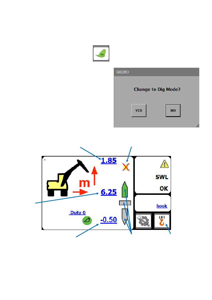
Dig Mode
When the excavator is not being used for lifting operations then the 2RCI should be switched
into dig mode. In dig mode the alarm is muted and any motion cuts (if fitted) will not be activated in the
event of an overload situation. While in dig mode, the 2RCI provides a guide to levelling or trenching.
The 2RCI will prompt the operator to confirm that they
want to switch into Dig Mode.
To enter Dig Mode, press on the dig button.
Pressing
“
YES
”
will switch the 2RCI into dig mode and the main screen should now look like this:
Current Dig Depth
or Target Level
Bucket Pin Height
Bucket Pin
Radius
Target Level Indicator
Alarm silenced icon
Return to Lift Mode
To exit Dig Mode and return to Lifting Mode, press on the
“
Return to Lift Mode
”
button, shown above.
13
GKD Technik Ltd
M2000001
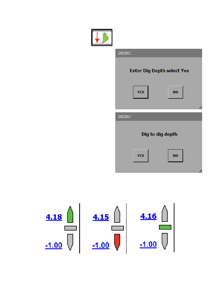
Dig Mode continued...
The system will ask you if you want to enter a depth
using the on screen keypad. Press
“
YES
”
to access the
keypad. Enter a depth that is relative to the base point
of the boom and press enter. Press exit from the
keypad to deselect the dig mode.
Depth Setting
To adjust or set the dig depth, press on the
button which is in the Mode Menu.
Pressing
“
NO
”
will allow the operator to use the
position entry mode.
Place the bucket at the level required and press
“
YES
”
.
The system will now use this position as the target
depth.
When in digging mode the system provides a level indicator. The indicator shows the target level.
There are three states for the indicator, as shown below:
Above Target Level
Below Target Level
On Target Level
NOTE
-
The depth indication is measured to the load point. The orientation of the bucket will affect the
accuracy of the indicator. Moving the machine from one level to another will change the depth of a
trench. Whenever the machine is moved it is recommended that the depth is reset by placing the bucket
on the level previously dug and reset the depth by pressing dig mode,
“
NO
”
and
“
YES
”
to make the new
bucket position to datum.
14
GKD Technik Ltd
M2000001
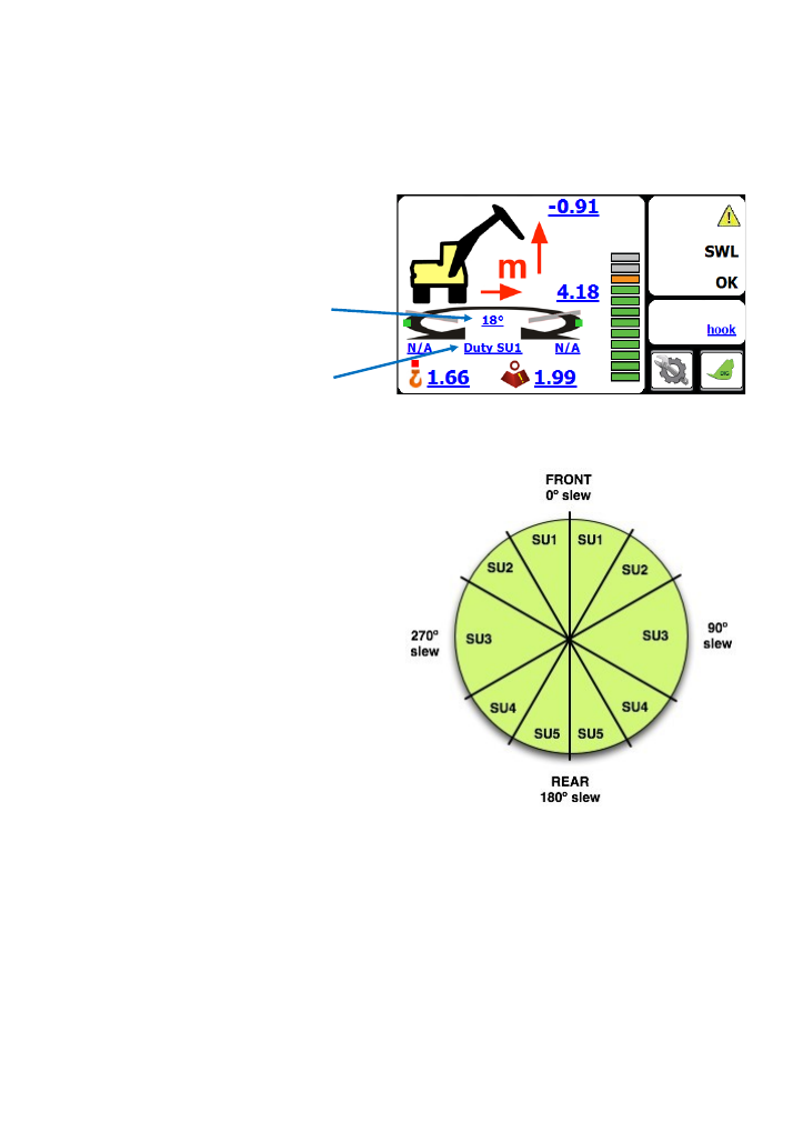
Automatic Slew Based Lifting Duties
The 2RCI system may optionally be equipped with an additional module to monitor the slew position of
the turret relative to the machine undercarriage, and automatically select lift duties based on the slew
position of the turret.
Current duty in use, and the current slew position of
the turret relative to the undercarriage, are
indicated on the 2RCI display.
Current Slew Duty (SU1
-
SU5)
Current slew position of the
turret in degrees (0°
-
360°)
Typically, eight slew
“
duties
”
are available. The duties are named SU1
-
SU5, with each duty having it
’
s
own calibrated
“
tip
”
point for the machine.
As the turret is slewed the appropriate lift duty for
the slew position is automatically selected, and the
lift capacity calculated by the RCI will be adjusted
for the slew position of the machine based on the
duty in use.
Thus, more lift capacity can be attained for the
machine over the front and rear than over the side,
and the machine
’
s lift capability is maximised for
the slew position of the machine.
15
GKD Technik Ltd
M2000001
Full Motion Cut on Overload
The 2RCI can be optionally equipped with an additional I/O module, which enables the 2RCI to control
additional motion cut valves. This makes it possible to offer full intelligent motion cut of boom functions
on overload to prevent the machine from being moved further into an unsafe overload state. All boom
functions that will reduce the lift radius and move the load to a safer position remain enabled.
An indication of boom motion cut status is shown
by a series of colourised dots on the machine
graphic. On motion cut, the dot that symbolises any
hydraulic function that would take the system
further into overload.
In normal operation, these dots will be green.
This indicates that motion are allowed.
When in overload, these dots will turn red. This indicates
that motion is prevented (the motion is cut).
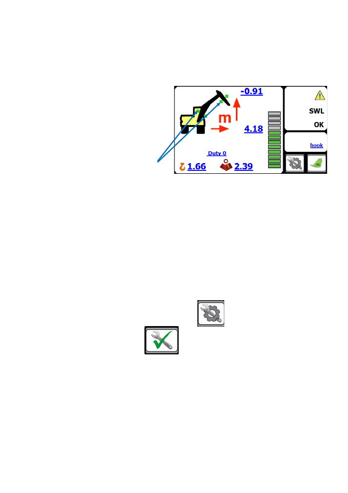
Test Function
Pressing the
“
TEST
”
button will activate the internal and external alarms and operate any motion cut
valves that may be connected for a period of around five seconds. The test button sequence should be
carried out regularly to verify the correct operation of warning devices.
To access the
“
TEST
”
button, first press the
“
MENU
”
button.
Then you can press on the
“
TEST
”
button.
16
GKD Technik Ltd
M2000001
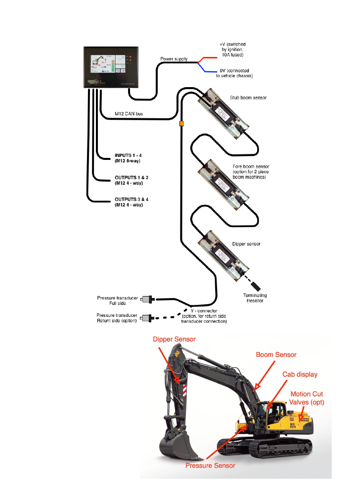
Component Location
Typical locations of 2RCI components
as installed onto a machine are
shown here.
System Layout

17
GKD Technik Ltd
M2000001
Error codes and error diagnosis guide
The system diagnostics continually monitor all of the system components for correct operation. If there is
a problem, the system will show an error message on the display in a red background and if appropriate
sound the alarm. Below is a link to the GKD Knowledge base where you can find definitions of all the error
codes for the 2RCI System.
helpdesk.gkdtechnik.com/kb
Alternatively, contact GKD Technologies on:
+44 (0) 1202 861961
+44 (0) 1202 971971
service@gkdtec.com
www.gkdtec.com
GKD Technik reserve the right to change these instructions in line
with the policy of continuous improvement.