Full Text Searchable PDF User Manual
PART NO. 9380441038
AIR CONDITIONER
INSTALLATION MANUAL
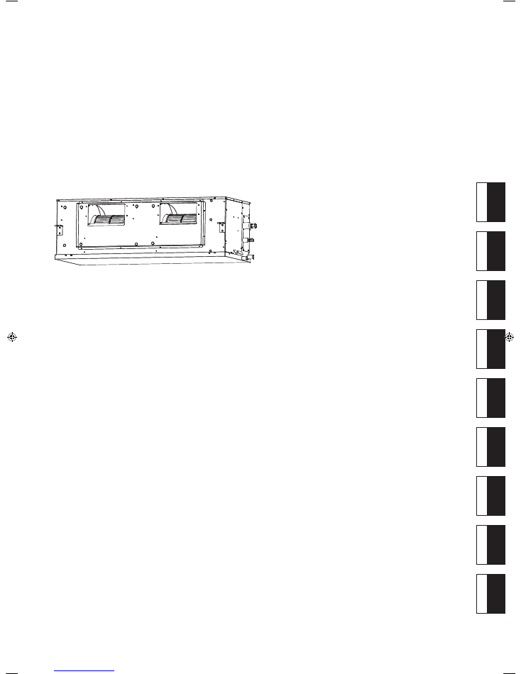
INDOOR UNIT (Duct Type)
For authorized service personnel only.
INSTALLATIONSANLEITUNG
INNENGERÄT (Für Luftkanalsysteme)
Nur für autorisiertes Personal.
MANUEL D'INSTALLATION
UNITÉ INTÉRIEURE (Type conduit)
Pour le personnel agréé uniquement.
MANUAL DE INSTALACIÓN
UNIDAD INTERIOR (Con conductos)
Solo para personal autorizado.
MANUALE D'INSTALLAZIONE
UNITÀ INTERNA (Tipo di condotto)
Ad uso esclusivo del personale autorizzato.
ΕΓΧΕΙΡΙΔΙΟ ΕΓΚΑΤΑΣΤΑΣΗΣ
ΕΣΩΤΕΡΙΚΗ ΜΟΝΑΔΑ (Τύποςαγωγού)
Гια εξουσιοδοτημένο προσωπικό σέρβις.
MANUAL DE INSTALAÇÃO
UNIDADE INTERIOR (Tipo conduta)
Apenas para técnicos autorizados.
РУКОВОДСТВО ПО УСТАНОВКЕ
ВНУТРЕННИЙ МОДУЛЬ (Канального типа)
Для yпoлнoмoчeнного персонала.
KURULUM KILAVUZU
İÇ ÜNİTE (Oluk tipi)
Yetkili servis personeli içindir.
Português
EλληvIkά
Italiano
Español
Français
Deutsch
English
Ру
сс
кий
Türkçe
9380441038_IM.indb 1
28/1/2556 13:44:21
En-1
SAFETY PRECAUTIONS
1
1
Be sure to read this Manual thoroughly before installation.
•
The warnings and precautions indicated in this Manual
•
contain important information pertaining to your safety. Be sure to observe them.
Hand this Manual, together with the Operating Manual, to the customer. Request the
•
customer to keep them on hand for future use, such as for relocating or repairing the unit.
WARNING
This mark indicates procedures which, if improperly performed,
might lead to the death or serious injury of the user.
Request your dealer or a professional installer to install the indoor unit in accordance
with this Installation Manual. An improperly installed unit can cause serious accidents
such as water leakage, electric shock, or fire. If the indoor unit is installed in disregard
of the instructions in the Installation Manual, it will void the manufacturer’s warranty.
Do not turn ON the power until all work has been completed. Turning ON the power
before the work is completed can cause serious accidents such as electric shock or
fire.
If refrigerant leaks while work is being carried out, ventilate the area. If the refrigerant
comes in contact with a flame, it produces a toxic gas.
Installation work must be performed in accordance with national wiring standards by
authorized personnel only.
Do not touch the fins of the heat exchanger. Touching the heat exchanger fins could
result in damage to the fins or personal injury such as skin rupture.
CAUTION
This mark indicates procedures which, if improperly performed,
might possibly result in personal harm to the user, or damage
to property.
Read carefully all security information before use or install the air conditioner.
Do not attempt to install the air conditioner or a part of the air conditioner by yourself.
This unit must be installed by qualified personnel with a capacity certificate for handling
refrigerant fluids. Refer to regulation and laws in use on installation place.
The installation must be carried out in compliance with regulations in force in the place
of installation and the installation instructions of the manufacturer.
This unit is part of a set constituting an air conditioner. It must not be installed alone or
with non-authorized by the manufacturer.
Always use a separate power supply line protected by a circuit breaker opera-ting on all
wires with a distance between contact of 3 mm for this unit.
The unit must be correctly grounded and the supply line must be equipped with a dif-
ferential breaker in order to protect the persons.
The units are not explosion proof and therefore should not be installed in explosive
atmosphere.
Never touch electrical components immediately after the power supply has been turned
off. Electric shock may occur. After turning off the power, always wait 5 minutes before
touching electrical components.
This unit contains no user-serviceable parts. Always consult authorized service person-
nel to repairs.
When moving, consult authorized service personnel for disconnection and installation
of the unit.
This appliance is not intended for use by persons (including children) with reduced
physical, sensory or mental capabilities, or lack of experience and knowledge, unless
they have been given supervision or instruction concerning use of the appliance by a
person responsible for their safety. Children should be supervised to ensure that they do
not play with the appliance.
ABOUT THE UNIT
21
Precautions for using R410A refrigerant
21
1
1
WARNING
Do not introduce any substance other than the prescribed refrigerant into the
refrigeration cycle. If air enters the refrigeration cycle, the pressure in the refrigeration
cycle will become abnormally high and cause the piping to rupture.
If there is a refrigerant leak, make sure that it does not exceed the concentration limit.
If a refrigerant leak exceeds the concentration limit, it can lead to accidents such as
oxygen starvation.
Do not touch refrigerant that has leaked from the refrigerant pipe connections or other
area. Touching the refrigerant directly can cause frostbite.
If a refrigerant leak occurs during operation, immediately vacate the premises and
thoroughly ventilate the area. If the refrigerant comes in contact with a flame, it
produces a toxic gas.
Special tool for R410A
21 21
WARNING
To install a unit that uses R410A refrigerant, use dedicated tools and piping materials
that have been manufactured specifically for R410A use. Because the pressure
of R410A refrigerant is approximately 1.6 times higher than the R22, failure to use
dedicated piping material or improper installation can cause rupture or injury.
Furthermore, it can cause serious accidents such as water leakage, electric shock, or fire.
Tool name
Changes
Gauge manifold
The pressure in the refrigerant system is extremely high
and cannot be measured with a conventional gauge.
To prevent erroneous mixing of other refrigerants,
the diameter of each port has been changed. It is
recommended to use a gauge manifold with a high
pressure display range of –0.1 to 5.3 MPa and a low
pressure display range of –0.1 to 3.8 MPa.
Charging hose
To increase pressure resistance, the hose material and
base size were changed.
(The charging port thread diameter for R410A is 1/2 UNF
20 threads per inch.)
Vacuum pump
A conventional vacuum pump can be used by installing a
vacuum pump adapter.
Be sure that the pump oil does not backflow into the
system. Use one capable for vacuum suction of
–100.7 kPa (5 Torr, –755 mmHg).
Gas leakage detector
Special gas leakage detector for R410A refrigerant.
INSTALLATION MANUAL
PART NO. 9380441038
INDOOR UNIT (Duct Type)
Contents
SAFETY PRECAUTIONS
1.
……………………………………………………………… 1
ABOUT THE UNIT
2
.
………………………………………………………………………… 1
Precautions for using R410A refrigerant
2
.1.
………………………………………… 1
Special tool for R410A
2
.
2
.
……………………………………………………………… 1
Accessories
2
.3.
…………………………………………………………………………
2
Optional parts
2
.4.
………………………………………………………………………
2
INSTALLATION WORK
3.
…………………………………………………………………
2
Selecting an installation location
3.1.
…………………………………………………
2
Installation dimension
3.
2
.
………………………………………………………………
2
Installation the unit
3.3.
………………………………………………………………… 3
PIPE INSTALLATION
4.
…………………………………………………………………… 4
Selecting the pipe material
4.1.
………………………………………………………… 4
Pipe requirement
4.
2
.
…………………………………………………………………… 4
Flare connection (pipe connection)
4.3.
……………………………………………… 4
Installing heat insulation
4.4.
…………………………………………………………… 5
INSTALLING DRAIN PIPES
5.
……………………………………………………………… 5
ELECTRICAL WIRING
6
.
……………………………………………………………………
6
Electrical requirement
6
.1.
………………………………………………………………
6
Wiring method
6
.
2
.
………………………………………………………………………
6
REMOTE CONTROLLER SETTING
7.
…………………………………………………… 7
Installing the remote controller
7.1.
…………………………………………………… 8
Setting the dip switches
7.
2
.
…………………………………………………………… 8
FUNCTION SETTING
8.
…………………………………………………………………… 8
Turning on the power
8.1.
……………………………………………………………… 8
Setting method
8.
2
.
……………………………………………………………………… 8
Function setting
8.3.
…………………………………………………………………… 9
Setting the room temperature detection location
8.4.
…………………………… 10
TEST RUN
9.
……………………………………………………………………………… 10
CHECK LIST
10.
…………………………………………………………………………… 10
SPECIAL INSTALLATION METHODS
11.
……………………………………………… 10
Group control system
11.1.
…………………………………………………………… 10
Fan delay setting
11.
2
.
………………………………………………………………… 11
Dual remote controllers
11.3.
………………………………………………………… 11
OPTIONAL PARTS
1
2
.
…………………………………………………………………… 11
External input and external output
1
2
.1.
……………………………………………… 11
I.R. receiver unit / Remote sensor
1
2
.
2
.
……………………………………………… 1
2
CUSTOMER GUIDANCE
13.
……………………………………………………………… 1
2
ERROR CODES
14.
……………………………………………………………………… 13
9380441038_IM.indb 1
28/1/2556 13:44:21
En-2
Accessories
21 21
WARNING
For installation purposes, be sure to use the parts supplied by the manufacturer or
other prescribed parts.
The use of non-prescribed parts can cause serious accidents such as the unit falling,
water leakage, electric shock, or fire.
The following installation parts are furnished. Use them as required.
•
Keep the Installation Manual in a safe place and do not discard any other accessories
•
until the installation work has been completed.
Name and Shape
Q’ty
Description
Special nut A
(Large flange)
4
For suspending the indoor unit
from ceiling
Special nut A
(small flange)
4
Coupler heat insulation (Large)
1
For indoor side pipe joint
(Gas pipe)
Coupler heat insulation (Small)
1
For indoor side pipe joint
(Liquid pipe)
Cable tie (Large)
4
For fixing the heat insulation
Cable tie (Medium)
4
For fixing the remote controller
cable and connection cable
Cable tie (Small)
1
For fixing the remote controller
cable
Remote controller
1
For Air conditioner operation
Screw
(Flush heads)
2
For installing indoor unit remote
controller
Remote controller cable
1
For connecting the remote
controller
Optional parts
21
4
1
Parts name
Model No.
Summary
Wired remote controller
UTY-RVN*M
For Air conditioner
operation
Wired remote controller
UTY-RNN*M
For Air conditioner
operation
Simple remote controller
UTY-RSN*M
For Air conditioner
operation
Remote sensor
UTY-XSZX
New amenity space can
be offered by installing
the Remote sensor in the
remote controller
External control set
UTD-ECS5A
Use to connect various
peripheral devices and air
conditioner PC board
INSTALLATION WORK
21
Especially, the installation place is very important for the split type air conditioner because
it is very difficult to move from place to place after the first installation.
Selecting an installation location
21
1
1
Decide the mounting position together with the customer as follows.
WARNING
Select installation locations that can properly support the weight of the indoor unit.
Install the units securely so that they do not topple or fall.
CAUTION
Do not install the indoor unit in the following areas:
Area with high salt content, such as at the seaside.
•
It will deteriorate metal parts, causing the parts to fall or the unit to leak water.
Area filled with mineral oil or containing a large amount of splashed oil or steam,
•
such as a kitchen.
It will deteriorate plastic parts, causing the parts to fall or the unit to leak water.
Area that generates substances that adversely affect the equipment, such as sulfuric
•
gas, chlorine gas, acid, or alkali. It will cause the copper pipes and brazed joints to
corrode, which can cause refrigerant leakage.
Area that can cause combustible gas to leak, contains suspended carbon fibers or
•
flammable dust, or volatile inflammables such as paint thinner or gasoline. If gas
leaks and settles around the unit, it can cause a fire.
Area where animals may urinate on the unit or ammonia may be generated.
•
Do not use the unit for special purposes, such as storing food, raising animals, growing
plants, or preserving precision devices or art objects. It can degrade the quality of the
preserved or stored objects.
Do not install where there is the danger of combustible gas leakage.
Do not install the unit near a source of heat, steam, or flammable gas.
Install the unit where drainage does not cause any trouble.
Install the indoor unit, outdoor unit, power supply cable, transmission cable, and remote
control cable at least 1 m away from a television or radio receivers. The purpose of this
is to prevent TV reception interference or radio noise.
(Even if they are installed more than 1 m apart, you could still receive noise under
some signal conditions.)
Install the unit where ambient temperature does not reach 60°C or more.
Take a measure such as ventilation for an environment in which heat is retained.
If children under 10 years old may approach the unit, take preventive measures so that
they cannot reach the unit.
Take precautions to prevent the unit from falling.
Install the indoor unit on a place having a sufficient strength so that it withstands
(1)
against the weight of the indoor unit.
The inlet and outlet ports should not be obstructed; the air should be able to blow all
(
2
)
over the room.
Leave the space required to service the air conditioner.
(3)
Install the unit where connection to the outdoor unit is easy.
(4)
Install the unit where the connection pipe can be easily installed.
(5)
Install the unit where the drain pipe can be easily installed.
(
6
)
Install the unit where noise and vibrations are not amplified.
(7)
Take servicing, etc., into consideration and leave the spaces. Also install the unit where
(8)
the filter can be removed.
Do not install the unit where it will be exposed to direct sunlight.
(9)
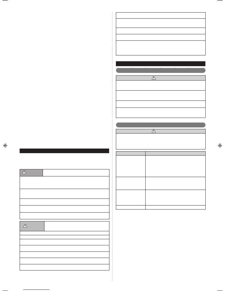
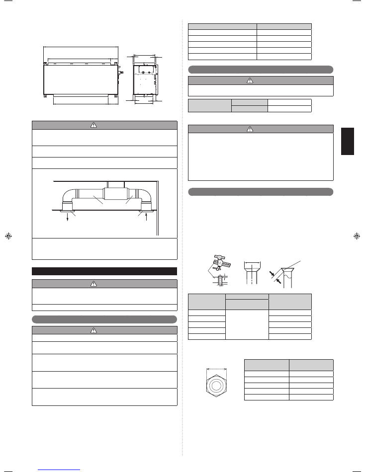
Installation dimension
21 21
Installation by which service space is made on top of the unit
21 21
1
1
(recommended)
Install the unit away from the ceiling by 350 mm or more.
350
or
more
2500 or more
(When no ceiling)
Service
space
Unit : mm
Service access
500 or more
Floor
9380441038_IM.indb 2
28/1/2556 13:44:24
En-3
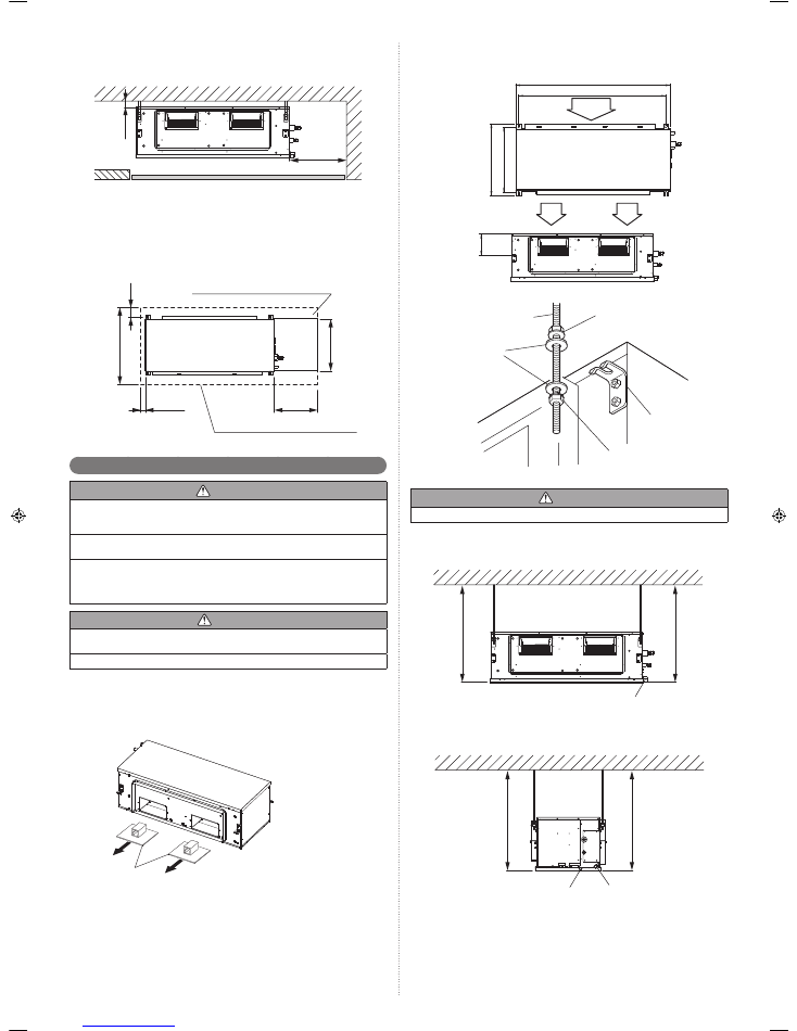
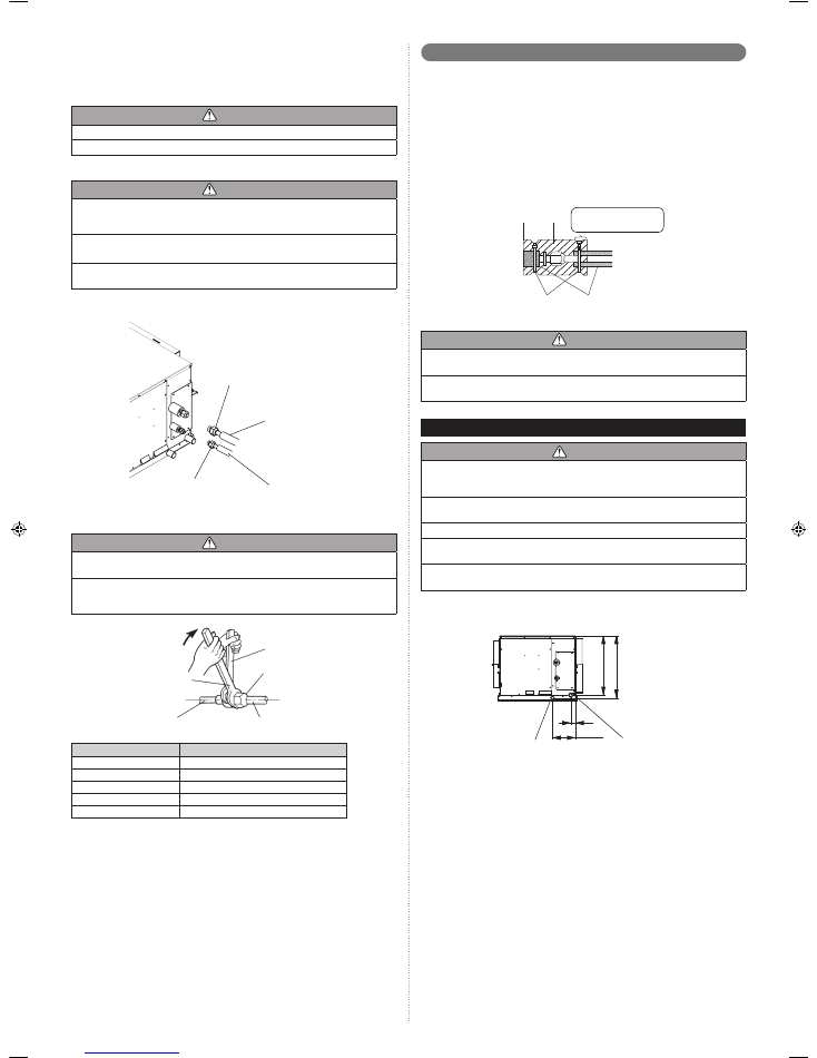
Installing hangers
21 21 21
Suspend the indoor unit by referring to the following figures.
Inlet port
Outlet port
AIR
AIR
AIR
1260
1192
526
586
Unit : mm
181
Hanging bolt M10
(Field supply)
Special nut A
(Accessories)
Washer
(Field supply)
Hanger
Special nut B
(Accessories)
CAUTION
Fasten the unit securely with special nuts A and B.
Leveling
21 21 21
Use the procedure in the following figure to adjust the levelness.
B
A
Level meter
Safty drain port
(Front)
The side of the unit that holds the drain port A should be slightly lower than the opposite
side of the unit B. The slant should allow from 0 to 20 mm of difference between A and B.
B
A
(Side)
Level meter
Main drain port
Safty drain port
The side of the unit that holds the drain port A should be slightly lower than the opposite
side of the unit B. The slant should allow from 0 to 10 mm of difference between A and B.
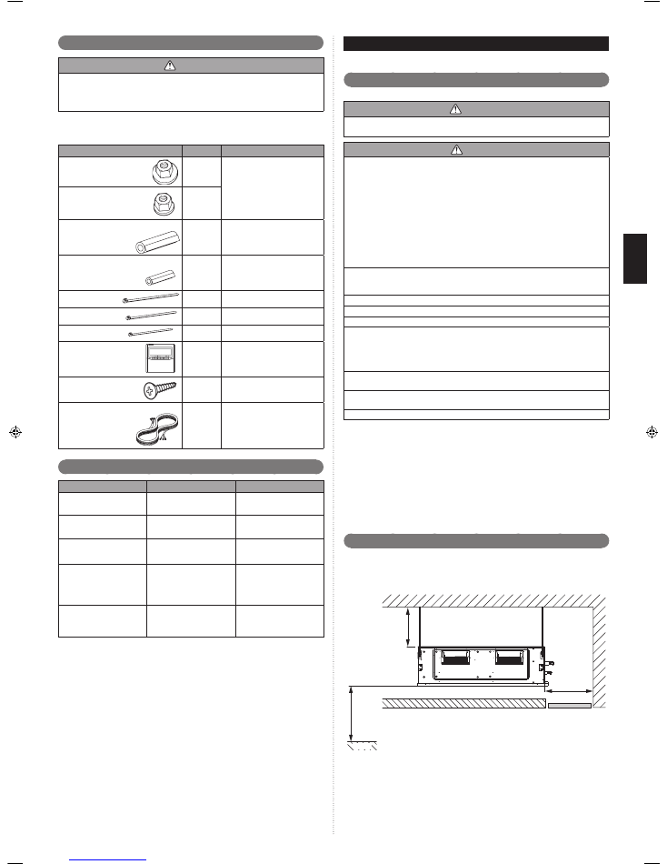
Installation by which service is carried out from the bottom of the
21 21 21
unit
20 or
more
Service
space
Unit : mm
Service access
500 or more
(For maintenance)
21 21 21
Maintenance work of the control box is possible with the Service access of the
(1)
measurement shown in the figure.
If maintenance work is to be done from the bottom side, the Service access needs to
(
2
)
be larger than the outside dimension of the indoor unit.
If maintenance work is to be done from the top, keep the space of the more than
(3)
450 mm between the indoor unit and ceiling.
800
or
more
500
or
more
30 or
more
500 or
more
200 or
more
Service access size of 3.2.1
Drain pan
Unit : mm
Service access size of 3.2.2
Installation the unit
21 21
WARNING
Install the air conditioner in a location which can withstand a load of at least 5 times
the weight of the main unit and which will not amplify sound or vibration. If the
installation location is not strong enough, the indoor unit may fall and cause injuries.
If the job is done with the panel frame only, there is a risk that the unit will come loose.
Please take care.
Carrying in and installation of the unit should be performed by a sufficient number
of people and with sufficient equipment that is adequate for the weight of the unit.
Performing such work by an insufficient number of people or with inadequate
equipment could result in dropping of the unit or personal injury.
CAUTION
Confirm the directions of the air intake and outlet before installing the unit.
The unit takes in air from the evaporator side, and expels it from the fan side.
For installation, refer to the technical data.
Conveyance method
21 21
1
1
Leave the packing materials on until the unit is at the installation site.
•
Remove the packing hardware and dispose of it.
•
Be careful not to dispose the accessories.
•
Unit is packed upside down.
Fan holder (2 locations) Pull them out towards you.
9380441038_IM.indb 3
28/1/2556 13:44:32
En-4
Mounting the duct
21 21
4
1
Follow the procedure in the following figure to install the ducts.
351
19
14
30
304
49
1260
1062
106
152
921
Inlet port flange
*Spacing between flange and safety drain pan.
Outlet port flange
Unit : mm
CAUTION
To prevent people from touching the parts inside the unit, be sure to install grilles on
the inlet and outlet ports. The grilles must be designed in such a way that cannot be
removed without tools.
Set the external static pressure between 60 and 260Pa and set the appropriate static
pressure mode. (Refer to 8.3 Function setting)
If an intake duct is installed, take care not to damage the temperature sensor (the
temperature sensor is attached to the intake port flange).
Install the air inlet grille for air circulation. The correct temperature can not be
detected.
Unit
Outlet Grille
(Field supply)
Inlet Grille
(Field supply)
(Room)
Duct
(Field supply)
When connecting the duct, perform duct-insulation that is appropriate for the installing
environment.
Inappropriate insulation work may cause condensation on the surface of the insulating
material, and may lead condensation drip.
PIPE INSTALLATION
4
1
CAUTION
Be more careful that foreign matter (oil, water, etc.) does not enter the piping than with
refrigerant R410A models. Also, when storing the piping, securely seal the openings
by pinching, taping, etc.
While welding the pipes, be sure to blow dry nitrogen gas through them.
Selecting the pipe material
4
1
1
1
CAUTION
Do not use existing pipes.
Use pipes that have clean external and internal sides without any contamination which
may cause trouble during use, such as sulfur, oxide, dust, cutting waste, oil, or water.
It is necessary to use seamless copper pipes.
Material : Phosphor deoxidized seamless copper pipes
It is desirable that the amount of residual oil is less than 40 mg/10 m.
Do not use copper pipes that have a collapsed, deformed, or discolored portion
(especially on the interior surface). Otherwise, the expansion valve or capillary tube may
become blocked with contaminants.
Improper pipe selection will degrade performance. As an air conditioner using R410A
incurs pressure higher than when using conventional refrigerant, it is necessary to
choose adequate materials.
Thicknesses of copper pipes used with R410A are as shown in the table.
•
Never use copper pipes thinner than those indicated in the table even if they are available
•
on the market.
Pipe outside diameter [mm (in.)]
Thickness [mm]
6.35 (1/4)
0.8
9.52 (3/8)
0.8
12.70 (1/2)
0.8
15.88 (5/8)
1.0
19.05 (3/4)
1.2
Pipe requirement
4
1 21
CAUTION
Refer to the Installation Manual of the outdoor unit for description of the length of
connecting pipe or for difference of its elevation.
Diameter [mm (in.)]
Liquid
9.52 (3/8)
Gas
15.88 (5/8)
Use pipe with water-resistant heat insulation.
•
CAUTION
Install heat insulation around both the gas and liquid pipes. Failure to do so may
cause water leaks.
Use heat insulation with heat resistance above 120 °C. (Reverse cycle model only)
In addition, if the humidity level at the installation location of the refrigerant piping is
expected to exceed 70 %, install heat insulation around the refrigerant piping.
If the expected humidity level is 70-80 %, use heat insulation that is 15 mm or thicker
and if the expected humidity exceeds 80 %, use heat insulation that is 20 mm or
thicker. If heat insulation is used that is not as thick as specified, condensation may
form on the surface of the insulation.
In addition, use heat insulation with heat conductivity of 0.045 W/(m·K) or less (at 20 °C).
Flare connection (pipe connection)
4
1 21
Flaring
4
1 21
1
1
Use special pipe cutter and flare tool exclusive for R410A.
•
Cut the connection pipe to the necessary length with a pipe cutter.
(1)
Hold the pipe downward so that cuttings will not enter the pipe and remove any burrs.
(
2
)
Insert the flare nut (always use the flare nut attached to the indoor and outdoor units
(3)
respectively) onto the pipe and perform the flare processing with a flare tool. Use the
special R410A flare tool, or the conventional flare tool. Leakage of refrigerant may
result if other flare nuts are used.
Protect the pipes by pinching them or with tape to prevent dust, dirt, or water from
(4)
entering the pipes.
Check if [L] is flared uniformly
and is not cracked or scratched.
Pipe
Die
B
L
A
Pipe outside
diameter
[mm (in.)]
Dimension A [mm]
Dimension B
-
0
0.4
[mm]
F
lare tool for R410A,
clutch type
6.35 (1/4)
0 to 0.5
9.1
9.52 (3/8)
13.2
12.70 (1/2)
16.6
15.88 (5/8)
19.7
19.05 (3/4)
24.0
When using conventional flare tools to flare R410A pipes, the dimension A should be
approximately 0.5 mm more than indicated in the table (for flaring with R410A flare tools) to
achieve the specified flaring. Use a thickness gauge to measure the dimension A.
Pipe outside
diameter [mm (in.)]
Width across flats
of Flare nut [mm]
6.35 (1/4)
17
9.52 (3/8)
22
12.70 (1/2)
26
15.88 (5/8)
29
19.05 (3/4)
36
Width across
flats
9380441038_IM.indb 4
28/1/2556 13:44:34
En-5
Bending pipes
4
1 21 21
If pipes are shaped by hand, be careful not to collapse them.
•
Do not bend the pipes in an angle more than 90°.
•
When pipes are repeatedly bend or stretched, the material will harden, making it difficult
•
to bend or stretch them any more.
Do not bend or stretch the pipes more than 3 times.
•
CAUTION
To prevent breaking of the pipe, avoid sharp bends.
If the pipe is bent repeatedly at the same place, it will break.
Pipe connection
4
1 21 21
CAUTION
Be sure to apply the pipe against the port on the indoor unit correctly. If the centering
is improper, the flare nut cannot be tightened smoothly. If the flare nut is forced to turn,
the threads will be damaged.
Do not remove the flare nut from the indoor unit pipe until immediately before
connecting the connection pipe.
Do not use mineral oil on flared part. Prevent mineral oil from getting into the system
as this would reduce the lifetime of the units.
Detach the caps and plugs from the pipes.
(1)
Centering the pipe against port on the indoor unit, turn the flare nut with your hand.
(
2
)
Connection pipe
(small)
Flare nut
Flare nut
Connection pipe
(large)
When the flare nut is tightened properly by your hand, hold the body side coupling with
(3)
a separate spanner, then tighten with a torque wrench. (See the table below for the
flare nut tightening torques.)
CAUTION
Hold the torque wrench at its grip, keeping it in the right angle with the pipe, in order to
tighten the flare nut correctly.
Tighten the flare nuts with a torque wrench using the specified tightening method.
Otherwise, the flare nuts could break after a prolonged period, causing refrigerant to
leak and generate a hazardous gas if the refrigerant comes into contact with a flame.
Tighten with 2 wrenches.
Connection pipe
Torque wrench
Indoor unit pipe
(Body side)
Flare nut
Holding Wrench
Flare nut [mm (in.)]
Tightening torque [N·m (kgf·cm)]
6.35 (1/4) dia.
16 to 18 (160 to 180)
9.52 (3/8) dia.
32 to 42 (320 to 420)
12.70 (1/2) dia.
49 to 61 (490 to 610)
15.88 (5/8) dia.
63 to 75 (630 to 750)
19.05 (3/4) dia.
90 to 110 (900 to 1,100)
Installing heat insulation
4
1
4
1
Install the heat insulation material after performing a refrigerant leak check (see the
Installation Manual for the outdoor unit for details).
COUPLER HEAT INSULATION
4
1
4
1
1
1
Insulate with the coupler heat insulation (Accessories) around the gas pipe and liquid pipe
•
at indoor unit.
After installing the coupler heat insulation, wrap both ends with vinyl tape so that there is
•
no gap.
After affi xing the coupler heat insulation, secure it with 2 cable tie (large), one on each
•
end of the insulation.
Make sure that the cable tie overlap the heat insulation pipe.
•
Heat insulation
Coupler heat
insulation
(Accessories)
Cover this portion with
heat insulation.
Cable tie (Large)
(Accessories)
CAUTION
After checking for gas leaks (refer to the Installation Manual of the outdoor unit),
perform this section.
Install heat insulation around both the large (gas) and small (liquid) pipes. Failure to
do so may cause water leaks.
INSTALLING DRAIN PIPES
5
1
CAUTION
Install the drain pipe in accordance with the instructions in this Installation Manual and
keep the area warm enough to prevent condensation. Problems with the piping may
lead to water leaks.
This UNIT has drain ports in 2 locations. Follow the procedure in the figure to connect
drain pipes to each of them.
Be sure to properly insulate the drain pipes.
The position of the installed drain pipe should have a downward gradient of 1/100 or
more.
Do not connect the drain pipe in which ammonia or other types of gas affecting the
unit is generated.
Install the drain pipes according to the measurements given in the following figure.
Flange positions for connecting the drain pipes
Safty drain port
Φ25.4 (O.D.)
Main drain port
Φ25.4 (O.D.)
Unit : mm
29
148
382
400
9380441038_IM.indb 5
28/1/2556 13:44:36
En-6
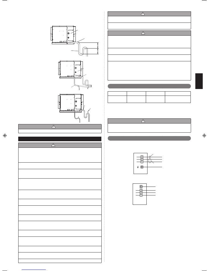
INSTALL THE DRAIN PIPE
•
Use general hard polyvinyl chloride pipe (VP25) and connect it with adhesive (polyvinyl
chloride) so that there is no leakage. Do not perform air bleeding.
Main drain pipe
(1)
Provide one trap on the
main drain pipe near the
indoor unit.
Unit
Drain pipe
Trap
H
1
=100 mm (Approx.)
H
2
pt=50~100 mm
H
2
H
1
Safety drain
(
2
)
There is no need to provide a trap
for the safety drain pipe.
If the safety drain pipe is
connected to the main drain pipe,
make the connection below the
trap on the main drain pipe
Unit
Drain pipe
Main
Safety
Make sure that drain pipe is installed
•
without rises.
Do not perform air bleeding.
•
Rise
Air bleeding
Rise
PROHIBITED
CAUTION
Make sure the drain water is properly drained.
ELECTRICAL WIRING
6
1
WARNING
Electrical work must be performed in accordance with this Manual by a person
certified under the national or regional regulations. Be sure to use a dedicated circuit
for the unit.
An insufficient power supply circuit or improperly performed electrical work can cause
serious accidents such as electric shock or fire.
Before starting work, check that power is not being supplied to the indoor unit and
outdoor unit.
Use the included connection cables and power cables or ones specified by the
manufacturer. Improper connections, insufficient insulation, or exceeding the allowable
current can cause electric shock or fire.
For wiring, use the prescribed type of cables, connect them securely, making sure
that there are no external forces of the cables applied to the terminal connections.
Improperly connected or secured cables can cause serious accidents such as
overheating the terminals, electric shock, or fire.
Do not modify the power cables, use extension cables, or use any branches in the
wiring. Improper connections, insufficient insulation, or exceeding the allowable
current can cause electric shock or fire.
Match the terminal board numbers and connection cable colors with those of the
outdoor unit. Erroneous wiring may cause burning of the electric parts.
Securely connect the connection cables to the terminal board. In addition, secure the
cables with wiring holders. Improper connections, either in the wiring or at the ends of
the wiring, can cause a malfunction, electric shock, or fire.
Always fasten the outside covering of the connection cable with the cable clamp. (If
the insulator is chafed, electric leakage may occur.)
Securely install the electrical box cover on the unit. An improperly installed electrical
box cover can cause serious accidents such as electric shock or fire through exposure
to dust or water.
Install sleeves into any holes made in the walls for wiring. Otherwise, a short circuit
could result.
Install a ground leakage breaker. In addition, install the ground leakage breaker so
that the entire AC main power supply is cut off at the same time. Otherwise, electric
shock or fire could result.
Install a ground leakage breaker.
If a ground leakage breaker is not installed, it may cause electric shock or fire.
Always connect the earth (ground) cable.
Improper earthing (grounding) work can cause electric shocks.
Install the remote control cables so as not to be direct touched with your hand.
WARNING
Perform wiring work in accordance with standards so that the air conditioner can be
operated safely and positively.
Connect the connection cable firmly to the terminal board. Imperfect installation may
cause a fire.
CAUTION
Ground the unit.
Do not connect the earth (ground) cable to a gas pipe, water pipe, lightning rod, or a
telephone earth (ground) cable.
Improper earthing (grounding) may cause electric shock.
Do not connect power supply cables to the transmission or remote control terminals,
as this will damage the product.
Never bundle the power supply cable and transmission cable together. Bundling these
cables together will cause miss operation.
When handling PCB, static electricity charged in the body may cause malfunction of
the PCB. Follow the cautions below:
Establish a ground for the indoor and outdoor units and peripheral devices.
•
Cut power (breaker) off.
•
Touch metal part of the indoor and outdoor units for more than 10 seconds to
•
discharge static electricity charged in the body.
Do not touch terminals of parts and patterns implemented on PCB.
•
Electrical requirement
6
1
1
1
Cable
Cable size (mm
2
)
Type
Remarks
Connection cable
1.5 (MIN.)
Type 60245 IEC57
3Cable+Earth (Ground),
1φ230V
Max. Cable Length: Limit voltage drop to less than 2%. Increase cable gauge if voltage
drop is 2% or more.
Perform all electrical work according to the standard.
•
Install circuit breakers, which have the terminal spacing of more than 3 mm, in a place of
•
near the indoor unit and outdoor unit.
CAUTION
Be sure to execute the electrical work according to the Laws of each country and the
Installation Instructions. In addition, be sure to set as exclusive line and use the rated
voltage and circuit breaker.
Wiring method
6
1 21
Connection diagrams
6
1 21
1
1
Connection cable (to outdoor unit)
•
Control line
Power line
Indoor unit
side
Wired remote controller cable
•
*
Indoor unit
side
White
Red
Black
*Gound the remote controller if it has a earth (ground) wire.
9380441038_IM.indb 6
28/1/2556 13:44:39
En-7
Connection cable preparation
6
1 21 21
Earth (ground) wire
Power supply cable
or connection cable
Keep the earth (ground) wire longer than the other wires.
• Use a 4-core wire cable.
30 mm
40 mm or more
How to connect wiring to the terminals.
(For strand wiring)
Use crimp-type terminals with insulating sleeves as shown in the figure below to
(1)
connect to the terminal block.
Securely crimp the crimp-type terminals to the wires using an appropriate tool so that
(
2
)
the wires do not come loose.
Strip 10 mm
Crimp-type
terminal
Sleeve
Use the specified wires, connect them securely, and fasten them so that there is no
(3)
stress placed on the terminals.
Use an appropriate screwdriver to tighten the terminal screws.
(4)
Do not use a screwdriver that is too small, otherwise, the screw heads may be
damaged and prevent the screws from being properly tightened.
Do not tighten the terminal screws too much, otherwise, the screws may break.
(5)
See the table below for the terminal screw tightening torques.
(
6
)
WARNING
Use crimp-type terminals and tighten the terminal screws to the specified torques,
otherwise, abnormal overheating may be produced and possibly cause serious
damage inside the unit.
Tightening torque [N·m (kgf·cm)]
M4 screw
1.2 to 1.8 (12 to 18)
M5 screw
2.0 to 3.0 (20 to 30)
Screw with
special washer
Crimp-type
terminal
Terminal blocks
Wire
Wire
Screw with
special
washer
Crimp-type
terminal
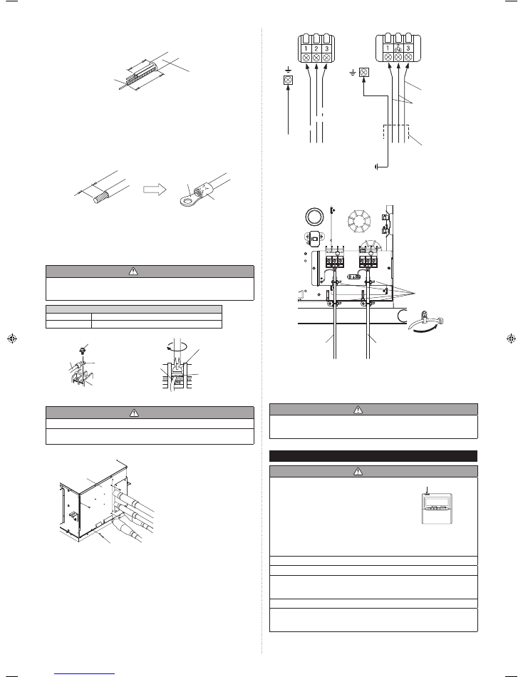
Connection wiring
6
1 21 21
CAUTION
Use care not to mistake the power supply cable and connection wires when installing.
Install so that the wires for the remote controller will not come in contact with other
connection wires.
(1) Remove the control box cover and install each connection wire.
Control box
cover
Loosen the screws.
(4 locations)
Control line
Connection cable
Power line
Outdoor unit
Earth (ground)
Black
White
Red
Remote
controller
*Earth
(ground)
wire
*Ground the remote controller if it has a earth (ground) wire.
(2)
After wiring is complete, secure the remote controller cable, connection cable, and
power supply cable with the cable clamps.
Connection cable
(to outdoor unit)
Remote controller
cable
Cable tie (Medium)
(Accessory)
Control box
(3) Seal the cable outlet or other gaps with putty to prevent dew condensation or insect
from entering the electric control box.
(4) Install the control box cover.
CAUTION
Do not bundle the remote controller cable, or wire the remote controller cable in
parallel, with the indoor unit connection wire (to the outdoor unit) and the power supply
cable. It may cause erroneous operation.
REMOTE CONTROLLER SETTING
7
1
CAUTION
When using the temperature sensor of remote controller,
be sure to meet the following location requirements for
installation of the remote controller in order to detect the
room temperature correctly. If the remote controller is
installed in an improper location, troubles such as “the
room does not become cool or warm” may occur even
though there is no problem in the air conditioner.
Temperature sensor
A location where the average room temperature can be detected.
•
A location that is not directly exposed to the air blown out of the indoor unit.
•
A location that is not exposed to direct sunlight.
•
A location that is not affected by any heat source.
•
Do not touch the remote controller PC board and PC board parts directly with your hands.
Install the remote controller wires so as not to be direct touched with your hand.
Do not wire the remote controller cable and the bus wire together with or parallel to
the connection cables, transmission cables, and power supply cables of the indoor
and outdoor units. It may cause erroneous operation.
When installing the bus wire near a source of electromagnetic waves, use shielded wire.
Do not set the DIP switches, either on the air conditioner or the remote controller, in
any way other than indicated in this manual or the manual that is supplied with the air
conditioner. Doing so may result in an accident.
9380441038_IM.indb 7
28/1/2556 13:44:40
En-8
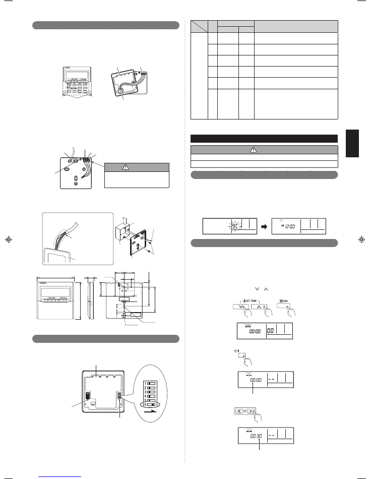
Installing the remote controller
7
1
1
1
Open the operation panel on the front of the remote controller, remove the 2 screws
indicated in the following figure, and then remove the front case of the remote controller.
When installing the remote controller, remove the connector from the front case. The wires
may break if the connector is not removed and the front case hangs down.
When installing the front case, connect the connector to the front case.
Screws
Connector
Front case
(back side) Rear case
When remote controller cable is embedded
•
Embed the remote controller cable and box.
(1)
Pass the remote controller cable through the hole in the rear case and connect the
(
2
)
remote controller cable to the remote controller terminal blocks specified in figure.
Clamp the remote controller cable sheath with the cable tie as shown in figure.
(3)
Cut off the excess cable tie.
(4)
Install the rear case to the wall, box, etc., with 2 screws figure.
(5)
1. R (Red)
2. W (White)
3. B (Black)
Hole
Cable tie
(Small)
CAUTION
When connecting the remote
controller wires, do not overtighten
the screws.
Seal the cable outlet with putty to prevent dew condensation or insect from entering the box.
[Example]
•
Remote
controller cable
Connector
Screws
Rear case
Box
Ground the remote controller if it has
a earth (ground) wire.
Remote controller
Wrap the connector
and remote controller
wires with vinyl tape
or some other type of
insulation as shown
120
120
17
Hole
Hole 2
Hole 3
Unit : mm
33.5
4.5
4.5
4.5
12.5
45.3
63.5
83.5
15.3
30
23
8
6
Setting the dip switches
7
1 21
Set the remote controller DIP switches.
[Example]
Front case (back side)
DIP switch 1
Do not use this
DIP switch 2
OFF
ON
ON
No.
SW state
Detail
OFF
ON
DIP
switch
1
1
♦
Cannot be used.
(Do not change)
2
♦
Dual remote controller setting
*Refer to
11.3. Dual remote controllers
2
♦
Cannot be used.
(Do not change)
4
♦
Cannot be used.
(Do not change)
5
♦
Cannot be used.
(Do not change)
6
♦
Invalidity Validity
Memory backup setting
* Set to ON to use batteries for the memory
backup.
If batteries are not used, all of the settings
stored in memory will be deleted if there is a
power failure.
(
♦
: Factory setting)
FUNCTION SETTING
8
1
CAUTION
Confirm whether the wiring work for outdoor unit has been finished.
Confirm whether the cover for electric control box on the outdoor unit is close.
Turning on the power
8
1
1
1
Check the remote controller wiring and DIP switch settings.
(1)
Install the front case. When installing the front case, connect the connector to the front
(
2
)
case.
Check the indoor and outdoor unit wiring and circuit board switch settings, and then
(3)
turn on the indoor and outdoor units. After “9C” has flashed on the set temperature
display for several seconds, the clock display will appear in the center of the remote
controller display.
The clock display will appear in the center of the remote controller display.
SU MO TU WE TH FR SA
Setting method
8
1 21
This procedure changes to the function settings used to control the indoor unit according
•
to the installation conditions.
Incorrect settings can cause the indoor unit malfunction.
•
After the power is turned on, perform the “FUNCTION SETTING” according to the
•
installation conditions using the remote controller.
The settings may be selected between the following two:
•
Function Number or Setting Value.
•
Settings will not be changed if invalid numbers or setting values are selected.
•
Press the set temperature buttons (
(1)
) (
) and fan control button simultaneously for
more than 5 seconds to enter the function setting mode.
SU MO TU WE TH FR SA
Press the SET BACK button to select the indoor R.C. address.
SET BACK
SU MO TU WE TH FR SA
R.C. address of INDOOR UNIT
Press the set time buttons to select the function number.
(
2
)
SU MO TU WE TH FR SA
Function number
9380441038_IM.indb 8
28/1/2556 13:44:41
En-9
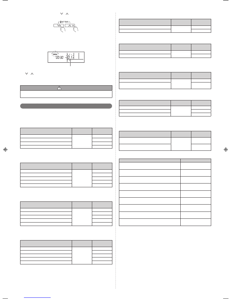
Press the set temperature buttons (
(3)
) (
) to select the setting value.
The display flashes as shown to the right during setting value selection.
Press the TIMER SET button to confirm the setting. Press the TIMER SET button for a
(4)
few seconds until the setting value stops flashing.
If the setting value display changes or if “- -” is displayed when the flashing stops,
the setting value has not been set correctly. (An invalid setting value may have been
selected for the indoor unit.)
SU MO TU WE TH FR SA
Setting value
Repeat steps 2 to 5 to perform additional settings. Press the set temperature buttons
(5)
(
) (
) and fan control button simultaneously again for more than 5 seconds
to cancel the function setting mode. In addition, the function setting mode will be
automatically canceled after 1 minute if no operation is performed.
After completing the FUNCTION SETTING, be sure to turn off the power and turn it on again.
(
6
)
CAUTION
After turning off the power, wait 30 seconds or more before turning on it again. The
FUNCTION SETTING doesn’t become effective if it doesn’t do so.
Function setting
8
1 21
Filter Sign
The indoor unit has a sign to inform the user that it is time to clean the filter. Select the
•
time setting for the filter sign display interval in the table below according to the amount
of dust or debris in the room. If you do not wish the filter sign to be displayed, select the
setting value for “No indication”.
(The unit is factory-set to “03”.)
Setting Description
Function
Number
Setting
Value
Standard (2500 hours)
11
00
Long interval (5000 hours)
01
Short interval (1250 hours)
02
No indication
03
Setting the Static Pressure
Select appropriate static pressure according to the installation conditions.
•
(The unit is factory-set to “00”.)
Refer to the technical manual for details or follow the instructions of the duct designer.
•
Setting Description
Function
Number
Setting
Value
Normal (60Pa)
21
00
static pressure 1 (100Pa)
02
static pressure 2 (150Pa)
03
static pressure 3 (200Pa)
04
static pressure 4 (250Pa)
05
Setting the Cooler Room Temperature Correction
Depending on the installed environment, the room temperature sensor may require a
•
correction. The settings may be selected as shown in the table below.
(The unit is factory-set to “00”.)
Setting Description
Function
Number
Setting
Value
Standard (No correction)
30
00
Low control (-1.0°C)
01
Slightly lower control (-0.5°C)
02
Slightly warmer control (+0.5°C)
03
Warmer control (+1.0°C)
04
Setting the Heater Room Temperature Correction
Depending on the installed environment, the room temperature sensor may require a
•
correction. The settings may be selected as shown in the table below.
(The unit is factory-set to “00”.)
Setting Description
Function
Number
Setting
Value
Standard (No correction)
31
00
Low control (-1.0°C)
01
Slightly lower control (-0.5°C)
02
Slightly warmer control (+0.5°C)
03
Warmer control (+1.0°C)
04
Auto Restart
(The setting value is factory-set to “00”.)
Setting Description
Function
Number
Setting
Value
Yes
40
00
No
01
Indoor Room Temperature Sensor Switching Function
(Wired remote controller only)
(The setting value is factory-set to “00”.)
Setting Description
Function
Number
Setting
Value
Only the sensor of the indoor unit is used
42
00
The sensor of the wired remote controller is used
01
Cool Air Prevention
This setting is used to set the fan speed when the compressor stops once the room
•
temperature has reached the set temperature during heating operation.
(The unit is factory-set to “00”.)
Setting Description
Function
Number
Setting
Value
Super low
43
00
Follow the setting on the remote controller
(corresponding to ventilation)
01
External input control
“Operation/Stop” mode or “Forced stop” mode can be selected.
•
(The unit is factory-set to “00”.)
Setting Description
Function
Number
Setting
Value
Operation/Stop mode
46
00
(Setting forbidden)
01
Forced stop mode
02
Room Temperature Control Switching
This setting is used to set the room temperature control method when the wired remote
•
controller is selected by the Indoor Room Temperature Sensor Switching Function.
(The unit is factory-set to “00”.)
Setting Description
Function
Number
Setting
Value
Control by the sensors of both the indoor unit
and the wired remote controller.
48
00
Control only by the sensor of the wired remote
controller.
01
Setting record
Record any changes to the settings in the following table.
Jumper wire
Setting Value
Filter Sign
Static Pressure
Cooler Room Temperature Correction
Heater Room Temperature Correction
Auto Restart
Room Temperature Sensor Switching
Cool Air Prevention
External input control
Room Temperature Control Switching
After completing the FUNCTION SETTING, be sure to turn off the power and turn it on
•
again.
9380441038_IM.indb 9
28/1/2556 13:44:42
En-10
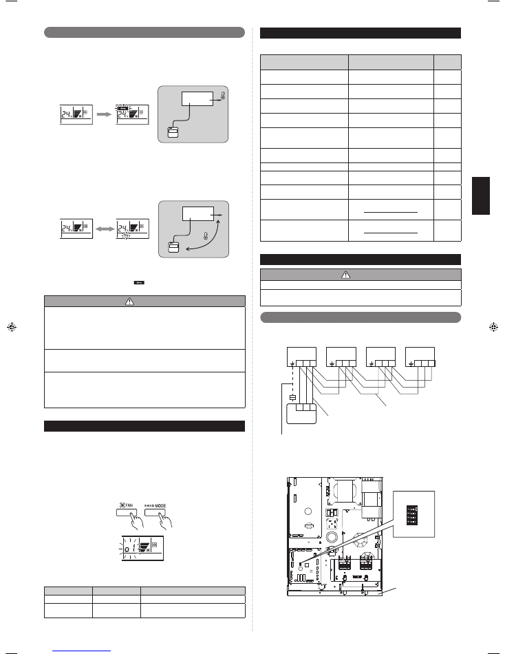
Setting the room temperature detection location
8
1
4
1
The detection location of the room temperature can be selected from the following two
•
examples. Choose the detection location that is best for the installation location.
A. Indoor unit setting (factory setting)
The room temperature is detected by the indoor unit temperature sensor.
•
When the THERMO SENSOR button is pressed, the lock display flashes because the
(1)
function is locked at the factory.
A
Indoor unit
B. Indoor unit/remote controller setting (room temperature sensor selection)
The temperature sensor of the indoor unit or the remote controller can be used to detect
the room temperature.
Enable the room temperature sensor selection in FUNCTION SETTING, which will be
(1)
described later.
Press the THERMO SENSOR button for 5 seconds or more to select the temperature
(
2
)
sensor of the indoor unit or the remote controller.
B
Indoor unit
NOTE
If the function to change the temperature sensor is used as shown in examples A (other
than example B), be sure to lock the detection location.
If the function is locked, the lock display
will flash when the THERMO SENSOR
button is pressed.
CAUTION
If the difference between the room temperature and wall temperature is great as the
external and internal walls are joined and the wall temperature is easily affected by the
outside air, the detected temperature may be different from the actual room temperature
because the sensor of the remote controller detects the temperature near the wall surface.
Especially when the remote controller is installed on a wall that is directly exposed to the
outside air, it is recommended to use the indoor unit temperature sensor.
Do not use the temperature sensor of the remote controller as a substitute for the
indoor unit temperature sensor which has problem in the temperature detection. (Solve
the problem of the indoor unit temperature sensor.)
If the unit is installed in a room with a ceiling of 3 m or higher, the temperature may not
be detected properly with the indoor unit temperature sensor as there may be a large
difference between the temperature near the ceiling and the floor.
In this case, it is recommended to take a measure such as installation of an optional
remote sensor and room air ventilation using a circulator.
TEST RUN
9
1
CHECK ITEMS
Is operation of each button on the remote control unit normal?
(1)
Is the drain normal?
(
2
)
Is there any abnormal noise and vibration during operation?
(3)
Do not operate the air conditioner in the running state for a long time.
(4)
[Operation method]
For the operation method, refer to the Operating Manual.
•
Stop the air conditioner operation.
(1)
Press the MODE button and the FAN button simultaneously for 2 seconds or more to
(
2
)
start the test run.
Test run display
Press the START/STOP button to stop the test run.
(3)
If “C0” appears in the R.C. address display, there is a remote controller error.
R.C. address
Error code
Content
C0
15
Incompatible indoor unit is connected
C0
12
Indoor unit ↔ remote controller
communication error
CHECK LIST
10
1
Pay special attention to the check items below when installing the indoor unit(s). After
installation is complete, be sure to check the following check items again.
Check items
If not performed correctly
Check
box
Has the indoor unit been installed
correctly?
Vibration, noise,
indoor unit may drop
Has there been a check for gas leaks
(refrigerant pipes)?
No cooling, No heating
Has heat insulation work been
completed?
Water leakage
Does water drain easily from the
indoor units?
Water leakage
Is the voltage of the power source the
same as that indicated on the label on
the indoor unit?
No operation, heat or burn damage
Are the wires and pipes all connected
completely?
No operation, heat or burn damage
Is the indoor unit grounded?
Short circuit
Is the connection cable the specified
thickness?
No operation, heat or burn damage
Are the inlets and outlets free of any
obstacles?
No cooling, No heating
After installation is completed, has the
proper operation and handling been
explained to the user?
Operate the unit according to the
operating manual provided, and check
that it is operating normally.
SPECIAL INSTALLATION METHODS
11
1
CAUTION
Be sure to turn off the electrical breaker before making settings.
When setting DIP switches, do not touch any other parts on the circuit board directly
with your bare hands.
Group control system
11
1
1
1
A number of indoor units can be operated at the same time using a single remote controller.
(1) Wiring method (indoor unit to remote controller)
1 2 3
1 2 3
1 2 3
1 2 3
1 2 3
Indoor unit 0
Indoor unit 1
Indoor unit 2
Indoor unit 3
Bus wire
Remote
controller cable
Remote controller
R W B
When earth (ground) wire is necessary
(2)
Set the R.C. address (DIP switch setting)
Set the R.C. address of each indoor unit using the DIP switch on the indoor unit
circuit board.
The DIP switch is normally set to 0.
SW 50
ON
OFF
Control box
DIP switch
9380441038_IM.indb 10
28/1/2556 13:44:43
En-11
Set the R.C. address in accordance with the table below.
R.C. address
DIP switch
1
2
3
4
0
OFF
OFF
OFF
OFF
1
ON
OFF
OFF
OFF
2
OFF
ON
OFF
OFF
3
ON
ON
OFF
OFF
4
OFF
OFF
ON
OFF
5
ON
OFF
ON
OFF
6
OFF
ON
ON
OFF
7
ON
ON
ON
OFF
8
OFF
OFF
OFF
ON
9
ON
OFF
OFF
ON
10
OFF
ON
OFF
ON
11
ON
ON
OFF
ON
12
OFF
OFF
ON
ON
13
ON
OFF
ON
ON
14
OFF
ON
ON
ON
15
ON
ON
ON
ON
NOTE
Be sure to set consecutive R.C. address.
The indoor units cannot be operated if a number is skipped.
Settings when simultaneous multi included.
(3) Set the refrigerant circuit address (Remote controller setting)
Turn on all of the indoor units.
1.
Turn on the indoor unit with the R.C. address 00 last. (Within 1 minute)
Set the refrigerant circuit address. (Assign the same number to all of the indoor
2.
units connected to an outdoor unit.)
Refrigerant circuit
address
Function Number
Setting Value
02
00~15
(4) Set the “Primary” and “Secondary” settings. (Set the indoor unit that is connected to
the outdoor unit using a transmission cable as the “Primary”.)
Function Number
Setting Value
Primary
51
00
Secondary
01
After completing the function settings, turn off all of the indoor units, and then turn
them back on.
If error code 21, 22, 24 or 27 is displayed, there may be an incorrect setting. Perform
*
the remote controller setting again.
NOTE
When different indoor unit models are connected using the group control system, some
functions may no longer be available.
If the group control system contains multiple units that are operated simultaneously, con-
nect and set the units as shown below.
• Auto-changeover operates under the same mode with model R.C. address 00.
• It should not be connected to any other Gr that is not of the same series (A**G only).
Simultaneous
twin
Standard
pair
Remote
controller
Indoor
unit
Outdoor
unit
1
Outdoor
unit
2
Outdoor
unit
3
Indoor
unit
Indoor
unit
Indoor
unit
Indoor
unit
Indoor
unit
R.C.address
(DIP switch setting)
: Transmission cable, Power supply cable
: Remote controller cable
: Bus wire
: Power supply cable
•
Primary/Secondary
(Function number 51)
•
Refrigerant circuit address
(Function number 02)
Simultaneous
triple
Make sure that the indoor unit with the R.C. address 0 is connected to the outdoor
*
unit using a transmission cable.
Fan delay setting
11
1 21
This setting can be used when the auxiliary heater is mounted.
When the operation is stopped when the indoor unit is operating with an auxiliary heater,
the operation continues 1 minutes.
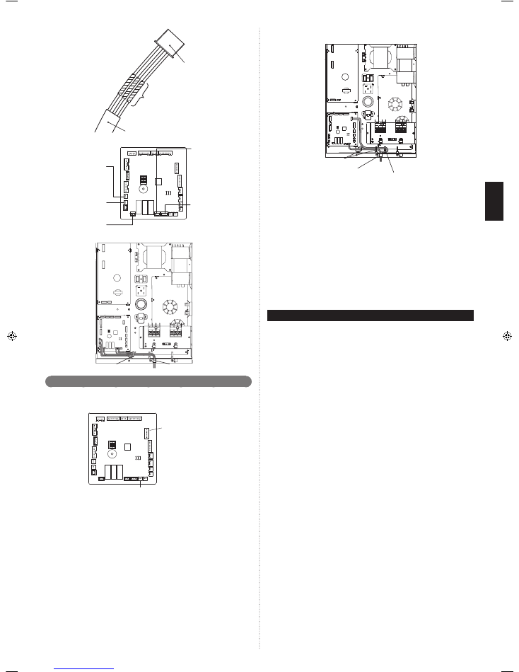
(1) Jumper wire setting (indoor unit)
This setting is made by cutting the jumper wires on the circuit board of the indoor
unit.
JM42
JM41
JM40
Control box
Jumper wires
Jumper wire
JM state
JM 42
Connect
Invalidity (Factory setting)
Disconnect
Validity
Dual remote controllers
11
1 21
Two separate remote controllers can be used to operate the indoor units.
•
The timer and self-diagnosis functions cannot be used on the slave units.
•
(1) Wiring method (indoor unit to remote controller)
1 2 3
1 2 3
1 2 3
Indoor unit
Remote controller cable
Remote controller
When earth (ground)
wire is necessary
Primary unit
R W B
R W B
Secondary unit
(2)
Remote controller DIP switch 1 setting
Set the remote controller DIP switch 1 No. 2 according to the following table.
(Refer to 7.2. Setting the dip switches)
DIP SW 1-No. 2
Primary unit
OFF
Secondary unit
ON
OPTIONAL PARTS
1
21
WARNING
Regulation of cable differs from each locality, refer in accordance with local rules.
External input and external output
1
21
1
1
Connection methods
• Wire modification
Use a tool to cut off the terminal on the end of the wire, and then remove the insulation
from the cut end of the wire.
Connect the wire with connecting wire with solder.
Important: Be sure to insulate the connection between the wires.
9380441038_IM.indb 11
28/1/2556 13:44:45
En-12
Option parts
External input/output wire
Insulated connection
Field supply
• Connection terminals
CN100
Operation status
output (White)
CN103
Control input
(Operation/stop)
(White)
CN101
Error status
output (Black)
CN160
External electrical
heater control
output (Orange)
CN161
Fresh air control
output (Green)
CLIP
Cable tie (Medium)
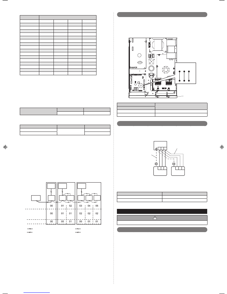
I.R. receiver unit / Remote sensor
1
21 21
Connection method
• Connection terminals
I.R. receiver unit
(CN130)
Remote sensor (CN113)
• Wiring arrangement
CLIP
Cable tie (Medium)
Connector
I.R. receiver unit
• Use 7 pins for I.R. receiver unit cable
Remote sensor
Remove the existing connector and replace it with the remote sensor connector (ensure
•
that the correct connector is used).
The original connector should be insulated to ensure that i
•
t does not come into contact
with other electrical circuitry.
Setting for room temperature control setting
When a remote sensor is connected, set the function setting of indoor unit as indicated
below.
Set Function Number “48” (Room temperature setting) to “01”
•
Setting for room temperature correction
When a remote sensor is connected, set the function setting of indoor unit as indicated
below.
Set Function Number “30” (Cooler air temperature correction) to “01”
•
Set Function Number “31” (Heater air temperature correction) to “01”
•
CUSTOMER GUIDANCE
1
21
Explain the following to the customer in accordance with the operating manual:
Starting and stopping method, operation switching, temperature adjustment, timer, air
(1)
flow switching, and other remote controller operations.
Air filter removal and cleaning, and how to use the air louvers.
(
2
)
Give the operating and Installation Manuals to the customer.
(3)
If the signal code is changed, explain to the customer how it changed (the system
(4)
returns to signal code A when the batteries in the remote controller are replaced).
*(4) is applicable to using wireless remote control.
9380441038_IM.indb 12
28/1/2556 13:44:46
En-13
ERROR CODES
14
1
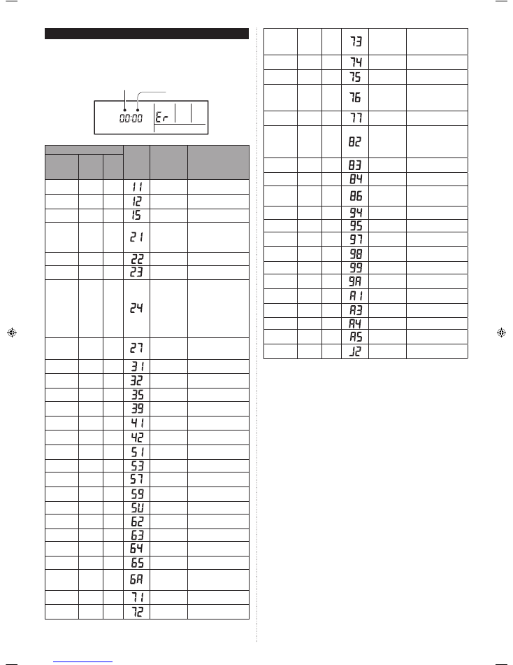
[Troubleshooting at the remote control LCD]
This is possible only on the wired remote control.
[Self-diagnosis]
For the operation method, refer to the operating manual.
•
When the error indication “E:EE” is displayed, follow the following items to perform the
•
self-diagnosis. “E:EE” indicates an error has occurred.
SU MO TU WE TH FR SA
R.C. address of INDOOR UNIT
Error code
Ex. Self-diagnosis
Error display
Wired
remote
controller
Error
code
Mode
DESCRIPTION
OPERATION
lamp
(green)
TIMER
lamp
(orange)
ECO
lamp
(green)
●
(1)
●
(1)
◊
Communication Serial communication
error
●
(1)
●
(2)
◊
Communication Wired remote controller
communication error
●
(1)
●
(5)
◊
Check run unfinished
●
(2)
●
(1)
◊
R.C. address or
Refrigerant circuit
address setting error
[Simultaneous Multi]
●
(2)
●
(2)
◊
System
Indoor unit capacity error
●
(2)
●
(3)
◊
Combination error
●
(2)
●
(4)
◊
Connection R.C.
•
address error (indoor
secondary unit)
[Simultaneous Multi]
Connection R.C.
•
address error (indoor
unit or branch unit)
[Flexible Multi]
●
(2)
●
(7)
◊
Primary unit, secondary
unit set-up error
[Simultaneous Multi]
●
(3)
●
(1)
◊
Indoor unit
Power supply interruption
error
●
(3)
●
(2)
◊
Indoor unit PCB model
information error
●
(3)
●
(5)
◊
Indoor unit
Manual auto switch error
●
(3)
●
(9)
◊
Indoor unit
fan motor driving circuit
error.
●
(4)
●
(1)
◊
Indoor unit
Inlet air temp. sensor
error
●
(4)
●
(2)
◊
Indoor unit
Indoor Heat Ex. Middle
Temp. Sensor error
●
(5)
●
(1)
◊
Indoor unit
Indoor unit fan motor1
error
●
(5)
●
(3)
◊
Indoor unit
Drainage error
●
(5)
●
(7)
◊
Damper error
●
(5)
●
(9)
◊
Indoor unit
Indoor unit fan motor2
error
●
(5)
●
(15)
◊
Indoor unit
Indoor unit error
●
(6)
●
(2)
◊
Outdoor unit Outdoor unit model
information error
●
(6)
●
(3)
◊
Outdoor unit Inverter error
●
(6)
●
(4)
◊
Active filter error, PFC
circuit error
●
(6)
●
(5)
◊
Outdoor unit I.P.M. error
●
(6)
●
(10)
◊
Display PCB
microcomputers
communication error
●
(7)
●
(1)
◊
Outdoor unit Discharge temp. sensor
error
●
(7)
●
(2)
◊
Outdoor unit Compressor temp. sensor
error
●
(7)
●
(3)
◊
Outdoor unit
Heat Ex. centre temp.
•
sensor error
Heat Ex. Liquid outlet
•
temp. sensor error
●
(7)
●
(4)
◊
Outdoor unit Outdoor temp. sensor
error
●
(7)
●
(5)
◊
Suction Gas temp. sensor
error
●
(7)
●
(6)
◊
2-way valve temp. sen
-
•
sor error
3-way valve temp. sen-
•
sor error
●
(7)
●
(7)
◊
Outdoor unit Heat sink temp. sensor
error
●
(8)
●
(2)
◊
Sub-cool Heat Ex. gas
•
inlet temp. sensor error
Sub-cool Heat Ex. gas
•
outlet temp. sensor
error
●
(8)
●
(3)
◊
Liquid pipe temp. sensor
error
●
(8)
●
(4)
◊
Outdoor unit Current sensor error
●
(8)
●
(6)
◊
Outdoor unit
Pressure sensor error
•
High pressure switch
•
error
●
(9)
●
(4)
◊
Outdoor unit Over current error
●
(9)
●
(5)
◊
Outdoor unit Compressor control error
●
(9)
●
(7)
◊
Outdoor unit Outdoor unit fan motor1
error
●
(9)
●
(8)
◊
Outdoor unit
Outdoor unit fan motor2
error
●
(9)
●
(9)
◊
Outdoor unit 4-way valve error
●
(9)
●
(10)
◊
Coil (expansion valve)
error
●
(10)
●
(1)
◊
Refrigerant
system
Discharge temp. error
●
(10)
●
(3)
◊
Refrigerant
system
Compressor temp. error
●
(10)
●
(4)
◊
High pressure error
●
(10)
●
(5)
◊
Refrigerant
system
Low pressure error
●
(13)
●
(2)
◊
Branch boxes error
[Flexible Multi]
Display mode
●
: 0.5s ON / 0.5s OFF
◊
: 0.1s ON / 0.1s OFF
( ) : Number of flashing
9380441038_IM.indb 13
28/1/2556 13:44:50