Full Text Searchable PDF User Manual
SPLIT TYPE ROOM AIR
CONDITIONER
WALL MOUNTED
type
Models
Indoor unit
Outdoor unit
ASY9FSBCW AOY9FSBC
ASY12FSBCW AOY12FSBC
CONTENTS
SPECIFICATIONS
. . . . . . . . . . . . . . . . . . . . . . . . . . 1
OUTLINE AND DIMENSIONS
. . . . . . . . . . . . . . . 3
CIRCUIT DIAGRAM
. . . . . . . . . . . . . . . . . . . . . . . . 5
REFRIGERANT SYSTEM DIAGRAM
. . . . . . . . 4
STANDARD ACCESSORIES
. . . . . . . . . . . . . . . .15
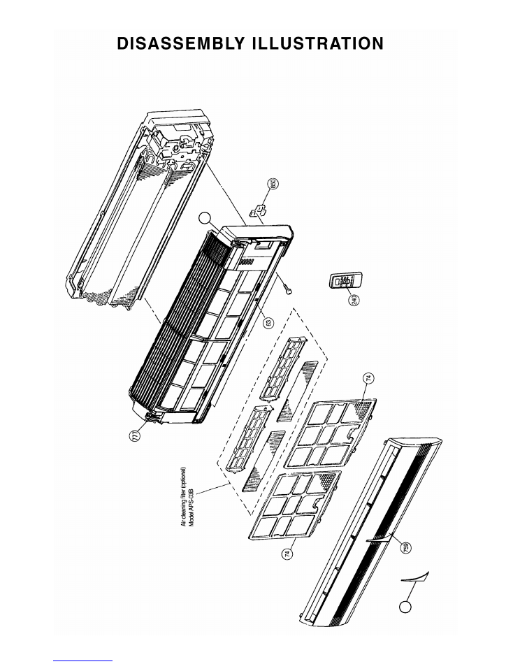
DISASSEMBLY ILLUSTRATION
. . . . . . . . . . . . .
6
PARTS LIST
. . . . . . . . . . . . . . . . . . . . . . . . . . . . . . .13
INDOOR PRINTED CIRCUIT BOARD CIRCUIT DIAGRAM
ERROR DISPLAY
. . . . . . . .
. . . . . . . .
. . . . . . . .
. . . . . . . .
. . . . . . . .
. . . . . . . .
. . . . . . . .
. . . . . . . .
. . . . . . . .
. . . . . . . .
. . . . . .
. . . . . .
. . . . . .
. . . . . .
. . . . . .
. . . . . .
. . . . . .
. . . . . .
. . . . . . . . . . . . . . . .
. . . . . . . .
. . . . . .
. . . . . . . .
. . . . .
. . .
. . .
7
9

COOLING
COOLING
ASY9FSBCW
ASY12FSBCW
AOY9FSBC
AOY12FSBC
(kW)
2.75
3.40
ELECTRICAL DATA
230V 50Hz
230V 50Hz
4.7
6.2
1.05
1.33
2.62
2.56
1.3
1.8
(m /hr)
540
540
COMPRESSOR
220, 230, 240V / 50Hz
220-240V / 50Hz
80230135
80235035
(g)
590
720
FAN MOTOR
POWER SUPPLY
(V)
230
230
Hi‑SPEED
(r.p.m)
1,310
1,310
MED‑SPEED
(r.p.m)
1,190
1,230
LO‑SPEED
(r.p.m)
1,070
1,150
S‑LO
(r.p.m)
960
1,080
OUTDOOR UNIT
(r.p.m)
740
740
DIMENSIONS
257 x 808 x 187
257 x 808 x 187
535 x 695 x 250
535 x 695 x 250
WEIGHT
10 / 8
10 / 8
33 / 30
35 / 32
NOISE LEVEL
Hi-SPEED
(dB)
COOL 39
COOL 39
MED-SPEED
(dB)
COOL 37
COOL 37
LO-SPEED
(dB)
COOL 34
COOL 35
S-LO
(dB)
COOL 31
COOL 33
OUTDOOR UNIT
(dB)
COOL 45
COOL 46
SPECIFICATIONS
TYPE
INDOOR UNIT
TYPE
OUTDOOR UNIT
COOLING CAPACITY
RUNNING CURRENT (A)
INDOOR
UNIT
POWER SOURCE
AIR CIRCULATION-Hi
Hermetic type, Permanent split condenser,
2 pole, Single phase, Induction motor
POWER SOURCE
DISCRIMINATION
REFRIGERANT R410A
INDOOR
UNIT
INPUT WATTS (kW)
E.E.R (kW/kW)
MOISTURE REMOVAL
GROSS
NET(kg)
INDOOR UNIT
OUTDOOR UNIT
INDOOR UNIT
OUTDOOR UNIT
H x W x D
(mm)
1
2004.04.06
3
ADDITIONAL CHARGE OF REFRIGERANT
(ASY9FSBCW / AOY9FSBC)
(ASY12FSBCW / AOY12FSBC)
Refrigerant suitable for a piping length of 7.5 m is charged in the outdoor unit at the factory.
When the piping is longer than 7.5 m, additional charging is necessary.
For the additional amount, see the table below.
PIPE LENGTH
7.5 m
10 m
ADDITIONAL REFRIGERANT
None
50 g
15 m
150 g
Between 7.5 m and 10 m, when using a connection pipe other than that in the table,
charge additional refrigerant with 20g /1 m as the criteria.
(The maximum length of piping is 15m. If the units are further apart than this, correct
operation can not be guaranteed.)
2003.10.30
- 2 -

695
250
500
Drain pipe hold 20
440
290
26
5
54
53
5
13
98
INDOOR UNIT
U nit : m m
OUTDOOR UNIT
D I M E N S I O N S
O
808
25
7
187
- 3 -
2003.10.30

3-Way valve
(with charging port)
Condenser
Dryer
Capillary tube
2-Way valve
(Flare connection)
Gas pipe (9.52 dia.)
(Flare connection)
(Flare connection)
Liquid pipe (6.35 dia.)
(Flare connection)
[ INDOOR UNIT ]
[ OUTDOOR UNIT ]
[ Connecting pipe ]
Evaporator
Com-
pressor
REFRIGERANT SYSTEM DIAGRAM
Models : ASY9FSBCW / AOY9FSBC
3-Way valve
(with charging port)
Condenser
Dryer
Capillary tube
2-Way valve
(Flare connection)
Gas pipe (9.52 dia.)
(Flare connection)
(Flare connection)
Liquid pipe (6.35 dia.)
(Flare connection)
[ INDOOR UNIT ]
[ OUTDOOR UNIT ]
[ Connecting pipe ]
Evaporator
Com-
pressor
Models : ASY12FSBCW / AOY12FSBC
2003.10.30
4
BLACK
BLACK
WHITE
BLACK
WHITE
RED
ORANGE
WHITE
RED
INDOOR UNIT
OUTDOOR UNIT
CM
FM
TERMINAL
COMPRESSOR
FAN MOTOR
FAN MOTOR
CAPACITOR
OVERLOAD
RELAY
COMPRESSOR
CAPACITOR
N
L
R
C
S
Models : ASY9FSB CW / A OY9FSB C
ASY12FSB CW / A OY12FSB C
CIRCUIT DIAGRAM
5
2003.10.30
CONTROL BORAD
STEP
MOTOR
M
FM
FAN MOTOR
BLACK
YELLOW
WHITE
1 2 3 4 5
5
4
3
2
1
1
2
3
4
5
6
7
8
8
8
7 7
6 6
5 5
4
4
3 3
2 2
1 1
3
4
6
6
7
7
8
8
9
9
10
10
1
1
2
2
1
2
3
4
5
1
1
1
1
2
2
3
3
2
2
3
3 4
4
5
5
6
6
6
5
4
3
2
1
1
1
2
2
3
3
2
2
2
2
1
1
1
1
POWER SUPPLY BOARD
TRANSFORMER
TERMINAL
BLACK
P
U
R
P
LE
P
U
R
P
LE
R
E
D
R
E
D
G
R
E
E
N
G
R
A
Y
G
R
A
Y
W
H
IT
E
B
R
O
W
N
B
LU
E
GREEN / YELLOW
W
H
IT
E
W
H
IT
E
W
H
IT
E
W
H
IT
E
W
H
IT
E
W
H
IT
E
B
LA
C
K
R
E
D
R
E
D
G
R
A
Y
G
R
A
Y
B
LA
C
K
B
LA
C
K
B
LU
E
P
IN
K
Y
E
LL
O
W
O
R
A
N
G
E
R
E
D
WHITE
WHITE
WHITE
WHITE
WHITE
WHITE
WHITE
BLUE
R
E
LA
Y
K103
DISPLAY
T
E
S
T
CN5
CN3
CN2
CN4
CN8
C
N
6
C
N
1
T
H
E
R
M
IS
T
O
R
(R
O
O
M
T
E
M
P
. )
T
H
E
R
M
IS
T
O
R
(P
IP
E
T
E
M
P
. )
C
N
20
1
C
N
10
5
CN101
W
10
1
W
10
3 CN103 CN104
CN102
THERMAL
FUSE
T
H
E
R
M
A
L F
U
S
E
L
L
N
N
LOUVER
OPERATE
TIMER
SWING
C104
0.1
12V
12V
5V
SSR101
G3MC-201PL-VD DC12V
12V
L101
SS11V-10062
D101
S1VB20
D103
1SR139
+
C108
0.1
<F>
C106
2200
/25V
Q101
2SD880
D104
MTZJ15B
+
R102
1.0K
<1/2W>
+ C109
10/
50V
R101
10K
<1/4W>
C105
2200
/35V
C101
4700P
C102
4700P
W101
E
GREEN
UL1015
AWG22
C110
VA102
470V
FAN CAPACITOR
7.0 uF
CN101 B3P5-VH-B
CN101-1
CN101-3
CN101-5
BLACK
YELLOW
WHITE
RED
CN7-3
CN7-1
CN7-2
WHITE
BLACK
FAN MOTOR
S3P-VH CN8
5V
5V
C1
0.1
<F>
R1
10K <1/10W>
R14
10K <1/10W>
12V
BZ1
PKM13EPY-4000
B Z
Q2
DTC124EUA
5V
R2 1.0K
<1/10W>
C2
0.1
<F>
12V
IC101
7805
I
O
G
D102
1SR139
12V
K103
G4A-1A-E-PS
CN105
PHR-8
CN6
B8B-PH-K-S
5V
C11
0.1
<F>
EEPROM
IC2
BR93LC46
VCC
D0
TEST
GND
CS
SK
D1
NC
8
4
6
5
7
3
2
1
10
12
11
5V
5V
R12 10K
<1/10W>
IC4-7 uLN2003
IC4-5 uLN2003
IC4-6 uLN2003
R33 10K
<1/10W>
7
5
6
1
2
3
C9 0.01
<R>
R7 4.7K
<1/8W>
C8
0.1
<F>
R6 1.0K
<1/8W>
Q3 DTC124EUA
5V
R8 10K
<1/10W>
Q1 DTC124EUA
1
2
3
C7
10/
25V
+
JP1
JP3
JP4
JP2
R3, R34, R5, R35
10K <1/10W>
3
2
1
5V
5V
R29 10K
<1/10W>
R28 10K
<1/10W>
R30 1.0K
<1/10W>
SW1
MANUAL AUTO
SWITCH
5V
C27
0.1
<F>
IC3
BD4742G
RESET
R27
10K (1%)
<1/10W>
R26
49.9K (1%)
<1/10W>
3
4
5
2
1
R24 390
<1/10W>
R25 390
<1/10W>
C21
0.1
<F>
C25
0.1
<F>
C22
0.1
<F>
5V
R20 - R23
10K <1/10W> x 4
5V
C16
1000P
<R>
R19 10K
<1/10W>
R18 47
<1/10W>
5V
12V
R17 330 <1/10W>
R15 330 <1/10W>
R16 330 <1/10W>
12V
X1
CST8.38MHz
IC4-1 uLN2003
IC4-4 uLN2003
IC4-3 uLN2003
IC4-2 uLN2003
8
4
13
3
14
2
15
16
1
9
2
33
32
X1
X2
45
46
47
48
49
50
51
52
5
6
7
35
11
12
38
13
19
29
25
24
28
8
44
37
14
15
16
43
27
10
20
26
23
22
30
9
34
21
4
36
1
2
3
42
41
40
39
17
18
31
P43
P42
P41
P40
P44
P45
P46
P47
P54
P55
P56
P00
P34
P35
P36
P03
P25
XT2
P10
P11
RESET
P57
P75
P02
P20
P21
P22
P74
AVDD
VDD0
VDD1
AVREF
P12
P13
XT1
VSS0
VSS1
AVSS
P53
P01
P50
P51
P52
P73
P72
P71
P70
P23
P24
I C
CN2-1
BLACK
CN2-2
BLACK
CN3-2
GRAY
CN3-1
GRAY
CN1-1
CN4-1
RED
CN1-5
CN1-4
CN1-3
CN1-2
CN4-2
WHITE
CN4-3
WHITE
CN4-4
WHITE
CN4-6
WHITE
CN4-5
WHITE
CN5-6
RED
CN5-7
ORANGE
CN5-8
YELLOW
CN5-9
PINK
CN5-10
BLUE
UL1061 AWG26 x 5
UL1061 AWG26 x 6
1
5
4
3
2
6
5V
X201
GP1UM261RK
VCC
GND
DATA
+
R201 47
<1/4W>
C202
0.1
<F>
C201
47/10V
D201 SLR-325<VC>
RED
D202 SLR-325<MC>
GRN
D203 SLR-325<DC>
ORG
CN201
CN5 53325-0510
B6B-PH-K-S
CN4
CN1
B5P-SHF-1AA
CHECKER
INDICATOR PCB
K04AS-0400WSE-D0
CN2
150-103-86176
CN3
150-503-96077
ROOM TEMPERATURE THERMISTOR
PIPE TEMPERATURE THERMISTOR
VA101
470V
C103
0.1
FH101
F101
T 3.15A 250V
F102
W103
BLACL
BROWN
BLUE
UL1015 AWG14
UL1015 AWG22
U
L1
01
5
A
W
G
22
WHITE
U
L1
01
5
A
W
G
22
B
LA
C
K
POWER SOURCE
230V
50Hz
TERMINAL BOARD
GREEN / YELLOW
N L
POWER TRANSFORMER
EZ-030HSE-T
T
H
E
R
M
A
L
F
U
S
E
PRIMARY
SECONDARY
T
H
E
R
M
A
L
F
U
S
E
(
10
3
)
C
N
10
2-
3
P
U
R
P
LE
C
N
10
2-
1
P
U
R
P
LE
C
N
10
4-
1
R
E
D
C
N
10
4-
2
R
E
D
C
N
10
3-
2
G
R
AY
C
N
10
3-
1
G
R
AY
B
2P
3-
V
H
-B
B
2B
-X
H
-A
M
B
2B
-X
A
S
K
-1
-A
C
N
10
2
C
N
10
3
C
N
10
4
POWER SUPPLY PCB
K04AS-0400WSE-P0
F M
CN105-1
CN6-2
CN6-1
CN105-8
CN105-7
CN105-6
CN105-5
CN105-4
CN105-3
CN105-2
BLUE
WHITE
WHITE
WHITE
WHITE
WHITE
WHITE
WHITE
CN6-4
CN6-8
CN6-7
CN6-6
CN6-5
CN6-3
UL1061 AWG26 x 8
HEATING TEMPERATURE
CORRECTION 1
HEATING TEMPERATURE
CORRECTION 2
AUTO RESTART
REMOTE CONTROL
CUSTOM CODE
CONTROLLER PCB ASSEMBLY ( MAIN PCB )
ASY9FSBCW : K02DE-0405WSE-C1
ASY12FSBCW : K02DE-0406WSE-C1
I C 1
uPD780024-X02-8ET
2005.04.14
- 6 -
I N D O O R P R I N T E D C I R C U I T B O A R D
C I R C U I T D I A G R A M
Models : ASY9FSBCW
ASY12FSBCW
2003.10.30
7
Troubleshooting
check table
Operation lamp
: Red lamp
Timer lamp
: Green lamp
Error contents
Error contents
thermistor error
RED lamp
(2 times) thermistor error (room temp.)
RED lamp
Green lamp
Green lamp
(2 times)
thermistor error (heat exchanger)
RED lamp
Green lamp
(3 times)
control unit error
RED lamp
(4 times) MANUAL AUTO button error
RED lamp
(indoor unit )
Green lamp
Green lamp
(2 times)
power source Hz decision error
RED lamp
Green lamp
(4 times)
fan motor error
RED lamp
(6 times) lock error
RED lamp
(indoor unit)
Green lamp
Green lamp
(2 times)
rpm error
RED lamp
Green lamp
(3 times)
: 0.5s ON/OFF repeated
: 0.1s ON/OFF repeated
LED indication
LED indication
Small division indication
Large division indication
ERROR DISPLAY
2004.04.09
8
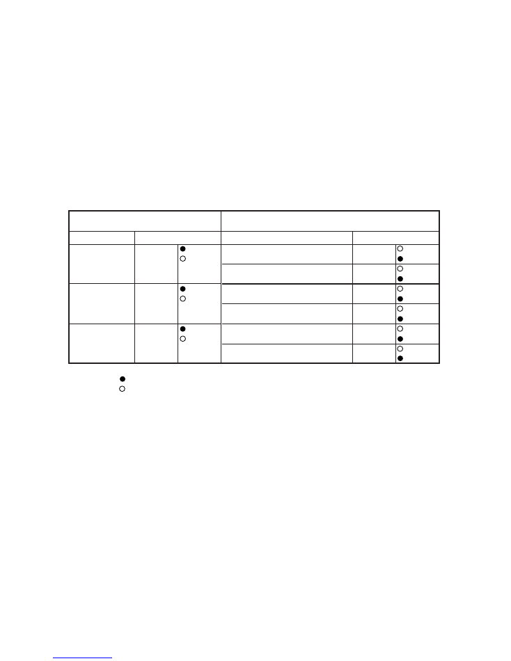
Thermistor resistance values <Indoor unit side>
ASY9FSB, ASY12FSB
1) Room temperature thermistor (TH
IA
)
Room tempera-
ture ( C)
Resistance value
(k )
0
33.6
2.5
29.5
5
25.9
7.5
22.8
10
20.2
12.5
17.9
15
15.8
17.5
14.1
20
12.5
22.5
11.2
25
10.0
27.5
9.0
30
8.0
Room tempera-
ture ( C)
Resistance value
(k )
32.5
7.2
35
6.5
37.5
5.9
40
5.3
42.5
4.8
45
4.3
47.5
3.9
50
3.6
2) Indoor heat exchanger temperature thermistor (TH
HM,
TH
HI
)
Heat exchanger
ture ( C)
Resistance value
(k )
0
176.0
2.5
153.5
5
134.2
7.5
117.6
10
103.3
12.5
91.0
15
80.3
17.5
71.0
20
62.9
22.5
55.9
25
49.7
27.5
44.3
30
39.6
Resistance value
(k )
32.5
35.4
35
31.7
37.5
28.5
40
25.6
42.5
23.1
45
20.8
47.5
18.8
50
17.1
52.5
55
57.5
60
15.5
14.1
12.8
11.6
tempera
Heat exchanger
ture ( C)
tempera
9
2004.02.18
Model : ASY9FSBCW
ASY12FSBCW
77
7
77
7
10
2003.04.23

98
5
98
6
2003.04.23
11
12
2003.04.23
98
5
98
6
When you order parts, please make a photocopy of this page
and fill the number of the parts in the "Order" column.
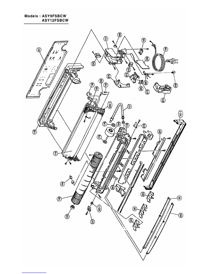
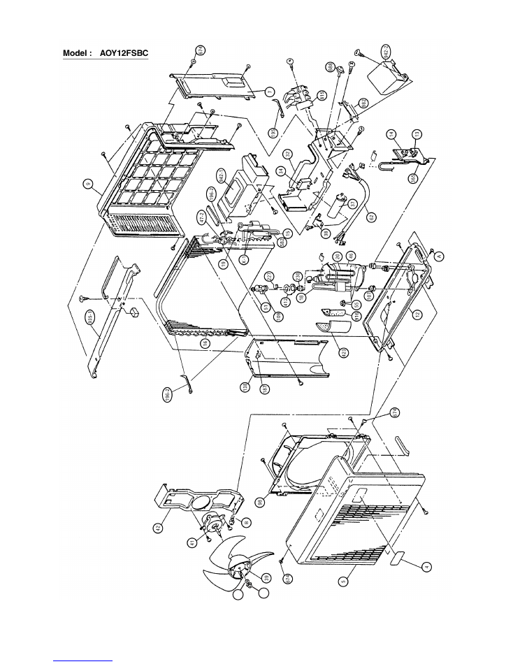
INDOOR UNIT
PARTS LIST
Ref.
No.
Description
Ord.
Q`ty
63
9312417032
9312417063
65
Flow Control Panel-Z
9306058043
9306058043
69
9306055028
9306055028
74
Louver-A
Filter
9305444014
9305444014
108
9309755062
9309755062
109
9306052027
9306052027
122
9303066010
9303066010
127
Drain Hose Assy
9305550029
9305550029
146
9330144019
9330144019
151
9330007017
9330007017
158
Connecting Pipe Assy
9306416010
9306416010
164
Fan Motor Assy-IN
9601172017
9601172017
169
Cross-Flow Fan Assy
9307836015
9307836015
178
9601302018
9601302018
184
313728262708
313728262708
185
9330015012
9330015012
188
Power Cord Assy
9702595043
9702595043
196
313035356905
313035356905
233
9701803026
9701803026
235
Base
Casing
S haft Holder-B
Evaporator Assy
Control Box
Motor Cushion-M
Thermistor S pring
Wire Clamp
Clamp S KB-150
Power Transformer
Thermistor Assy-Pipe
9702039059
9702039059
236
Controller PCB Assy
9706046060
9706046077
240
R emote Control Unit
9312058037
9312058037
Part No.
401
Wall Hook Bracket
9304358008
9304358008
440
Flow Control Panel-U
9306057046
9306057046
466
313714328805
313714328805
522-1
9306062002
9306062002
523
Gear Bracket
9306407001
9306407001
652-1
Thermistor Holder Pipe
313714262805
313714262805
668
313681304205
313681304205
687
9330012011
9330012011
759
9330001015
9330001015
764
Drain Cap Assy
9304150008
9304150008
777
9306755010
9306755010
815
9900040062
9900040062
850
9330003019
9330003019
872
9330009011
9330009011
873
9330014015
9330014015
874
Control Box Cover
9330008014
9330008014
875
Power S upply PCB Assy
9706051019
9706051019
876
9900139018
9900139018
ASY9FSBCW
ASY12FSBCW
283
9303529010
9303529010
323
9306056025
9306056025
385
Indicator PCB Assy
9706053013
9706053013
13
767-1
Clamp NK-4N
Gear-A
S crew w/Washer
Earth Terminal
Intake Grille-A
Terminal
Window (R eceiver)
Indicator Case
Lamp Cover
S tep Motor
Bushing-A
Louver-B
Bottom Cover-A
9330004016
9330004016
Clamper (Grille)
2005.04.14
Panel (Front) Total Assy
877
Face Panel (Front)-A
9330005044
9330005044
W hen you order parts, please make a photocopy of this page
and fill the number of the parts in the "Order" column.
Q'ty
AOY9FSBC
AOY12FSBC
Ð 19 Ð
OUTDOOR UNIT
Ref.
No.
Description
Ord.
4
9308468017
5
Cabinet Front Panel, Plastic
9306386016
7
Emblem-R ear
Connector Cover
(Cabinet)
9306119010
9
Cabinet R ear Panel, Plastic
9306385019
12
Base Assy, Painted
9306118020
13
9310085011
14
9310084014
16
9308463036
18
9308675002
19
Capillary Tube
9308670007
BR S heet 30x120x T7
9305039036
BR S heet 170x130x T2
9305498062
9305039166
BR S heet 100x160x T5
32
Control Box Metal
9308561015
34
Capacitor (Fan Motor)
9900089023
37
9307588013
38
Clamp Metal (Capacitor)
313468061808
39
9305538003
41
Fan Motor Assy-Out
9307715013
42
9305536016
46
3-Way Valve
2-Way Valve
Condenser Assy
S uction Pipe
Capacitor (R unning)
Propeller Fan
Bracket (Motor)
Compressor Assy
9310112014
51
S pecial Nut M5
313199233602
55
S pecial Nut M6
313252257701
62
Wire Assy (S hield)-A
9305695027
9305581023
9351813017
109
9351120009
138
S eparate Wall Metal
9305971008
187
9308468017
9306386016
9306119010
9306385019
9306118020
9310085011
9310084014
15
Dryer
9312056002
9312056002
9308463036
9308679000
9308668004
20
Discharge Pipe Assy
9308677006
9308681003
9305039074
9305039029
9305039067
9308561015
9900089023
9307588013
313468061808
9305538003
9307715013
9305536030
9310110010
47-2
Discharge
Pipe R ubber
313185159802
313185159802
313199233602
313252257701
9305695027
98
Fan R ing
9305581023
107
R ubber S eat-A
9351813017
9351120009
9305971008
313361271706
195
Terminal Cover
(Comp.)
Clamp No.1219
Clamp S KB-100
313361275805
313361271706
313361275805
Part No.
230
9308430007
365
9306748012
412
Terminal Gasket (Comp.)
9351121006
423
9308464019
582
Outlet Pipe
(Cond.)
9312269006
674
9307303012
9305973002
9308562012
9356802009
0700179013
9304902003
9304903000
688
313681304205
815
9306489014
R einforcement(Cabinet
Top)
9305973002
916
9306362003
942-1
Control Box Cover-A Metal
982
Cord Clamp (Plastic, Black)
9302271002
985
S pecial Nut w/Washer
9304902003
986
9304903000
9308667007
A
S crew (serrated)
S crew (with S pring Washer)
B
9356802009
0700179013
9308445001
9306748012
9351121006
9308464019
9312270002
9307303012
313681304205
9306489014
9306362003
9308562012
942-2
Control Box Cover-B Metal
9305975006
9305975006
9302271002
935-1
Connection Pipe (Capillary)
X-1
9308667007
196-2
Overload R elay
Bracket (Valve)
Noise Insulation-B
Tapping S crew
(S pecial)
S crew (with
S quare
Washer)
Terminal-3P
Noise Insulation-G
S pecial Washer
Clamp S KB-3MC
9305335008
9305335008
------
9305498062
BR S heet 55 x 135x T2
9305039166
BR S heet 100x120x T5
9305039029
BR S heet 180x180x T2
9305039067
9305039074
2004.05.10
14
Note :
Always use specified screws, since Ref No. 668, A and B are screws for the earth.
Ref No. 668 : Machine screw (with spring washer) M4 x P0.7 x L10, plating thickness 5 or more
A : Tapping screw (with inner clip washer) M4 x L10, plating thickness 5 or more
B : Machine screw (with spring washer) M4 x P0.7 x L10, plating thickness 5 or more
Name and Shape
Part No.
ASY9FSBCW
ASY12FSBCW
0700076046
9308117007
0600185534
9312094066
9304358008
Remote control
unit
Battery (penlight)
Cloth tape
Tapping screw
(4 x 25)
Wall hook bracket
STANDARD ACCESSORIES
2003.10.30
15

0302G2112