Full Text Searchable PDF User Manual

SERVICE
Vidasýz
Montaj
KK-AS2
0E/060801-2
T:/p/kk/eds/ing/AS2
0eng
5
5
8
8
EDS Elektronik Destek
Sanayi ve Ticaret Ltd. Þti.
Meclis Mah. Teraziciler Cad.
K ý l ý ç S o k . N o : 4 3 4 7 8 5
S a r ý g a z i /
Ý s t a n b u l
www.eds.com.tr eds@eds.com.tr
+90 216 528 45 00
+90 216 314 17 80
Tel.
Fax
:
:
INSTALLATION MANUAL
AS 250
OUTDOOR SOUNDER
OUTDOOR SOUNDER
AS 250
2
8
AS 250
13.6VDC
38mA
300-450mA (Audio type is depend on)
102dB-108dB
2.0-4Khz
Selectable (5 min.)
5/15min. selectable
- and +
Single Piezo
Negative/Pozitive selectable
100.000p/Lum
1.000.000
120/min.
Red/Blue
Walking LED
Available
Outdoor
Alarm Panels
ABS Plastic
White,
210x320x80
920gr
-10 C
+50 C
4 selectable
° ~
°
(Audio type is depend on)
6V 280mAH NiCd
Galvanized
2. Piezo
- 12V/1.2ah Vicd
7
8
Figure: 9
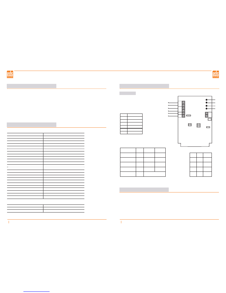
AS 250
+12V-
SAB
S
F
Buzzer
Micro
switch
JP1
Flasher Trigger
Siren Trigger
Sabotage
-
+
DC 12
Jp4
Jp3
Jp2
Jp7
Battery
AS 250 Card
Function
Voltage type
Start time set-up
Trigger type
Siren period
Siren supervise time
Jumper
JP 1
JP 2
JP 3
JP 4
JP 7
OFF
SBP is
from panel
-
Negative
5 min.
N: Negative Trigger
P: Pozitive Trigger
ON
SBA is
from battery
5 min
Pozitive
15 min.
Factory Default Values
JP 1 :
OFF
JP 2:
OFF
JP 3:
OFF
JP 4:
OFF
JP 5:
OPEN
JP 6:
OPEN
JP 7:
Negative
OUTDOOR SOUNDER
General
Techinical Specifications
AS 250 Series Outdoor Sounders are aesthetically designed, high quality sounders for outdoor usage.
These products are compatable with all security systems, durable for any kind of weather conditions and
impact.
Sounders are protected with outher plastic material (inner metal cover is optional).
AS 250 Series Sounders are compatable with all alarm panels. Interior tamper key, walking LED display is
available against the tamper and system disorders. The piezo buzzer with extremely high sound level
capacity used for As250 series sounders
AS 250 Series Sounders are designed for screwless installation
Model
Operating voltage
Stand-by current
Alarm current
Voice output
Voice frequency
Audio type
Buzzer
Trigger type
Light output
Flasher life
Flasher frequency
Colour of flasher
LED display
Tamper
Environment
Application
Housing
Colors of housing
Dimensions
Weight
Operating temperature
Programmable siren period
Start time set-up
Siren supervise resistor
Optional Accessory
Battery
Inner cover
Piezo
Connections
Warning & Cautions
Please read the manual before attempting installation or operation
minutes after the strobe stops flashing before removing the cover
WAIT 3
Do not throw into fire
Do not reverse charge
Do not short-circuit
Turn off the power immediately and contact the technician when a problem occurs.
Battery
+-
Jp
6
Jp
5
JP 5
X
X
-
-
JP 6
X
-
X
-
Audio No
Audio 1
Audio 2
Audio 3
Audio 4
X :
- :
Open
Off
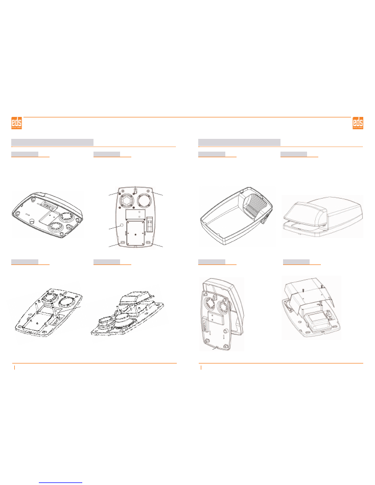
Mount
1-Turn the siren upside-down to open the cover, push the 'M' latch upwards and pull the cover below.
(Figure 1)
2-Mark the screw holes and suspender places on the wall with the aid of box bottom plastic or template on
the package for mounting. (Figure 2)
3-Set the electricity connections of the card as shown in Electricity Connections/Figure:9 and draw
attention to the sample Panel Connection section.
4-Place the battery to the slot shown in Figure 3. Be careful with the polarities and the direction of the
battery. (a battery, fix it with the cable bound and open-circuit the Jp1)
5-After completing the electricity and battery connections, place the transparent protection cover on the
card. (Figure 4)
Opening The Top Cover Before Mounting
Attaching the Top Cover
Opening The Top Cover After Mounting
3
8
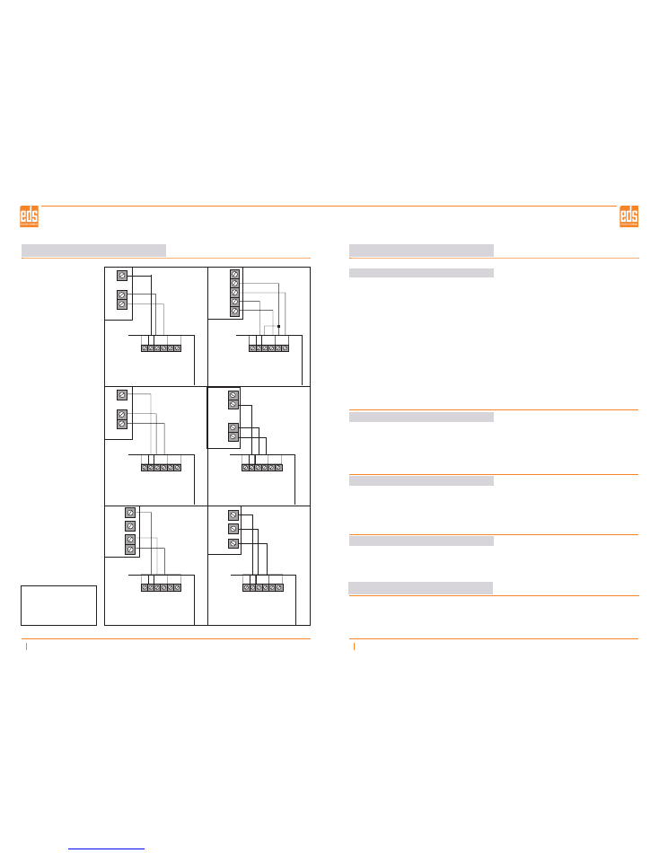
Panel Connections
6
8
GENERAL
S
S
S-
S-
S+
S+
ST8048
CLASSIC
+SİREN-
12
PREMIER 412/816
POS
COM
AUX1
CADDX NX-4/6/8
VERÝTAS 8/8R
S
D
C
A
B
Siren
trigger
Flasher
trigger
-12
V
+
- 12V + SAB
SI
FL
Flasher
Trigger
- 12V + SAB
SI
FL
Siren
Trigger
- 12V + SAB
SI
FL
- 12V + SAB
SI
FL
- 12V + SAB
SI
FL
- 12V + SAB
SI
FL
CADDX NX 4/6/8 AUX1 programmer:
(Prg. input)
(Location(Menu) NO)
(Prg. Output options)
(outrput active 0-.255min.)
(Prg. Output)
* 8 9 7 1 3 0 #
47 #
7 *
max.0 - 255dk
* 46 # 1 * * * EXIT
Flasher
Trigger
Siren
Trigger
Flasher
Trigger
Siren
Trigger
Flasher
Trigger
Siren
Trigger
Flasher
Trigger
Siren
Trigger
Flasher
Trigger
Siren
Trigger
Place the 'A' nails as they would fit into the 'B' holes as shown in Figure:7 and then make the latch be
attached to 'M' point by pressing the top cover.
Push 'M' latch in Figure:7 with a straight screw and lift the top cover. Push the cover upwards to let the
'A' nails release and remove the cover.
Mount the optionally provided metal cover as shown in Figure:8.
Mounting the Metal Cover
1- It should be at least 5cm below the ceiling in order to be able to open the top cover during assembly.
2- Choose a clean and smooth surface for easy mounting.
3- Use 4 units of M4+52 metal screw and M8 dubel(plastic screw holder in-wall)
Important Mounting Notes
OUTDOOR SOUNDER
AS 250
AS 250
OUTDOOR SOUNDER
Mount
Mount
4
8
5
8
Figure: 1
Figure: 2
Figure: 3
Figure: 4
Figure: 5
Figure: 6
Figure: 7
AKÜ
A
A
B
B
M
Figure: 8
Mounting The Metal cover
(The metal cover is optional)
Screw
Screw
Screw
Screw
Cable canal
Suspender
OUTDOOR SOUNDER
AS 250
AS 250
OUTDOOR SOUNDER