Full Text Searchable PDF User Manual
Close Control
Small Systems Range
Engineering Data Manual 50/60Hz
R407C

2
Index
Description
Page
EDPAC Company Profile
3
This Product Range
3
Other EDPAC Close Control Product Ranges
3
Equipment Nomenclature
4
Indoor Units - Dimensions and Weights
4
Air Cooled Condensers - Dimensions and Weights
5
Guide Specifications
6
General Engineering Details
11
Air Cooled Unit Schematic
12
Chilled Water Unit Schematic
13
Air Cooled Units - Cooling Capacities 50Hz
14
Air Cooled Units - Cooling Capacities 60Hz
14
Chilled Water Units - Cooling Capacities 50/60Hz
15
Electrical Details - Air Cooled Units, 400V/50Hz
16
Electrical Details - Air Cooled Units, 220V/60Hz
16
Electrical Details - Air Cooled Units, 380V/60Hz
17
Electrical Details - Air Cooled Units, 460V/60Hz
17
Electrical Details - Chilled Water Units, 400V/50Hz
18
Electrical Details - Chilled Water Units, 220V/60Hz
18
Electrical Details - Chilled Water Units, 380V/60Hz
19
Electrical Details - Chilled Water Units, 460V/60Hz
19
ENGINEERING DATA MANUAL 50/60Hz
Document Reference: E.4.19-01-03-05
While every precaution has been taken to ensure accuracy and completeness in this manual, EDPAC assumes no responsibility and disclaims
all liability for damages resulting from use of this information or for any errors or omissions.

3
HISTORY
Formed in 1968, EDPAC has grown through worldwide distribution to an installed base of over 50,000 units. EDPAC currently services
the markets of Europe, the Americas, the Middle East, and the Far East. As one of the pioneers of Precision Air Conditioning the
EDPAC name has become synonymous with quality and reliability. With its highly skilled and experienced team EDPAC has
established not only a modern manufacturing plant, but also a sophisticated and innovative product development programme. Since
1987 EDPAC International located in Cork Ireland, has controlled the entire activities of the group.
PRODUCT RANGE
EDPAC manufactures a broad range of Precision Air Conditioning equipment for the Computer Room, Telecoms and other critical
Building Services applications. EDPAC systems are designed to provide optimum operating conditions in close control environments.
QUALITY
All suppliers of materials and components used in manufacturing are assessed and qualified by EDPAC. The EDPAC guarantee of
quality is also complimented by rigorous in-factory quality assessment and quality control testing prior to product dispatch. The overall
activity of the factory is customer focused and conforms to the strict norms of IS/ISO9001/EN29001. EDPAC was awarded and has
retained this certificate since 18th March 1992.
THIS PRODUCT RANGE
SMALL SYSTEMS
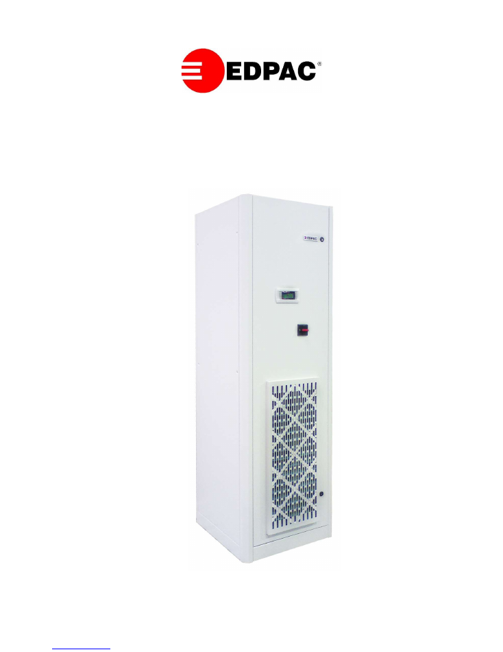
The Small Systems range comprises 2 module sizes providing nominal capacities of 6, 12 and 18 kW per module. The modules form
the basis of the EDPAC Small Systems concept. Unit selections are based on a single module. Units are available in downflow with
top return and upflow with front return. Cooling media include direct expansion using air and chilled water. The Small Systems Range
Units are equipped with: Scroll Compressors, Electrode Steam Boiler Humidifiers, Stainless Steel Tubular Finned Electric Reheat, EU4
Filtration, Belt Driven forward curved Centrifugal Fans and R407C Refrigerant. BMS interface cards are available for all of the most
commonly-used protocols including but not limited to MODBUS, BACnet, LON, JCI METASYS & they all can be integrated into
most BMS systems by RS 485 or over TCP/IP. Cooling media available is air cooled direct expansion only. There is an option for a
dual cooling version with the addition of a chilled water coil.
ASSOCIATED PRODUCT RANGES
CLOSE CONTROL MODULAR UNIT RANGE
The Close Control Modular range is comprised of 4 module sizes providing nominal capacities of 10, 15, 20, 25, 30, 35 & 40 kW per
module. These modules form the basis of the EDPAC modular concept. Unit selections can be based on a single module for a single
circuit system or any combination of 2 modules to give a twin circuit or Duplex system. The Duplex configuration is advantageous as
both modules can be positioned at different locations within the room.
CLOSE CONTROL AIR COOLED TWIN CIRCUIT UNIT RANGE
The Close Control Twin Circuit range comprises 4 sizes providing nominal capacities of 30, 40, 50, 60, 70, 80 & 100 in 10kW
increments. Units are twin circuit in a single frame and are available in upflow and downflow configurations. Cooling media available
is air cooled direct expansion only. There is an option for a dual cooling version with the addition of a chilled water coil.
EC PLUG FAN UNIT RANGE
The EC Plug Fan range comprises of 7 sizes providing nominal capacities of 20-200kW. All units are fitted with the EC plug fans and
cooling media include direct expansion using air and chilled water.
TELECOM SYSTEM UNIT RANGE
The Telecom System Unit range comprises of split DX units consisting of an indoor evaporator and outdoor condensing unit. There are
3 unit sizes giving capacities of 5 to 20kW. The indoor unit can be wall or ceiling mounted optimising available room space. Units are
also available with freecooling & are ideally suited for small telecom sites, base stations and electrical rooms.
SELF CONTAINED UNIT RANGE
The Self Contained Unit range comprises of wall mounted self-contained DX units. There are 3 unit sizes giving capacities of 5 to
20kW. Units are mounted externally conserving internal floor space. Units are also available with freecooling & are ideally suited for
telecom sites and base stations.
EDPAC COMPANY PROFILE
4
The Small Systems range comprises 2 module sizes providing nominal capacities of 6, 12 and 18 kW. Units are available in downflow
with Top return and upflow with front and rear return options. Cooling media include direct expansion using air or water/glycol and
chilled water. The Small Systems Range Units are equipped with: Scroll Compressors, Electrode Steam Boiler Humidifiers, Stainless
Steel Tubular Finned Electric Reheat, EU4 Filtration, Belt Driven forward curved Centrifugal Fans, R407C Refrigerant and the latest
BES/BMS compatible range of Delta microprocessor controllers.
DIMENSIONS AND WEIGHTS
Dimensions
(
mm)
Model
06
12
18
Unit W x D
600 x 600
600 x 600
775 x 775
Height
1980
1980
1980
Weight ( kg )
Model
06
12
18
Air Cooled
305
320
340
Chilled Water
250
260
280
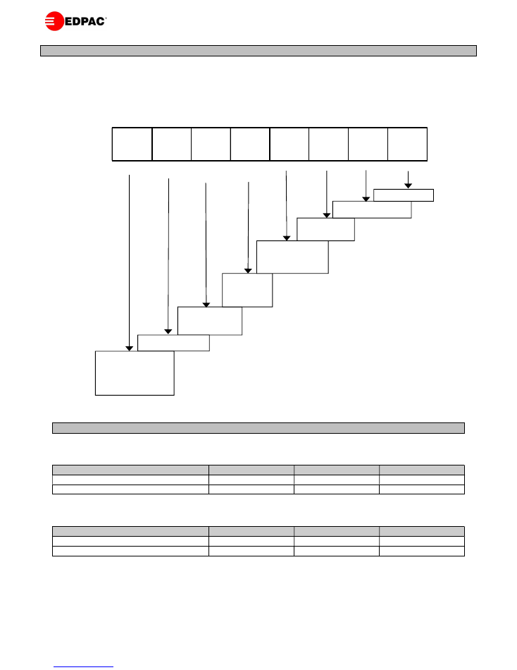
EQUIPMENT NOMENCLATURE
D
A
12
B
S
W
S
EC
NOMINAL CAPACITY
06 = 6 kW
12 = 12 kW
18 = 18 kW
A = AIR
C= CHILLED WATER
D = DOWNFLOW
S = DOWNFLOW
DISPLACEMENT
F = UPFLOW FRONT RETURN
B= UPFLOW BOTTOM
RETURN
R= UPFLOW REAR RETURN
VOLTAGE
B = 380-415/3/50
E = 220/3/60
H = 460/3/60
J = 380/3/60
S = STANDARD SCROLL
COMPRESSOR
X = CHILLED WATER
V= VARIABLE SPEED
COMPRESSOR
E = ECX OPTION
W = WITHOUT ECX
D = DUAL COOLING
S = STANDARD CONTROLS
G = GRAPHIC CONTROLS
EC = EC FAN OPTION
5
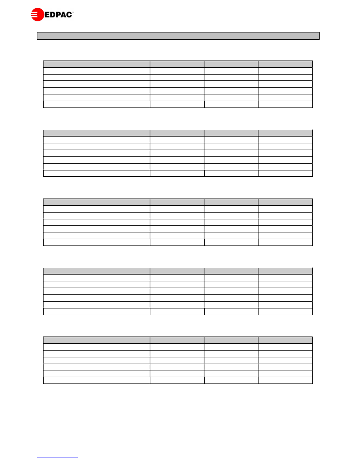
30
o
C Ambient Selection
Model
06
12
18
Condenser Model x 1
AGS 501A
AGS 501A
AGS 501B
Condenser Input Power (kW)
0.7
0.7
0.7
Free field SPL @ 10m dBA
43
43
43
Airflow (m
3
/h)
8250
8250
7850
Dimensions W x D (mm)
1050 x 825
1050 x 825
1050 x 825
Weight (kgs)
39
39
42
35
o
C Ambient Selection
Model
06
12
18
Condenser Model x 1
AGS 501A
AGS 501B
AGS 501C
Condenser Input Power (kW)
0.7
0.7
0.7
Free field SPL @ 10m dBA
43
43
43
Airflow (m
3
/h)
8250
7850
7500
Dimensions W x D (mm)
1050 x 825
1050 x 825
1050 x 825
Weight (kgs)
39
42
47
40
o
C Ambient Selection
Model
06
12
18
Condenser Model x 1
AGS 501A
AGS 501C
AGS 502A
Condenser Input Power
0.7
0.7
1.4
Free field SPL @ 10m dBA
43
43
46
Airflow (m
3
/h)
8250
7500
16500
Dimensions W x D (mm)
1050 x 825
1050 x 825
1950 x 825
Weight (kgs)
39
47
76
45
o
C Ambient Selection
Model
06
12
18
Condenser Model x 1
AGS 501A
AGS 502B
AGS 502C
Condenser Input Power (kW)
0.7
1.4
1.4
Free field SPL @ 10m dBA
43
46
46
Airflow (m
3
/h)
8250
15700
15000
Dimensions W x D (mm)
1050 x 825
1950 x 825
1950 x 825
Weight (kgs)
39
85
93
50
o
C Ambient Selection
Model
06
12
18
Condenser Model x 1
AGS 501C
AGS 502C
AGS 503B
Condenser Input Power (kW)
0.7
1.4
2.1
Free field SPL @ 10m dBA
43
46
48
Airflow (m
3
/h)
7500
15000
23550
Dimensions W x D (mm)
1050 x 825
1950 x 825
2850x825
Weight (kgs)
47
93
123
Notes:
1.
Standard Air Cooled Condensers have 4 Pole motors. For 6 Pole & 8 Pole low noise versions, consult factory.
2.
All Condensers are shipped with mounting feet. When mounted in a horizontal, Condenser models AGS 501-503 are
850mm high.
CONDENSERS – DIMENSIONS AND WEIGHTS

6
STANDARD FEATURES
Cabinet
The cabinet frames shall be constructed of formed 2.0 mm
Zintec steel sections. Paint finish is Epoxy Powder Coated with
an “Orange Peel” textured finish. Interior panels to be
manufactured from galvanised steel in all cases. Exterior
panels are to be as cabinet except in 1.2 mm Zintec. Paint
Colour to be RAL 9018. The front panels shall be fastened to
the frame using quarter turn fasteners. Side panels shall be
secured to the frame using chrome plated screws. All panels
shall be flush fitting, sealed to the frame sections with closed
cell foam and insulated with a non-shedding material, which
shall be non-combustible, when tested in accordance with B.S.
476 Part 6 and 7. The units shall be fully accessible and
serviceable from the front.
Cooling Coil
The cooling coils shall be multi-row constructed from 10mm
O/D copper tubes with aluminium fins. Large surface areas
shall ensure high sensible heat ratios and low airside pressure
drops, resulting in reduced fan power requirements and noise
levels. All DX coils shall be tested to 25 bar.
DX Units
Each unit shall have 2 independent refrigerant circuits, each
with a liquid distributor, expansion valve, sight glass and filter
drier.
Fans
Large, low speed, double inlet, double width fans with forward
curved impellers and “sealed for life” self-aligning bearings
shall be used to minimize noise levels. Fans are belt driven. All
units have twin fans on a common shaft. The fan/motor
assembly is on a separate isolated deck.
Twin Belts
Twin grooved pulleys and twin belts giving a fixed speed are
provided for each fan assembly
.
Motors
The motor shall comply with IP55 TEFC insulated to Class F.
Filtration
The filters shall be 100mm thick disposable pleated panel filter
rated G4 in accordance with EN779. They shall be fitted in the
return air stream and be accessible from the front of a Upflow
unit and the top of a Downflow unit.
Compressors
Compressors shall be high efficiency hermetically sealed scroll
type. Back seating service/isolating valve, high and low
pressure switches, motor overload protection and crankcase
heaters shall be provided. The compressors shall be mounted
on resilient neoprene mountings for vibration isolation.
Electrical Panel
The electrical panel shall be constructed and assembled in
compliance with IEC standards with all components VDE
approved. All sub circuits are protected by MCB’s. The high
and low voltage sections shall be segregated and all high
voltage electrical components shall be touch safe.
Electric Heaters
Electric heaters shall have stainless steel sheathed elements
with stainless steel finning, balanced over three phases and
rated to operate at black heat. Control shall be in two stages.
Protection is by a high temperature safety cut-out stat. The stat
shall be a capillary type mounted in the airstream resettable
from the control section of the electrical panel.
Humidification
The humidifier shall be of the electrode-boiler type. Features
shall include selectable steam output and microprocessor
control with alarms and diagnostic facilities. The humidifier
control system shall allow the use of a wide range of mains
water conditions namely: inlet mains water pressure of 1-10
bar, total hardness of 15-30 French degrees & water inlet
electrical conductivity of 400-800 micro siemens. Unit shall
optimize drain down frequency for maximum operational
economy.
Microprocessor Controls
All units shall be fitted as standard with the latest Delta range
of DIN rail mounted Microprocessor Controls. The Control
System utilizes a main Microprocessor Interface Board
equipped with a set of terminals necessary to connect the Board
to the controlled devices (e.g. valves, compressors, fans,
reheats, sensors and humidifiers). All software is permanently
stored in flash RAM and is therefore protected even in the event
of a power failure. Unit software is uploaded to the
Microprocessor using a RAM key or personal computer. On
multi-unit sites this quickens unit commissioning. The software
can also be easily changed or upgraded on site by qualified
service personnel.
The Microprocessor based Terminal Unit is complete with a 4
line x 20 character backlit LCD Display, keypad and LED
Indicators allowing the user to easily set the main control
parameters (set-points, differentials and alarm thresholds) and
carry out the main working operations (on/off and displaying
controlled variables).
Main features of controller are :
Status:
The display shall indicate current temperature, current
humidity, temperature & humidity set points, cooling status,
heating status, humidification status & dehumidification status.
GUIDE SPECIFICATIONS

7
Redundancy Management & Master Control:
The controls
shall be capable of redundancy management & master control
setup / “Handshake” of groups of up to 16 units without
addition of any hardware.
Alarms:
Controls shall be capable of storing last 100 alarms,
identified by type, date stamped & indicating also the
temperature & humidity conditions when the alarm occurred &
also the setpoints of temperature & humidity when the alarm
occurred. There are 36 alarms & all alarms can be either set as
“ serious ” or “ non-serious”. A serious alarm shuts down the
unit.
Hours Thresholds:
It shall be possible to to set run hours
thresholds for major components to facilitate preventative
maintenance.
Manual Procedure:
With the unit powered off & the controls
powered on it shall be possible to check all analogue & digital
outputs & to run the devices.
Temperature & Humidity Zone setback:
It shall be possible to
create up to 4 periods in a 24 hour period with dedicated set
points of temperature & humidity.
System Auto Restart:
For startup after power failure, the unit
shall automatically restart with an ability to stagger the starting
of multiple units by setting a time delay of up to 999 seconds.
Security:
The microprocessor shall have multiple levels of
security (5 no. 4 digit passwords) to prevent unauthorized
parameter adjustment.
Time Delays:
It shall be possible to create or adjust if necessary
the unit on time delay, unit off time delay, compressor
interstage delay, compressor minimum run time, compressor
minimum stop time, heater interstage delay, winter start time
delay, temperature alarm time delay, humidity alarm time
delay, serious alarm time delay & non-serious alarm time delay.
Sensor Calibration:
It shall be possible to recalibrate the
temperature & humidity sensors in software.
Inputs / Outputs:
It shall be possible to view the current status
of all inputs & outputs while the unit is running.
Set & Hysteresis adjustment:
It shall be possible to adjust the
set & hysteresis % values of stepped outputs within the control.
BMS / BAS interfacing:
It shall be possible with the addition of
a simple communications card to communicate all Analog,
Digital & Integer variables in the following protocols : LON
FTT 10, BACnet over RS485 MSTP, BACnet over TCP/IP,
SNMP over TCP/IP, MODBUS over RS485, Metasys & OPC
Server.
Remote Display panel:
It shall be possible to connect an
additional shared LCD display which is wired back to the unit
& this remote display shall have full control access to the unit
from a distance of up to 100m.
Remote Temperature & Humidity sensing:
It shall be possible
to remotely locate the Temperature/Humidity sensor to better
meet the sites cooling needs. The sensor can be located a
distance of up to 30m from the unit.
GUIDE SPECIFICATIONS

8
OPTIONAL FEATURES
EC Plug Fans
Available instead of forward curved belt driven fans. The EC
plug fan is a backward curved fan with integrated EC
electrically commutated motor which is controlled directly
from the microprocessor using a 0-10V output. Options on
setup are :
Unit is set up with a discrete fan speed based on a fixed 0-10V
output to the EC motor based on the design point of operation
of the fan. This is the default setting on units shipped.
Unit set up to track the cooling control temperature band with
set voltage limits whereby max voltage / fan air volume is at
set point plus control band & min voltage / fan air volume at
set point. Max air volume is typically design air volume & min
air volume is around 60% for chilled water units. This is
something that can be proven on site. Minimum value needs
to ensure there are no hot spots due to lack of airflow & that
there is no loss of sensible cooling capacity to latent cooling
capacity at the cooling coil.
Unit set up to give a reduced fan air volume in
dehumidification mode to conserve energy in
dehumidification
while
quickly
achieving
the
dehumidification effect at the cooling coil. This output voltage
is again user selectable.
Unit is set up via an underfloor pressure transducer to give a
fixed underfloor pressure all the time. Underfloor pressure
setpoint is input through the unit user display.
3 Stage Reheat
Available in lieu of 2 stage by adding an electrical contactor
& configuring the software to 3 stage.
Proportional Electric Reheat
Units shall be fitted with electric reheat controlled by a
thyristor giving a fully proportional 0-10V output of the reheat
capacity.
Hot Water Reheat
Units shall be fitted with a Low Pressure Hot Water (LPHW)
heating coil in place of the standard electrical heating. Water
flow through the coil is controlled by a 2 or 3 way modulating
valve. Duties of these coils are nominally the same as standard
electric heating, based on flow and return hot water
temperatures of 82°C and 71°C respectively.
Cleanable Humidifier Cylinder
Humidifier cylinder is servicable whereas standard humidifier
cylinder is disposable.
Low Conductivity Humidifier Cylinder
Disposable type but for water supply with low electrical
conductivity.
Upsized Fan Motors
For applications where fan power requirements exceed the
capacity of the standard motors, an upsized motor can be
fitted. Standard unit ESP is 75 Pa. Units can normally be
upgraded to 200 Pa or 400 Pa. In these instances please advise
the factory on ESP Pa required.
Floor Stand
Floorstands are shipped flat-pack and need to be assembled on
site. They are suitable for raised floor heights of 150mm to
600mm. The legs are notched at 50mm intervals for cutting
on site. There is also a final adjustment on the foot of +/-
50mm. Scoops are also available as an option with the
floorstand. Floorstands and scoops are manufactured from
galvanized steel.
Damper & On/Off Actuator Kit
Addition of a damper & on/off actuator shipped loose which
can be integrated into floorstand of downflow unit & to
discharge of upflow unit. Actuator powered from unit
electrical panel.
Air Discharge Plenum
For Upflow units which are to be installed in a freeblow
situation. Plenum consists of an insulated sheet metal
assembly with 3 discharge grilles. Grilles are double deflector
type. Plenum colour will match unit colour. Plenums can also
be manufactured as 1 way or 2 way discharge, please consult
factory.
3 way discharge plenum complete with up to F9 rigid
bag filters.
Plenum is mounted on top of unit. Plenum is 1000mm high
with a 292mm long F9 rigid bag filter. Plenum has a diffusion
section and 3 no. Air outlet grilles. Grilles on the front and 2
sides. It is also possible to have the F8/F9 discharge section on
its own, plenum is 400mm high.
Rear Return
For upflow units. Required when unit is located in a service
area outside the conditioned space. Fan deck is turned through
180 degrees. Return air is taken in the rear. Rear panel
generally has a duct connection and filters are withdrawable
from outside the unit.
Bottom return
For upflow units. Required if air is returned from a floor void.
Bottom of unit is opened up and base components are mounted
on rails. Filters cannot be fitted in unit and are shipped loose
for installation beneath the unit on site.
GUIDE SPECIFICATIONS

9
Return Air Attenuator 500mm high
.
Attenuator mounted on top of downflow unit. Attenuators
have internal baffles and provide 8-10 db reduction on
airborne noise.
F5/6/7 Panel Filters
Upgrade of standard G4 disposable panel filters to F5/6/7
disposable panel filters.
G2 Pre-filter with G4 Main Filter
100mm G4 disposable filter replaced with 50mm G2
disposable plus 50mm G4 disposable filter.
Washable Filters
Upgrade of standard disposable 100mm G4 disposable filters
to washable 50mm G3 type plus 50mm G4 disposable filter.
Filter Clog
An additional pressure differential switch mounted in the unit
to sense airside pressure drop across the filters. Once the
pressure drop is exceeded a filter clog (filter change) alarm is
generated.
Different Unit Colour
Units can be manufactured in a different colour to the standard
RAL 9018. RAL number to be specified.
Double Skin Panels
All units. Inner perforated galvanized steel or solid painted or
unpainted galvanized steel.
Fresh Air Connection
Units can be supplied with a fresh air inlet connection and
disposable G4 filter. This will admit approximately 3-5% of
the recirculated air volume.
Hot Gas Bypass
Hot gas bypass line including hot gas bypass valve fitted to
provide capacity control in low load situations.
Liquid Receiver
Liquid receiver fitted in unit base of indoor unit. Receiver is
complete with rotalock valve on the discharge.
Oil Separator
Oil separator fitted in indoor unit to prevent migration of oil
away from compressor.
Compressor Acoustic Jacket
High mass barrier insulation to reduce compressor noise.
Condensate Pump
Where, due to location, it is not possible to gravity drain units,
a condensate pump can be fitted to collect any condensate and
pump it to the nearest convenient drain point (pump duty is 6
l/min Vs 6 m head). A cheaper cold condensate pump is
available for units without humidifiers.
Handshake - Autosequence / Autorotate
For interconnection of up to 16 units. Interconnection by
means of a shielded twisted pair cable from interface board to
interface board between units. This shall provide N+1 with one
unit always in standby in case of duty unit failure. Standby unit
shall be rotated over time. Changeover shall be set between 1-
168 hours (1 hour – 1 week). In case of high temperature alarm
standby unit shall run & revert to standby once temperature is
corrected. In the group of up to 16 unit, any number can be
running & any number can be set in standby.
Smoke Detector
A smoke detector shall be provided & mounted in the return
air path to interface with the unit controls and generate an
alarm.
Fire Detector
A fire detector shall be provided & mounted in the return air
path to interface with the unit controls and generate an alarm.
Fire Stat
A fire stat shall be provided & mounted in the return air path
within the unit to interface with the unit controls and indicate
an alarm.
Water Detection – Point Type
Consists of a water detection module mounted in unit & point
sensor which can be placed in unit or under the floor. Multiple
point sensors can be placed in series with each other. A cable
type water warning is also available.
RS 485 Communications Card
Serial interface card for Microprocessor board. For BMS
setup. Can communicate on Delta 2 own Protocol & Modbus
without an external Gateway.
BACnet over RS 485
Serial interface card for Microprocessor board. For BMS
setup. Runs on BACnet protocol over RS 485. Final setup by
BMS system integrator.
BACnet over TCP/IP
Serial interface card for Microprocessor board. For BMS
setup. Runs on BACnet protocol over TCP/IP. Final setup by
BMS system integrator.
GUIDE SPECIFICATIONS

10
SNMP over TCP/IP
Serial interface card for Microprocessor board. For BMS
setup. Runs on SNMP protocol over TCP/IP. Final setup by
BMS system integrator.
LON Communication Card
Serial interface card for Microprocessor board. For BMS
setup. Runs on LON FTT 10 protocol. Final setup by LON
system integrator.
TREND Communication Card
Serial interface card for Microprocessor board. For BMS setup
on TREND BMS. Final setup by TREND system integrator.
Condenser Factory Wired Disconnect
Factory wired disconnect fitted to condenser.
MCB and Contactor Condenser Control
MCB and contactor fitted in unit per condenser providing
condenser on/off control interlocked with compressor.
MCB, Contactor and Pressure Switch Condenser
Control
MCB, contactor and pressure switch fitted in unit per
condenser fan providing condenser on/off based on
condenser fan activated on pressure switch pressure signal.
MCB, Contactor and Pressure Activated Fan Speed
Control
MCB and contactor per condenser fan. Condenser fans are all
220V/1 Ph and unit has a single or dual input Johnson
pressure activated fan speed control.
Condenser Fan Control with VSD
Uses a VSD to give a 0-10V proprtional output to the
condenser to maintain refrigerant head pressure control.
Graphic Display
An optional Graphical Terminal Unit is also available. This is
a graphical display, LED Backlit with 132 x 64 pixel graphical
resolution.
GUIDE SPECIFICATIONS
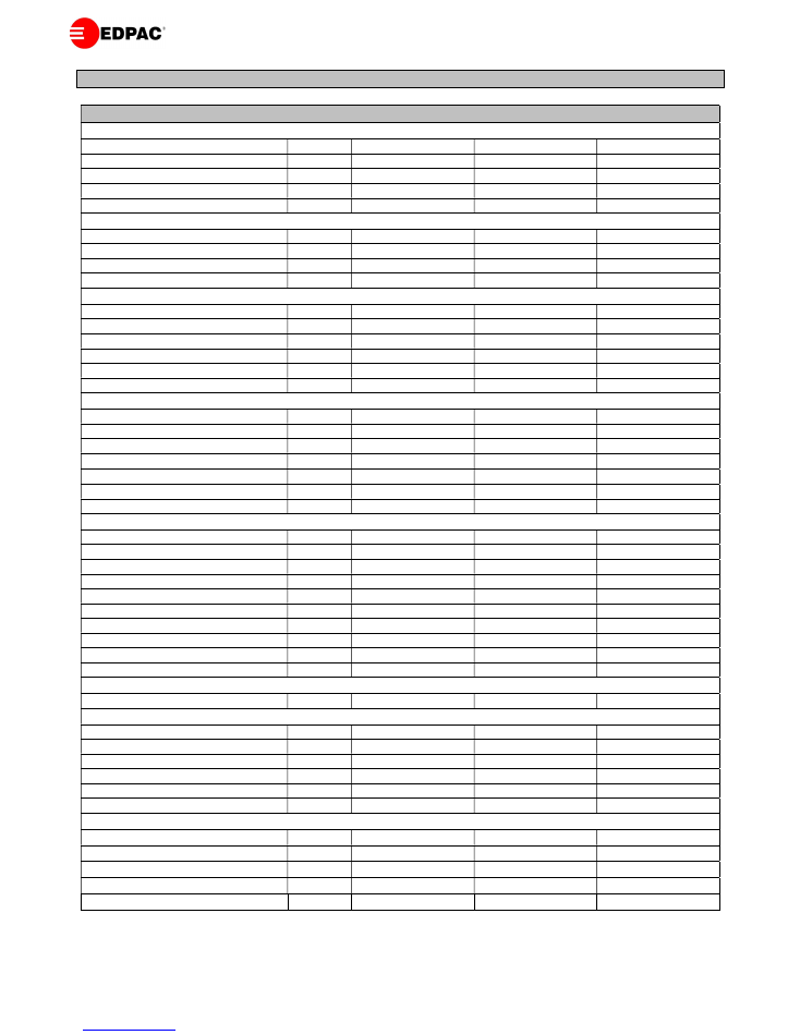
11
Model
06
12
18
Air Side Data
Air Volume
m
3
/hr
1800
3600
5400
m
3
/s
0.5
1.0
1.5
External Static Pressure ESP
Pa
75
75
75
No. of Fans
No.
1
1
1
Fan Motor
kW
0.55
1.10
1.50
Optional EC Plug Fan
Quantity
No.
1
1
1
Fan Diameter
mm
350
400
450
Fan Motor
kW
1.23
1.40
1.45
Fan Absorbed Power
kW
0.2
0.5
0.9
Filter Data
Downflow Filter Size
mm
495 x 535
495 x 535
495 x 695
Downflow Filter Quantity
No.
2
2
2
Upflow Filter Size
mm
775 x 300
775 x 300
775 x 460
Upflow Filter Quantity
No.
1
1
1
Filter Depth
mm
100
100
100
Filter Efficiency
-
G4
G4
G4
Water Side Data
Control Valve Size
mm
20
25
25
Control Valve Kv
-
4.0
6.3
6.3
Chilled Water F&R Pipe Size
mm
22
28
28
Cooling Coil Data
Coil Face Area – DX and C. Water
m
2
0.4
0.6
0.6
Coil Rows
No.
4
4
4
Coil Drain Connection BSPF
inch
1
1
1
Air Cooled Units
Discharge Line Pipe Size
mm
16
16
16
Liquid Line Pipe Size
mm
12
12
12
Condenser Conns. Inlet/Outlet 30°C
mm
22/16
22/16
28/22
Condenser Conns. Inlet/Outlet 35°C
mm
22/16
28/22
28/22
Condenser Conns. Inlet/Outlet 40°C
mm
22/16
28/22
35/28
Condenser Conns. Inlet/Outlet 45°C
mm
22/16
35/28
35/28
Condenser Conns. Inlet/Outlet 50°C
mm
28/22
35/28
35/28
Scroll Compressor – 50Hz
-
ZR34
ZR61
ZR81
Scroll Compressor – 60Hz
-
ZR28
ZR48
ZR72
Compressor Quantity
No.
1
1
1
Noise Data
Free field SPL @ 3m
dBA
52
55
57
Optional Humidifier Data
Capacity
kg/hr
2
2
3
Inlet Connection BSPM
inch
1
1
1
Drain Connection BSPM
inch
1
1
1
Water Feed Pressure
Bar
1-10
1-10
1-10
Water Feed Electrical Conductivity
μS
400 – 800
400 – 800
400 – 800
French Degrees Water Hardness
-
15-30
15-30
15-30
Optional Electric Reheat Data
Capacity - 400V/3Ph/50Hz
kW
7.5
9.6
9.6
Capacity - 220V/3Ph/60Hz
kW
7.5
9.6
9.6
Capacity - 380V/3Ph/60Hz
kW
6.8
8.7
8.7
Capacity - 460V/3Ph/60Hz
kW
10.0
12.8
12.8
No. of Stages
No.
2
2
2
Notes:
1.
Indoor unit free field SPL dBA levels are measured at 3m.
2.
For correct installation pipe sizes refer to refrigerant and water pipe sizing tables.
GENERAL ENGINEERING DETAILS
12
M
8
1
2
3
4
5
6
7
8
9
10
12
13
14
15
11
Suction
Line
Discharge
Line
Liquid
Line
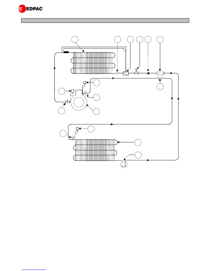
System Components
1.
Evaporator Coil.
2.
Liquid Distributor.
3.
Thermostatic Expansion Valve (externally equalized).
4.
Liquid Line Solenoid Valve (optional).
5.
Liquid Sight Glass (including moisture indicator).
6.
Filter Drier.
7.
Compressor.
8.
Compressor Service Valves.
9.
High Pressure Switch (manual reset).
10.
Low Pressure Switch (automatic reset).
11.
Check Valve (See Note).
12.
Fan speed Controller (pressure operated head pressure control, if fitted).
13.
Pressure relief Valve (See Note).
14.
Air Cooled Condenser.
15.
Liquid Receiver (See Note).
Note:
1.
Items 11, 13 and 15 are supplied by others and field fitted by others.
AIR COOLED SYSTEM SCHEMATIC
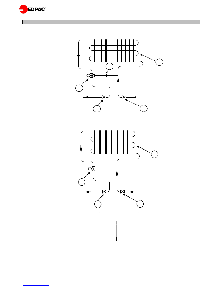
13
3 Way Valve System
2 Way Valve System
3 Way Valve System
2 Way Valve System
1
Chilled Water Coil
Chilled Water Coil
2
Balancing Orifice
2 Way Modulating Valve
3
3 Way Modulating Valve
Isolating Valves
4
Isolating Valves
Note:
Isolating valves are field fitted by others.
CHILLED WATER SYSTEM SCHEMATIC
2
3
Chilled Water Return
Chilled Water Flow
4
4
M
1
2
Chilled Water Return
Chilled Water Flow
3
3
M
1
14
AIR COOLED UNITS - COOLING CAPACITIES 60Hz
Notes:
1. Capacities are based on R407C refrigerant.
2. For capacities at other conditions, please refer to the product selection program.
3. Units are also available for R134A applications, please contact the factory.
4. For R410A, please refer to the R410A catalogue or product selection program.
5. Cooling performances are gross. For nett capacities please deduct motor power as outlined on general engineering details page.
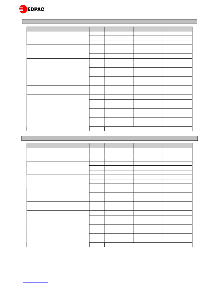
AIR COOLED UNITS – COOLING CAPACITIES 50Hz
Model
06
12
18
Air On: 22
o
C, 45% RH
Total Capacity
kW
7.2
13.0
17.4
Sensible Capacity
kW
6.8
12.3
16.3
Air On: 22
o
C, 50% RH
Total Capacity
kW
7.2
13.0
17.4
Sensible Capacity
kW
6.6
11.9
15.8
Air On: 24
o
C, 45% RH
Total Capacity
kW
7.5
13.6
18.1
Sensible Capacity
kW
6.8
12.1
16.3
Air On: 24
o
C, 50% RH
Total Capacity
kW
7.5
13.6
18.1
Sensible Capacity
kW
6.6
11.9
16.0
Scroll Compressor
-
ZR34
ZR61
ZR81
Compressor Input Power
kW
2.3
4.0
5.3
Airflow
m
3
/s
0.5
1.0
1.5
No. of Fans
No.
1
1
1
Fan Motor
kW
0.55
1.10
1.50
No. of Motors
No.
1
1
1
Electric Reheat
kW
6.0
6.0
9.6
No. of Steps
No.
2
2
2
Humidifier Capacity
kg/hr
2
2
3
Humidifier Power
kW
1.5
1.5
2.2
Model
06
12
18
Air On: 22
o
C, 45% RH
Total Capacity
kW
7.3
12.6
18.4
Sensible Capacity
kW
6.9
11.9
17.3
Air On: 22
o
C, 50% RH
Total Capacity
kW
7.3
12.6
18.4
Sensible Capacity
kW
6.7
11.5
16.7
Air On: 24
o
C, 45% RH
Total Capacity
kW
7.6
13.1
19.1
Sensible Capacity
kW
6.9
11.6
17.2
Air On: 24
o
C, 50% RH
Total Capacity
kW
7.6
13.1
19.1
Sensible Capacity
kW
6.7
11.5
16.9
Scroll Compressor
-
ZR28
ZR48
ZR72
Compressor Input Power
kW
2.4
3.8
5.6
Airflow
m
3
/s
1.5
1.0
1.5
No. of Fans
No.
1
1
1
Fan Motor
kW
0.55
1.10
1.50
No. of Motors
No.
1
1
1
Electric Reheat
kW
8.0
8.0
12.8
No. of Steps
No.
2
2
2
Humidifier Capacity
kg/hr
2
2
3
Humidifier Power
kW
1.5
1.5
2.9
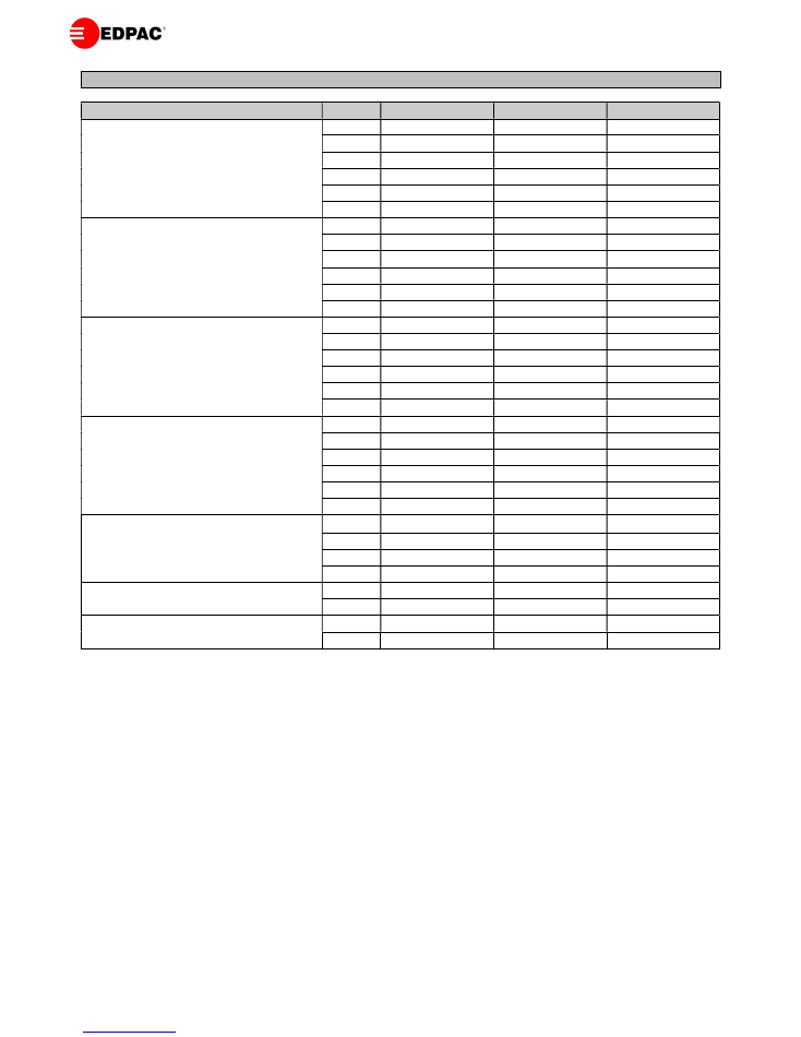
15
Model
06
12
18
Air On: 22
o
C, 45% RH
Total Capacity
kW
7.0
12.2
18.3
Sensible Capacity
kW
7.0
12.1
18.3
S.H.R.
-
1.00
0.99
1.00
Chilled Water Flow
l/s
0.3
0.5
0.7
Unit Pressure Drop
kPa
16
21
49
Air On: 22
o
C, 50% RH
Total Capacity
kW
7.0
12.2
18.3
Sensible Capacity
kW
6.4
12.1
18.3
S.H.R.
-
0.91
1.00
1.00
Chilled Water Flow
l/s
0.3
0.5
0.7
Unit Pressure Drop
kPa
16
21
49
Air On: 24
o
C, 45% RH
Total Capacity
kW
8.2
14.2
21.4
Sensible Capacity
kW
7.5
14.1
21.3
S.H.R.
-
0.91
0.99
1.00
Chilled Water Flow
l/s
0.3
0.6
0.8
Unit Pressure Drop
kPa
20
27
60
Air On: 24
o
C, 50% RH
Total Capacity
kW
7.0
14.2
21.4
Sensible Capacity
kW
6.5
12.7
18.8
S.H.R.
-
0.93
0.89
0.88
Chilled Water Flow
l/s
0.3
0.6
0.8
Unit Pressure Drop
kPa
16
27
60
Airflow
m
3
/s
0.5
1.0
1.5
No. of Fans
No.
1
1
1
Fan Motor
kW
0.55
1.10
1.50
No. of Motors
No.
1
1
1
Electric Reheat
kW
6.0
6.0
9.6
No. of Steps
No.
2
2
2
Humidifier Capacity
kg/hr
2
2
3
Humidifier Power
kW
1.5
1.5
2.2
Notes:
1. Capacities are based on a 6
o
C chilled water coil entering temperature & the tabulated flow rate.
2. Cooling performances are gross. For nett capacities please deduct motor power as outlined on general engineering details page.
3. For cooling performance at other conditions, please refer to the product selection program.
4. Electric reheat capacity is for 400V/3Ph/50Hz. For other voltages, see P11.
CHILLED WATER UNITS – COOLING CAPACITIES 50/60Hz
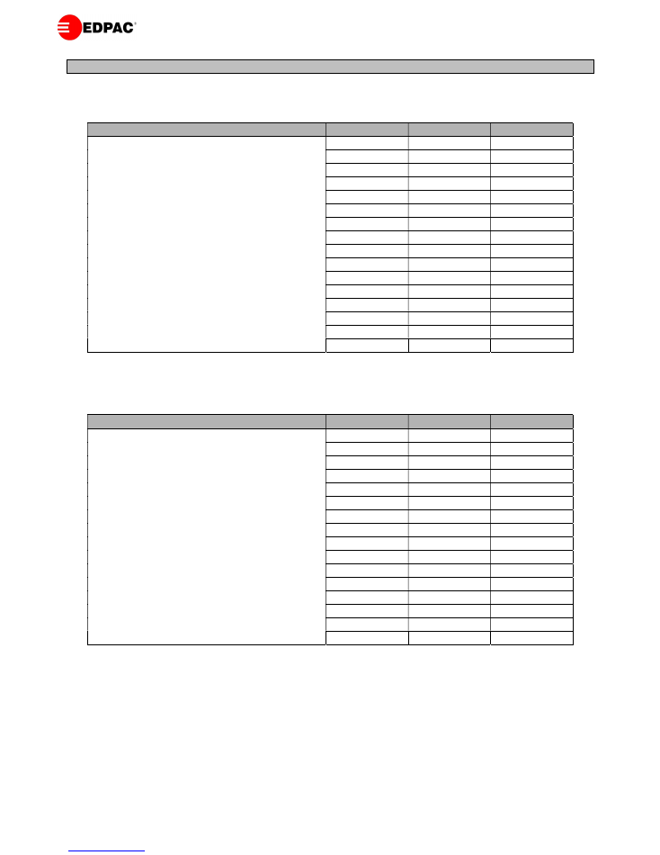
16
400V/3PH/50Hz
Model
06
12
18
Controls FLA
1.0
1.0
1.0
Fans FLA
1.5
2.7
3.6
Reheat FLA
8.7
8.7
13.9
Humidifier FLA
2.2
2.2
3.2
Scroll Compressor FLA
4.4
7.3
10.1
Condenser FLA 30˚C
3.0
3.0
3.0
Condenser FLA 35˚C
3.0
3.0
3.0
Condenser FLA 40˚C
3.0
3.0
6.0
Condenser FLA 45˚C
3.0
6.0
6.0
Condenser FLA 50˚C
3.0
6.0
9.0
Max Unit FLA - Cooling only
9.9
17.0
23.7
Max Fuse FLA
15.0
30.0
35.0
Max Unit FLA - Cooling & Dehumidification
18.6
25.7
37.6
Max Fuse FLA
30.0
40.0
50.0
Max Unit FLA - Heating and Humidification
13.4
14.6
21.7
Max Fuse FLA
20.0
20.0
30.0
220V/3PH/60Hz
Model
06
12
18
Controls FLA
1.0
1.0
1.0
Fans FLA
2.7
4.9
6.6
Reheat FLA
15.8
15.8
25.3
Humidifier FLA
4.0
4.0
5.8
Scroll Compressor FLA
7.2
12.4
16.6
Condenser FLA 30˚C
3.9
3.9
3.9
Condenser FLA 35˚C
3.9
3.9
3.9
Condenser FLA 40˚C
3.9
3.9
7.8
Condenser FLA 45˚C
3.9
7.8
7.8
Condenser FLA 50˚C
3.9
7.8
11.7
Max Unit FLA - Cooling only
14.8
26.1
35.9
Max Fuse FLA
25.0
45.0
55.0
Max Unit FLA - Cooling & Dehumidification
30.6
41.9
61.2
Max Fuse FLA
45.0
65.0
80.0
Max Unit FLA - Heating and Humidification
23.5
25.7
38.7
Max Fuse FLA
35.0
35.0
50.0
Notes:
1.
FLA = Full Load Amps.
2.
Unit maximum FLA is the total of the components, which operate during maximum electrical load conditions.
3.
Max FLA of cooling only unit: FLA = Controls + Fans + Compressor + Condenser.
4.
Max FLA of unit with reheat in dehumidification: FLA = Controls + Fans + Reheat + Compressor + Condenser.
5.
Max FLA of units with heating & humidifiers: FLA = Controls + Fans + Reheat + Humidifier.
6.
Max Fuse is the recommended value of the unit overcurrent protection device.
ELECTRICAL DETAILS – AIR COOLED UNITS
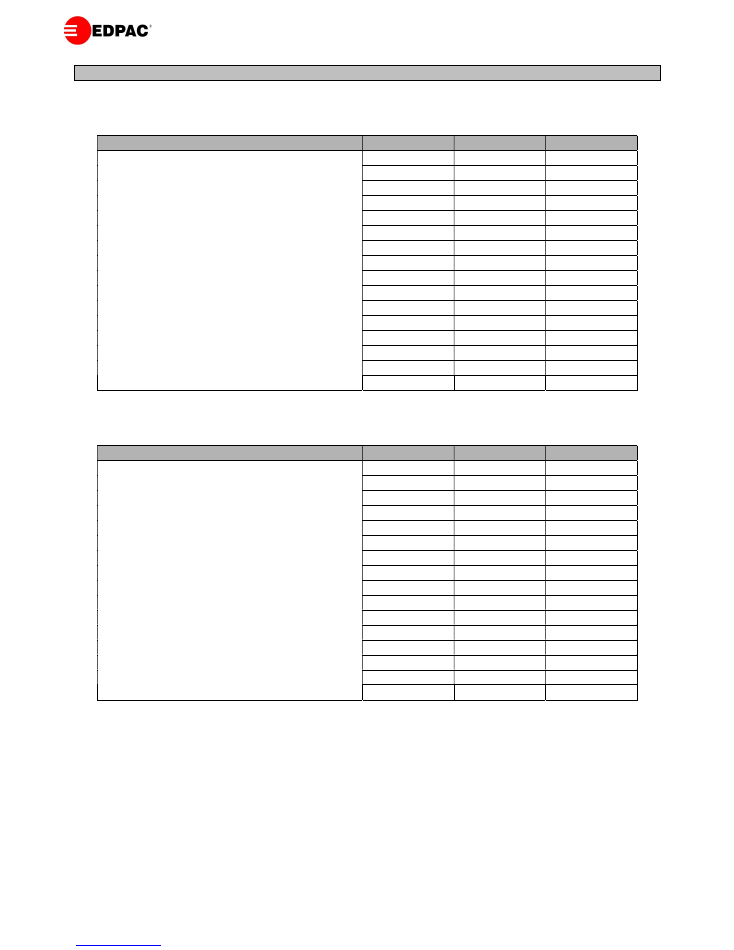
17
380V/3PH/60Hz
Model
06
12
18
Controls FLA
1.0
1.0
1.0
Fans FLA
1.6
2.9
3.8
Reheat FLA
8.2
8.2
13.2
Humidifier FLA
2.3
2.3
3.4
Scroll Compressor FLA
3.6
6.2
8.3
Condenser FLA 30˚C
3.9
3.9
3.9
Condenser FLA 35˚C
3.9
3.9
3.9
Condenser FLA 40˚C
3.9
3.9
7.8
Condenser FLA 45˚C
3.9
7.8
7.8
Condenser FLA 50˚C
3.9
7.8
11.7
Max Unit FLA - Cooling only
10.1
17.9
24.8
Max Fuse FLA
15.0
30.0
35.0
Max Unit FLA - Cooling & Dehumidification
18.3
26.1
38.0
Max Fuse FLA
25.0
40.0
45.0
Max Unit FLA - Heating and Humidification
13.1
14.4
21.4
Max Fuse FLA
20.0
20.0
30.0
460V/3PH/60Hz
Model
06
12
18
Controls FLA
1.0
1.0
1.0
Fans FLA
1.3
2.3
3.1
Reheat FLA
10.1
10.1
16.1
Humidifier FLA
1.9
1.9
2.8
Scroll Compressor FLA
4.3
7.4
10.0
Condenser FLA 30˚C
1.2
1.2
1.2
Condenser FLA 35˚C
1.2
1.2
1.2
Condenser FLA 40˚C
1.2
1.2
2.4
Condenser FLA 45˚C
1.2
2.4
2.4
Condenser FLA 50˚C
1.2
2.4
3.6
Max Unit FLA - Cooling only
7.8
12.9
17.3
Max Fuse FLA
15.0
25.0
30.0
Max Unit FLA - Cooling & Dehumidification
17.7
22.8
33.2
Max Fuse FLA
30.0
35.0
50.0
Max Unit FLA - Heating and Humidification
14.3
15.3
23.0
Max Fuse FLA
20.0
25.0
40.0
Notes:
1.
FLA = Full Load Amps.
2.
Unit maximum FLA is the total of the components, which operate during maximum electrical load conditions.
3.
Max FLA of cooling only unit: FLA = Controls + Fans + Compressor + Condenser.
4.
Max FLA of unit with reheat in dehumidification: FLA = Controls + Fans + Reheat + Compressor + Condenser.
5.
Max FLA of units with heating & humidifiers: FLA = Controls + Fans + Reheat + Humidifier.
6.
Max Fuse is the recommended value of the unit overcurrent protection device.
ELECTRICAL DETAILS – AIR COOLED UNITS
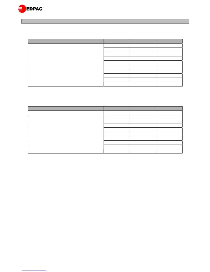
18
400V/3PH/50Hz
Model
06
12
18
Controls FLA
1.0
1.0
1.0
Fans FLA
1.5
2.7
3.6
Reheat FLA
8.7
8.7
13.9
Humidifier FLA
2.2
2.2
3.2
Max Unit FLA - Cooling only
2.5
3.7
4.6
Max Fuse FLA
10 .0
10.0
10.0
Max Unit FLA - Cooling & Dehumidification
11.2
12.4
18.5
Max Fuse FLA
20.0
20.0
25.0
Max Unit FLA - Heating and Humidification
13.4
14.6
21.7
Max Fuse FLA
20.0
20.0
30.0
220V/3PH/60Hz
Model
06
12
18
Controls FLA
1.0
1.0
1.0
Fans FLA
2.7
4.9
6.6
Reheat FLA
15.8
15.8
25.3
Humidifier FLA
4.0
4.0
5.8
Max Unit FLA - Cooling only
3.7
5.9
7.6
Max Fuse FLA
10.0
15.0
20.0
Max Unit FLA - Cooling & Dehumidification
19.5
21.7
32.9
Max Fuse FLA
35.0
30.0
45.0
Max Unit FLA - Heating and Humidification
23.5
25.7
38.7
Max Fuse FLA
30.0
35.0
50.0
Notes:
1.
FLA = Full Load Amps.
2.
Unit maximum FLA is the total of the components, which operate during maximum electrical load conditions.
3.
Max FLA of cooling only unit: FLA = Controls + Fans.
4.
Max FLA of unit with reheat in dehumidification: FLA = Controls + Fans + Reheat.
5.
Max FLA of units with heating & humidifiers: FLA = Controls + Fans + Reheat + Humidifier.
6.
Max Fuse is the recommended value of the unit overcurrent protection device.
ELECTRICAL DETAILS – CHILLED WATER UNITS

19
380V/3PH/60Hz
Model
06
12
18
Controls FLA
1.0
1.0
1.0
Fans FLA
1.6
2.8
3.8
Reheat FLA
8.2
8.2
13.2
Humidifier FLA
2.3
2.3
3.4
Max Unit FLA - Cooling only
2.6
3.8
4.8
Max Fuse FLA
10.0
10.0
10.0
Max Unit FLA - Cooling & Dehumidification
10.8
12.1
18.0
Max Fuse FLA
15.0
20.0
25.0
Max Unit FLA - Heating and Humidification
13.1
14.4
21.4
Max Fuse FLA
20.0
20.0
30.0
460V/3PH/60Hz
Model
06
12
18
Controls FLA
1.0
1.0
1.0
Fans FLA
1.3
2.3
3.1
Reheat FLA
10.1
10.1
16.0
Humidifier FLA
1.9
1.9
2.8
Max Unit FLA - Cooling only
2.3
3.3
4.1
Max Fuse FLA
10.0
10.0
10.0
Max Unit FLA - Cooling & Dehumidification
12.4
13.4
20.1
Max Fuse FLA
20.0
20.0
25.0
Max Unit FLA - Heating and Humidification
14.3
15.3
22.9
Max Fuse FLA
20.0
20.0
30.0
Notes:
1.
FLA = Full Load Amps.
2.
Unit maximum FLA is the total of the components, which operate during maximum electrical load conditions.
3.
Max FLA of cooling only unit: FLA = Controls + Fans.
4.
Max FLA of unit with reheat in dehumidification: FLA = Controls + Fans + Reheat.
5.
Max FLA of units with heating & humidifiers: FLA = Controls + Fans + Reheat + Humidifier.
6.
Max Fuse is the recommended value of the unit overcurrent protection device.
ELECTRICAL DETAILS – CHILLED WATER UNITS