Full Text Searchable PDF User Manual
Roofpak
®
Singlezone Heating and Cooling Units Models RPS\RDT\RFS\
RCS\RPE\RDE
Roofpak
®
Applied Rooftop Systems Air Handling Units Model RAH
Self-Contained Air Conditioning Systems Models SWT\SWP
Rebel
®
Commercial Packaged Rooftop Systems Model DPS
Maverick
®
II Commercial Packaged Rooftop Systems Models MPS
Pathfinder
®
Air-Cooled Screw Chiller Models AWS/AWV
Trailblazer
®
Air-Cooled Scroll Compressor Chiller Models AGZ-D/AGZ-E
Installation and Operation Manual
IM 1005-3
Group:
Controls
Part Number:
IM 1005
Date:
November 2016
MicroTech
®
III Unit Controller
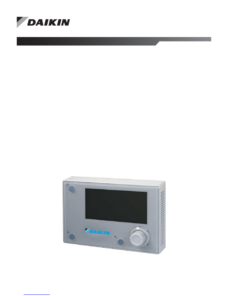
Remote User Interface

IM 1005-3 • MICROTECH III REMOTE USER INTERFACE 2
www.DaikinApplied.com
Table of Contents
Table of Contents
Introduction . . . . . . . . . . . . . . . . . . . . . . . . . . . . . . . . . . 3
General Information . . . . . . . . . . . . . . . . . . . . . . . . . . 3
Product Information. . . . . . . . . . . . . . . . . . . . . . . . . . . 3
Revision History . . . . . . . . . . . . . . . . . . . . . . . . . . . . . 3
Notice . . . . . . . . . . . . . . . . . . . . . . . . . . . . . . . . . . . . . 3
Limited Warranty . . . . . . . . . . . . . . . . . . . . . . . . . . . . . 3
Reference Documents . . . . . . . . . . . . . . . . . . . . . . . . 4
Features . . . . . . . . . . . . . . . . . . . . . . . . . . . . . . . . . . . 4
Component Data . . . . . . . . . . . . . . . . . . . . . . . . . . . . . 4
Dimensions . . . . . . . . . . . . . . . . . . . . . . . . . . . . . . . 4
Display . . . . . . . . . . . . . . . . . . . . . . . . . . . . . . . . . . . 4
Environmental Conditions . . . . . . . . . . . . . . . . . . . . 4
Installation . . . . . . . . . . . . . . . . . . . . . . . . . . . . . . . . . . . 5
Pre-Installation . . . . . . . . . . . . . . . . . . . . . . . . . . . . . . 5
Location Considerations . . . . . . . . . . . . . . . . . . . . . 5
Mounting Surfaces . . . . . . . . . . . . . . . . . . . . . . . . . . 5
Parts. . . . . . . . . . . . . . . . . . . . . . . . . . . . . . . . . . . . . 5
Installation . . . . . . . . . . . . . . . . . . . . . . . . . . . . . . . . . . 5
Mounting . . . . . . . . . . . . . . . . . . . . . . . . . . . . . . . . . 5
Wiring the Remote User Interface. . . . . . . . . . . . . . . . 7
Daisy-Chain Connection . . . . . . . . . . . . . . . . . . . . . 7
Direct Connection . . . . . . . . . . . . . . . . . . . . . . . . . . 8
Operator's Guide . . . . . . . . . . . . . . . . . . . . . . . . . . . . . 9
Using the Remote User Interface . . . . . . . . . . . . . . . . 9
Hardware Features . . . . . . . . . . . . . . . . . . . . . . . . . 9
Keypad/Display Features. . . . . . . . . . . . . . . . . . . . . 9
Alarms . . . . . . . . . . . . . . . . . . . . . . . . . . . . . . . . . . 10
Passwords . . . . . . . . . . . . . . . . . . . . . . . . . . . . . . . 10
Configuration
. . . . . . . . . . . . . . . . . . . . . . . . . . . . . . . 10
Customize User Preferences . . . . . . . . . . . . . . . . . 10
Synchronize with MicroTech III Unit Controller . . . 11
Firmware Upgrade Procedure . . . . . . . . . . . . . . . . 12
Troubleshooting . . . . . . . . . . . . . . . . . . . . . . . . . . . . . 13
General Troubleshooting. . . . . . . . . . . . . . . . . . . . . . 13
Frequently Asked Questions . . . . . . . . . . . . . . . . . . 13
Helpful Tips . . . . . . . . . . . . . . . . . . . . . . . . . . . . . . . . 13
Introduction
www.DaikinApplied.com
3
IM 1005-3 • MICROTECH III REMOTE USER INTERFACE
Introduction
General Information
This manual contains the information needed to install and
operate the remote user interface for use with MicroTech
®
III
Applied Air and Air-Cooled Scroll Chiller unit controllers from
Daikin Applied.
For technical support on rooftop or self-contained unit
controllers, contact the Daikin Applied Air Technical Response
Center at 844-521-3928 (techresponseaah@daikinapplied.com).
For chiller unit controller support, contact the Daikin Applied
Chiller Technical Response Center at 540-248-9239
(techresponse@daikinapplied.com).
Product Information
The remote user interface is designed for display, system
configuration, set-up, and management of MicroTech III unit
controllers:
• Roofpak
®
Applied Packaged Rooftops
• Self-Contained Air Conditioning Systems
• Rebel
®
and Maverick
®
II Commercial Packaged Rooftops
•
Pathfinder
®
and Trailblazer
®
Air-Cooled Chillers
In addition to the unit-mounted controller keypad/display,
MicroTech III unit control systems can be equipped with
a remote user interface that handles up to eight units per
interface. The remote user interface provides access to unit
diagnostics and control adjustments similar to the unit-mounted
controller.
Revision History
IM 1005
January 2010
Initial release
IM 1005-1
September
2010
Added Daikin Trailblazer
®
chiller model
AGZ-D
IM 1005-2
March 2012
Added Rebel
®
packaged rooftop model
DPS. Updated Figure 3 with labels and
connector cables.
IM 1005-3
November 2016
Added models AWV Pathfinder
®
chiller and AGZ-E Trailblazer
®
chiller,
added RJ45 direct connection option,
corrected bus wiring distance limitations,
Troubleshooting section, Daikin
branding and formatting updates
Notice
© 2016 Daikin Applied, Minneapolis MN. All rights reserved
throughout the world
Daikin Applied reserves the right to change any information
contained herein without prior notice. The user is responsible
for determining whether this product is appropriate for his or
her application.
Limited Warranty
™ ® The following are trademarks or registered trademarks
of their respective companies: Daikin Applied, Trailblazer,
Pathfinder, Maverick, Rebel, Roofpak and MicroTech III
from Daikin Applied. Consult your local Daikin Applied
representative for warranty details. To find your local Daikin
Applied representative, go to
www.DaikinApplied.com
.
Hazardous Information Messages
Recognize Safety Symbols, Words and Labels
The following symbols and labels are used throughout this
manual to indicate immediate or potential hazards. It is the
owner and installer’s responsibility to read and comply with
all safety information and instructions accompanying these
symbols. Failure to heed safety information increases the
risk of property damage and/or product damage, serious
personal injury or death. Improper installation, operation and
maintenance can void the warranty.
CAUTION
Cautions indicate potentially hazardous situations, which can
result in personal injury or equipment damage if not avoided.
Static sensitive components. Can cause equipment damage.
Discharge any static electrical charge by touching the bare
metal inside the control panel before performing any service
work. Never unplug cables, circuit board terminal blocks, or
power plugs while power is applied to the panel
WARNING
Warnings indicate potentially hazardous situations, which can
result in property damage, severe personal injury, or death if
not avoided.
DANGER
Dangers indicate a hazardous situation which will result in
death or serious injury if not avoided. Electric shock hazard.
Can cause personal injury or equipment damage. This
equipment must be properly grounded. Connections and
service to the MicroTech III unit controller must be performed
only by personnel knowledgeable in the operation of the
equipment being controlled.
NOTICE
This equipment generates, uses and can radiate radio
frequency energy and, if not installed and used in accordance
with this instruction manual, may cause interference to radio
communications. It has been tested and found to comply with
the limits for a Class A digital device, pursuant to part 15 of the
FCC rules. These limits are designed to provide reasonable
protection against harmful interference when the equipment
is operated in a commercial environment. Operation of this
equipment in a residential area is likely to cause harmful
interference in which case the user will be required to correct
the interference at his or her own expense. Daikin disclaims
any liability resulting from any interference or for the correction
thereof.
IM 1005-3 • MICROTECH III REMOTE USER INTERFACE 4
www.DaikinApplied.com
Introduction
Reference Documents
Daikin Applied
IOM 1202
Pathfinder
Chiller
Model AWS Installation,
Operation, and
Maintenance Manual
www.DaikinApplied.
com
Daikin Applied
IOM 1206
Trailblazer Chiller
Model AGZ
Installation,Operation
and Maintenance
Manual
www.DaikinApplied.
com
Daikin Applied
IOM 1242
Pathfinder
Model AWV
Chiller Installation,
Operation, and
Maintenance Manual
www.DaikinApplied.
com
Daikin Applied
OM 920
MicroTech III
unit controller for
Commercial Rooftop,
Applied Rooftop, and
Self-Contained Systems
Operations Manual
www.DaikinApplied.
com
Features
• Push-and-roll navigation wheel with an 8-line by
30-character display format
• Operating conditions, system alarms, control parameters
and schedules are monitored
• RS-485 or KNX interface for local or remote installation
• Power from controller, no additional power supply
necessary
• Supports panel mounting and wall mounting
Component Data
General
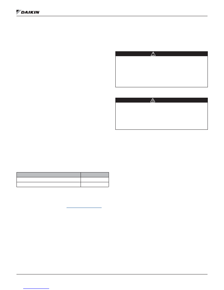
Figure 1
shows the details of the remote user
interface hardware design.
The overall physical layout includes:
• 5.7 x 3.8 x 1 in (144 x 96 x 26 mm) size
• 9.1 oz (256.7 g) weight, excluding packaging
• Plastic housing
Power
• Supplied by the MicroTech III unit controller for direct
connection
• Separate 24V DAC power supply, optional for daisy chain
connections, Max 85 mA
NOTE:
Contact either the Daikin Applied Air
Technical Response Center at 844-521-3928
(techresponseaah@daikinapplied.com) or the
Chiller Technical Response Center at 540-248-9239
(techresponse@daikinapplied.com) if a separate
power supply is desired.
Display
• LCD type FSTN
• Resolution dot-matrix 96 x 208
• Backlight blue or white, user selectable
Environmental Conditions
Operation
EC 721-3-3
Temperature
-40...158°F (-40...+70°C)
Restriction LCD
-4...140°F (-20…+60°C)
Restriction Process-Bus
-13...158°F (-25….+70°C)
Humidity
< 90% RH (no condensation)
Air pressure
Min. 10.2 psi (700 hPa),
corresponding to max. 9843 ft
(3000 m) above sea level
Figure 1: Physical Dimensions
Installation
www.DaikinApplied.com
5
IM 1005-3 • MICROTECH III REMOTE USER INTERFACE
Installation
Pre-Installation
Please be aware of the following before mounting and installing
the remote user interface.
Location Considerations
Placement of the remote user interface is necessary to
ensure proper operation. When selecting a location, avoid the
following:
• Locations that are outside the operating temperature and
humidity range (see
Environmental Conditions.
)
• Mounting on rooftop without a careful site evaluation and
confirmation
• Walls that are subject to high vibration
• Areas with high humidity exterior walls and other walls
that have a temperature differential between the two
sides
• Areas that are close to heat sources such as sunlight,
appliances, concealed pipes, chimneys, or other heat-
generating equipment
Mounting Surfaces
For surface installation, mount the remote user interface to a
flat surface such as sheet rock or plaster, control panel, or an
electrical junction box.
• If mounting onto sheet rock or plaster, use anchors, if
necessary
• For mounting in the unit controller panel, electrical
junction box, or other metal enclosure, use the supplied
magnets.
Parts
Description
Part Number
MicroTech III Remote User Interface
193408003
1,2
Connectors (using CE+ CE- connection option) 193410302
1. Note that part number 193408001 is no longer available.
2. For daisy-chaining unit controllers together, a 2-pin connector
(PN 193410302), is required
for each unit controller.
The 2-pin
connector is not required for direct-connecting unit controllers.
To find your local parts office, visit
www.DaikinApplied.com
or
call 800-37PARTS (800-377-2787).
Installation
The following section describes how to mount the remote
user interface and connect it to one or more MicroTech III unit
controllers.
CAUTION
Electrostatic discharge hazard . Can cause equipment
damage .
This equipment contains sensitive electronic components
that may be damaged by electrostatic discharge from your
hands. Before you handle the equipment, you need to touch
a grounded object, such as a metal enclosure, in order to
discharge electrostatic potential in your body.
Mounting
WARNING
Electric shock hazard . Can cause personal injury or
equipment damage
.
This equipment must be properly grounded. Connections and
service to the MicroTech III unit controller must be performed
only by personnel knowledgeable in the operation of the
equipment being controlled.
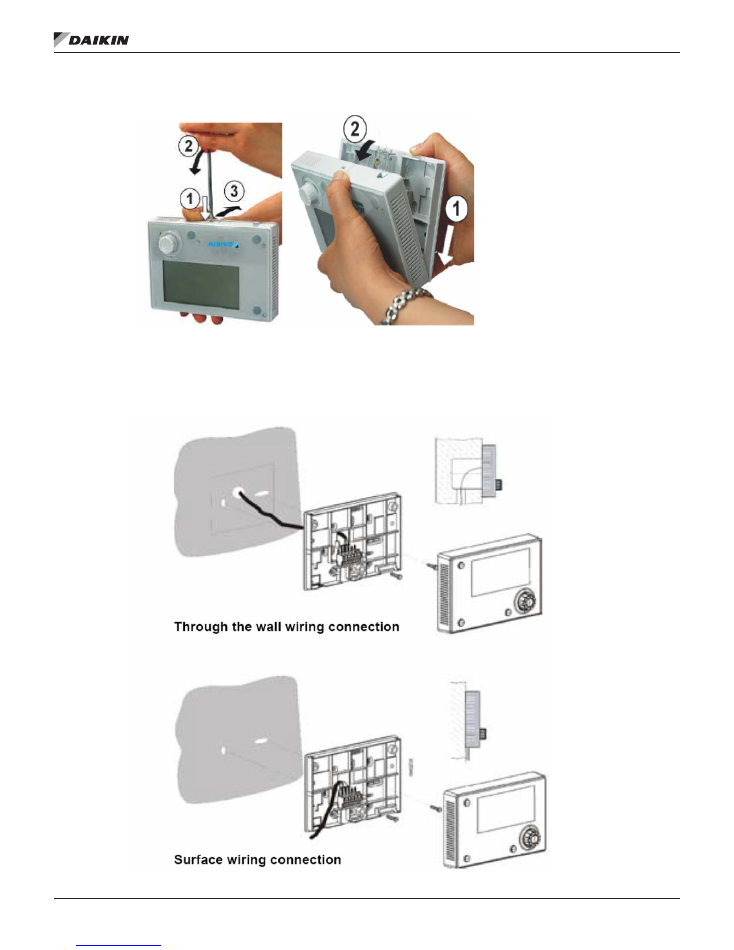
1. Remove plastic cover (
Figure 2)
.
2. Mount the remote user interface. The remote user
interface can be either panel mounted or wall mounted
as shown in
Figure 3
. See
Figure 4
and
Figure 5
for
terminal connections for each of the mounting locations.
IM 1005-3 • MICROTECH III REMOTE USER INTERFACE 6
www.DaikinApplied.com
Installation
Figure 2: Removing the Cover of remote user interface
Figure 3: Wall and Surface Wiring Connections
Installation
www.DaikinApplied.com
7
IM 1005-3 • MICROTECH III REMOTE USER INTERFACE
Wiring the Remote User Interface
Wiring the remote user interface to the MicroTech III unit
controller can be done in two different ways:
1. Daisy-chain connection to as many as eight units.
2. Direct connection to a single unit controller.
Connection and wiring instructions in each case are described
in the following section. See
Table 1
for wire sizing and
distance limitations.
NOTE:
Power is supplied by the MicroTech III unit
controller. If a separate 24V power supply
is desired, please contact either the Daikin
Applied Air Technical Response Center at 844-
521-3928 (techresponseaah@daikinapplied.
com) or the Chiller Technical Response Center
at 540-248-9239 (techresponse@daikinapplied.
com).
Table 1: Wiring Specifications
Daisy-Chain Connection
Establish a physical connection from the remote user
interface to the MicroTech III unit controller.
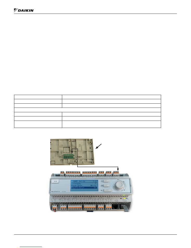
1. Connect a twisted pair wire to the CE + and CE – pins
of each unit controller and remote user interface (see
Figure 4
and
Figure 5
)
.
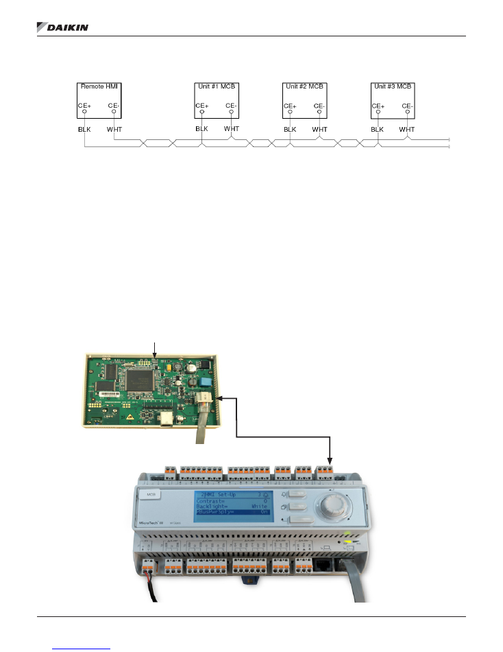
2. Daisy-chain up to eight MicroTech III unit controllers to
a single remote user interface. See
Figure 5
for wiring
details. Note the wire size and distance limitations
provided in
Table 1.
3. Cycle power to each MicroTech III unit controller once
the wiring of the remote user interface is complete.
NOTE:
Downloading and communication using the daisy-
chain connection may be slower than for the RJ45
(Ethernet) direct connection.
Figure 4: Interface Details for Daisy-Chain Connection
Bus connection
CE+, CE-, not interchangeable
Terminal
2-screw connector
Max. length
1000 ft (305 m)
Cable type
Wiring distance up to 500 ft
Twisted pair, shielded cable 16 AWG
Wiring distance between 500 - 1000 ft
Twisted pair, shielded cable 14 AWG
Wiring distance over 1000 ft
Not currently supported. Contact the appropriate Daikin Applied Technical Response
Center for assistance.
Remote User Interface Interior Bottom View
IM 1005-3 • MICROTECH III REMOTE USER INTERFACE 8
www.DaikinApplied.com
Installation
Figure 5: Daisy-Chain Connection Wiring Details
Direct Connection
The remote user interface can be wired directly to a single
MicroTech III unit controller over a standard RJ45 (Ethernet)
connection.
Procedure
1. Locate the connector location as shown in
Figure 6
2. Follow
Figure 6
for connection details. Note the distance
limitations provided.
3. Cycle power to the unit(s) once the wiring of the remote
user interface is complete.
NOTE:
Power is supplied by the unit controller. If a separate
24V power supply is desired, please contact either
the Daikin Applied Air Technical Response Center
at 844-521-3928 (techresponseaah@daikinapplied.
com) or the Chiller Technical Response Center at
540-248-9239 (techresponse@daikinapplied.com).
Figure 6: Interface Details for RJ45 Connector
Bus connection
Max length of shielded cable
Max. length of unshielded cable
Cable type
RJ45 interface
164 ft (50 m)
9.8 ft (3 m)
Standard Ethernet cable
Remote User Interface
Interior Top View
Operator's Guide
www.DaikinApplied.com
9
IM 1005-3 • MICROTECH III REMOTE USER INTERFACE
Operator's Guide
Using the Remote User Interface
Hardware Features
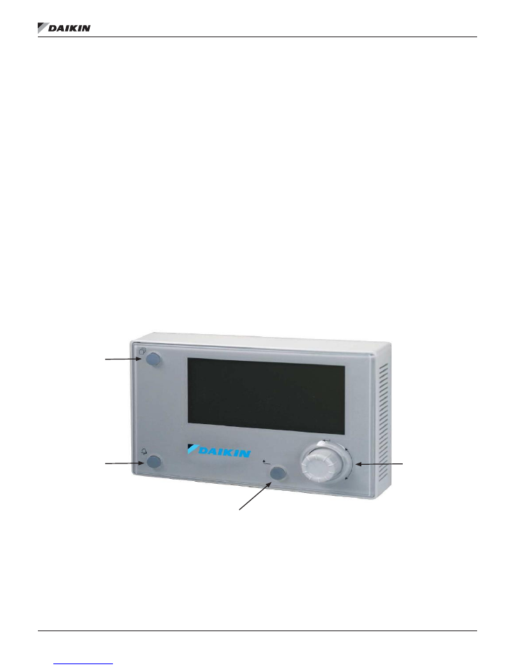
The remote user interface keypad/display consists of an 8-line
by 30 character display, a “push and roll” navigation wheel, and
three buttons: Alarm, Menu, and Back (
Figure 7
).
• Turn the navigation wheel clockwise (right) or
counterclockwise (left) to navigate between lines on a
screen and also to increase and decrease changeable
values when editing. Press down on the wheel to use it
as an Enter button.
• Press the Back button to display the previous page.
• Press the Home button to return to the main screen from
the current page.
• Press the Alarm button to view the Alarm Lists menu.
Keypad/Display Features
The first line on each page includes the page title and the line
number to which the cursor is currently “pointing.” The line
numbers are X/Y to indicate line number X of a total of Y lines
for that page. The left most position of the title line includes an
“up” arrow to indicate there are pages “above” the currently
displayed items, a “down” arrow to indicate there are pages
“below” the currently displayed items or an “up/down” arrow
to indicate there are pages “above and below” the currently
displayed page. Each line on a page can contain status-only
information or include changeable data fields. When a line
contains status-only information and the cursor is on that line,
all but the value field of that line is highlighted meaning the text
is white with a black box around it. When the line contains a
changeable value and the cursor is at that line, the entire line is
highlighted.
Each line on a page may also be defined as a “jump” line,
meaning pushing the navigation wheel will cause a “jump” to a
new page. An arrow is displayed to the far right of the line to
indicate it is a “jump” line and the entire line is highlighted when
the cursor is on that line.
NOTE:
Only menus and items that are applicable to the
specific unit configuration are displayed.
Figure 7: Remote User Interface Main Features
Home Button
Back Button
Navigation
Wheel
Alarm Button
IM 1005-3 • MICROTECH III REMOTE USER INTERFACE 10 www.DaikinApplied.com
Operator's Guide
Alarms
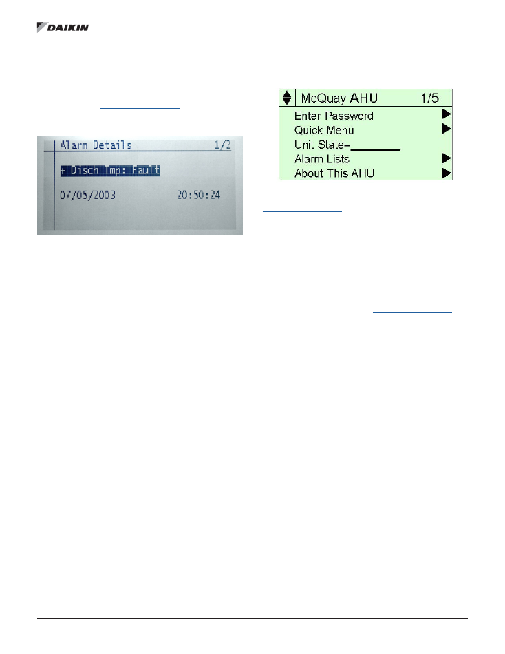
The Alarm Details Menu includes active alarm and alarm log
information. See
Figure 8
for an example of an active alarm.
Also refer to the appropriate MicroTech III unit controller
Operation Manual (
www.DaikinApplied.com
) for available alarm
options.
Figure 8: Alarm Details Menu
Passwords
U
nit controller menu functions have different levels of
accessibility. The ability to view and/or change settings
depends on the access level of the user and the password
entered. There are four levels of password access:
1. No password.
2. Level 2. The highest level of access. Without entering a
password, the user has access only to basic status menu
items. Entering the Level 2 password (6363) allows
similar access as Level 4 with the addition of the Unit
Configuration Menu.
3. Level 4. Entering the Level 4 password (2526) allows
similar access as Level 6 with the addition of the
Commission Unit Menu, Manual Control, and Service
Menu groups.
4. Level 6. Entering the Level 6 password (5321) allows
access to the Alarm Lists Menu, Quick Menu, and the
View/Set Unit Menus group.
NOTE:
Alarms can be acknowledged without entering a
password.
Accessing The Password Page
The main password page is displayed when the remote user
interface display (HMI) is first accessed.
1. Press the Home button.
2. Press the Back button multiple times, or if the keypad/
display has been idle longer than the Password Timeout
(default 10 minutes).
The main password page provides access to enter a
password, access the Quick Menu, view the current Unit
State, access the alarm lists or view information about the
unit (
Figure 9
).
Figure 9: Main Password Page
The MicroTech III unit controller Operation Manual
(
www.DaikinApplied.com
) provides additional information about
passwords, including how to use the Navigation and Edit Mode
settings to access and modify passwords.
Configuration
The following section describes how to set up the HMI so that
it can be used to display, configure, or change unit parameters.
Refer to the applicable MicroTech III unit controller Operation
Manual for a detailed description of chiller or rooftop sequence
of operation and keypad menu structure when configuring the
unit via the remote user interface (
www.DaikinApplied.com
).
NOTE:
To toggle between units, press the Home button for
five seconds to return to the main screen.
Customize User Preferences
1. Turn power on to the unit controller(s). Power to the
remote user interface is provided automatically from
the MicroTech III unit controller(s) through the RJ45
(Ethernet) direct connection.
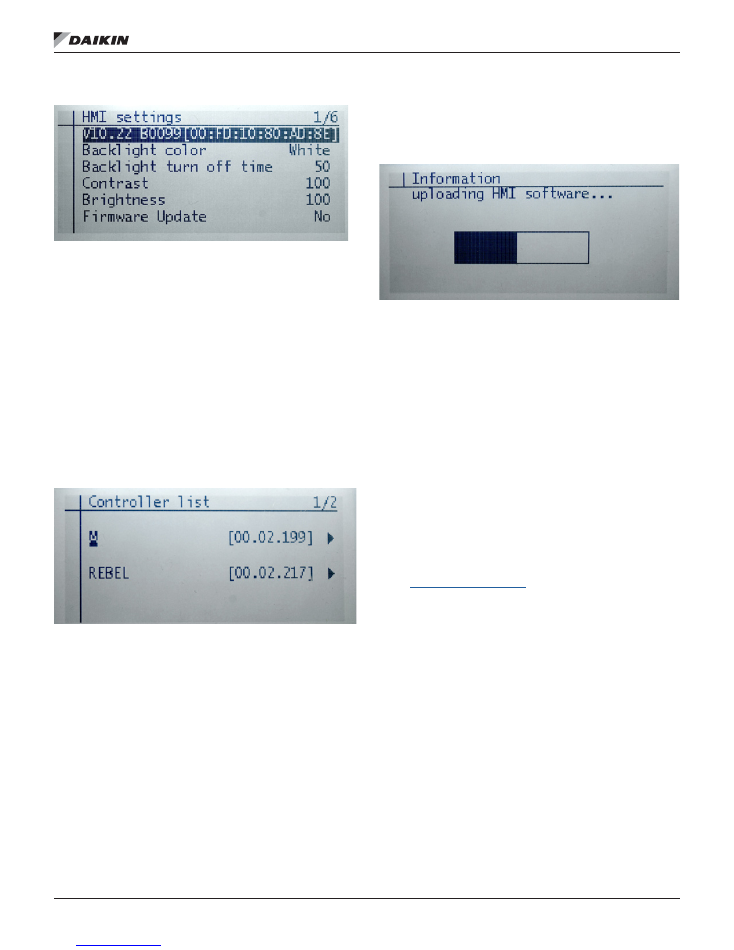
2. The main screen with HMI Settings and Controller List
appears (
Figure 10
).
Use the main menu screen to change options for backlight
color, backlight turn off time, contrast, and brightness.
NOTE:
The main screen can be accessed at any time by
pressing the Home button for five seconds.
3. Press the navigation wheel to select the HMI Settings
menu, if desired.
Operator's Guide
www.DaikinApplied.com 11
IM 1005-3 • MICROTECH III REMOTE USER INTERFACE
Figure 10: Main Screen HMI Settings
Synchronize with MicroTech III Unit
Controller
1. Press the navigation wheel to select the Controller List
screen (
Figure 11)
.
• The Controller List automatically updates each
time the remote user interface is powered up so
that information is synchronized from the main unit
controller.
• The Controller List screen displays the unit
controller(s) connected to the remote user interface.
This screen allows the user to select between units,
if more than one unit is connected to the remote user
interface
Figure 11: Controller List Details
NOTE:
A single unit appears on the screen as a selection
possibility if only one unit controller is connected to
the remote user interface.
2. Turn the navigation wheel clockwise and then press
down to select the desired unit.
• The Information screen appears as the remote user
interface performs a download sequence to import the
necessary information from the main unit controller. A
status bar appears on the Downloading the Objects
screen to indicate that the download is in process
(Figure 12
).
NOTE:
Refer to the Troubleshooting section if the remote
user interface appears to "freeze" during the initial
downloading sequence.
Figure 12: Information: Downloading Objects
3.
Once the first unit has been downloaded, select the next
unit controller, if applicable. The download process is
required for each unit controller connected to the remote
user interface.
4.
Press the Home button for five seconds to return to the
main screen.
NOTE:
The Downloading the Objects sequence generally
takes a minute or less when direct-connecting to a
single unit. However, the downloading sequence
takes longer when using the daisy-chain connection.
When the download sequence is complete, the Main
screen of the unit controller appears on the remote
user interface. At this point, the remote user interface
and unit controller are synchronized.
5. Access and adjust the same parameters that are
available via the unit controller keypad/display. Refer
to the applicable MicroTech III unit controller Operation
Manual for the keypad menu structure and detailed
description the unit controller sequence of operation
(
www.DaikinApplied.com
).

IM 1005-3 • MICROTECH III REMOTE USER INTERFACE 12 www.DaikinApplied.com
Operator's Guide
Firmware Upgrade Procedure
Follow these steps to update the remote user interface (HMI)
firmware (.bin) file.
NOTE:
The upgrade procedure requires the use of an SD
memory card no larger than 8GB with a FAT32 file
system format.
NOTE:
A field update is not possible on units with
v1.07 firmware. Contact the Daikin Applied Air
Technical Response Center at 844-521-3928
(techresponseaah@daikinapplied.com) or the Chiller
Technical Response Center at 540-248-9239
(techresponse@daikinapplied.com) for assistance.
Upgrading from VVS10 to a newer version
1. Upload
the firmware file, POL12289.bin, on the SD-Card
in the root directory with no other files.
2. Insert the SD Card into the MicroTech III unit controller.
The unit controller must be powered-up and running.
3. Connect the HMI DM to the unit controller.
4. Press the back button of the HMI DM until the “HMI
Setting and Local Connection” page appears.
a. Choose the HMI Setting. Scroll to the end of this
page and the “Firmware Update” option appears.
b. Push and roll to YES. Push the knob of the HMI
DM again.
5. The “Now Firmware Updating” message appears on the
user HMI display.
Do not remove power from the unit controller.
6.
After successful upgrade of the firmware, the HMI DM
goes back to the normal HMI page.
7.
Follow steps 1-4 to upgrade firmware for each HMI on a
daisy-chain network. Please be aware that each remote
user interface must use the same firmware version.
Troubleshooting
www.DaikinApplied.com 13
IM 1005-3 • MICROTECH III REMOTE USER INTERFACE
Troubleshooting
This section contains helpful information, frequently asked
questions, and other tips related to the remote user interface.
General Troubleshooting
During the initial download sequence, the keypad/display
appears to freeze up and a "Loading......Lost Connection"
message appears.
Solution
The remote user interface is stuck in the downloading
sequence due to incompatibility with v1.07 application
software. The remote user interface must be updated
to v10.22 or newer application software. Contact Daikin
Applied Air Technical Response at 844-521-3928 for further
instructions.
Problem
The remote user interface is experiencing a loss of
communication.
Solution
The site may have "dirty power" or electrical noise causing
loss of communication.
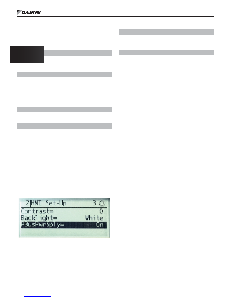
1. Access the Power Bus menu on the MicroTech III
unit controller by the following keypad menu path:
service menu/HMI setup/PBusPwrSply=ON (default).
See
Figure 13.
2. Set the default Power Bus supply.
a.
For the first and last units on the daisy-chain
trunk, leave the Power Bus supply at the default
of ON.
b. For all other units within the daisy chain trunk,
set the Power Bus supply to the OFF position.
Figure 13: Power Bus Menu
Problem
The remote user interface has been connected to the
MicroTech III unit controller but the display remains blank
after power-up.
Solution
Verify that the unit controller has power. Check wiring from
the unit controller to the remote user interface.
NOTE:
Inputs and outputs are polarity sensitive.
Frequently Asked Questions
1. Is a separate 24V power supply necessary for direct
connection?
→
No, power is provided by the MicroTech III unit
controller.
2. What type of cable is recommended for daisy-chain
connection?
→ Daikin Applied generally recommends using
twisted
pair, 16 AWG shielded cable up to 500 ft and 14 AWG
from 500 to 1000 ft. Contact the appropriate Technical
Response Center for applications requiring longer
distances.
How do I know if or when I need to upgrade the remote user
interface (HMI) firmware files?
→
If the remote user interface seems to freeze during
initial download process
→
If wiring has been confirmed (inputs and outputs are
polarity sensitive) and HMI is not responding
See
Firmware Upgrade Procedure
section for details.
What if I want to upgrade the MicroTech III unit controller
firmware?
→
Contact either the Daikin Applied Air
Technical Response Center at 844-521-3928
(techresponseaah@daikinapplied.com) or the Chiller
Technical Response Center at 540-248-9239
(techresponse@daikinapplied.com) for assistance.
Helpful Tips
Service technicians often find it convenient to have two
keypad/displays connected to a single unit controller. Using
a split-screen setup makes it possible to view multiple menu
items at the same time during start-up and also for diagnostic
purposes.
→
Simply hook up the first remote user interface with an
RJ45 direct connection, and then use a two-wire twisted
pair cable to connect to the second keypad/display.

IM 1005-3 (11/16)
©2016 Daikin Applied | (800) 432–1342 | www.DaikinApplied.com
Daikin Applied Training and Development
Now that you have made an investment in modern, efficient Daikin equipment, its care should be a high
priority. For training information on all Daikin HVAC products, please visit us at www.DaikinApplied.com
and click on Training, or call 540-248-9646 and ask for the Training Department.
Warranty
All Daikin equipment is sold pursuant to its standard terms and conditions of sale, including Limited
Product Warranty. Consult your local Daikin Applied representative for warranty details. To find your
local Daikin Applied representative, go to www.DaikinApplied.com.
Aftermarket Services
To find your local parts office, visit www.DaikinApplied.com or call 800-37PARTS (800-377-2787).
To find your local service office, visit www.DaikinApplied.com or call 800-432-1342.
This document contains the most current product information as of this printing. For the most up-to-date
product information, please go to www.DaikinApplied.com.
Products manufactured in an ISO Certified Facility.