Full Text Searchable PDF User Manual

Customer Documentation
DEV 2161 (1:4)
DEV 2162 (1:8)
DEV 2165 (1:16)
CFP Active L-Band Splitters
DEV Systemtechnik GmbH
Grüner Weg 4A
61169 Friedberg
GERMANY
Tel: +49 6031 6975 100
Fax: +49 6031 6975 114
support@dev-systemtechnik.com
www.dev-systemtechnik.com
Revision: 2017-12-13
DEV 91-0094-G

Customer Documentation DEV 2161, DEV 2162, DEV 2165
2
Copyright DEV Systemtechnik GmbH 2011-2017
TABLE OF CONTENTS
1
REVISION HISTORY ------------------------------------------------------------------------------ 3
2
INTRODUCTION ----------------------------------------------------------------------------------- 3
2.1
Warranty ---------------------------------------------------------------------------------------------- 3
2.2
Limitation of Warranty ----------------------------------------------------------------------------- 4
3
PRODUCT DESCRIPTION ---------------------------------------------------------------------- 4
3.1
Features and Options ------------------------------------------------------------------------------ 4
3.1.1
Splitter Units ----------------------------------------------------------------------------------------- 4
3.1.2
Additional Splitter Unit Options ------------------------------------------------------------------ 5
3.2
Product Drawings ----------------------------------------------------------------------------------- 5
3.2.1
DEV 2161 with 3 * Option 30 --------------------------------------------------------------------- 5
3.2.2
DEV 2162 with 3 * Option 31 --------------------------------------------------------------------- 6
3.2.3
DEV 2165 with Option 32 ------------------------------------------------------------------------- 6
4
INSTALLATION INSTRUCTIONS ------------------------------------------------------------- 7
4.1
Scope of Delivery ----------------------------------------------------------------------------------- 7
4.2
Installation of the Product ------------------------------------------------------------------------- 7
4.2.1
Mechanical Integration of the Product in a 19" Rack --------------------------------------- 7
4.2.2
Grounding and Power Connection -------------------------------------------------------------- 7
4.2.3
Connection of RF Signal Cables ---------------------------------------------------------------- 8
4.3
Maintenance of the Product ---------------------------------------------------------------------- 8
5
OPERATION OF THE PRODUCT ------------------------------------------------------------- 9
5.1
Operation via the Device Panel ----------------------------------------------------------------- 9
6
CONNECTORS ------------------------------------------------------------------------------------- 9
7
TECHNICAL DATA AND OPTIONS ----------------------------------------------------------- 9
8
SPARE PARTS ------------------------------------------------------------------------------------- 9
9
CONFORMANCE DECLARATIONS -------------------------------------------------------- 10
9.1
Certificate of Conformance --------------------------------------------------------------------- 10
9.2
Certificate of Conformance External Power Supply -------------------------------------- 12
9.3
EU Declaration of Conformity ------------------------------------------------------------------ 13
10
GLOSSARY ---------------------------------------------------------------------------------------- 14
11
NOTES ---------------------------------------------------------------------------------------------- 14
Customer Documentation DEV 2161, DEV 2162, DEV 2165
Copyright DEV Systemtechnik GmbH 2011-2017
3
1
REVISION HISTORY
Revision (Date)
Author Short Description
A (11-Nov-2011) WP
Initial version
B (01-Dec-2011) WP
Minor corrections
C (11-Jan-2012)
WP
Minor corrections
D (07-Aug-2012) WP
Integration of data sheet & minor corrections
E (09-Jul-2013)
WP
Integration of DEV 2165
F (11-Mar-2015)
WP
Documentation update
I (13-Dec-2017)
WP
Minor changes
2
INTRODUCTION
Thank you for purchasing a DEV 216x Active L-Band Splitter.
This customer documentation is intended to familiarize you with the
installation and operation of the device.
The DEV 216x is a series of active 1:4, 1:8, or 1:16 L-Band splitters, which
are especially developed for digital television and broadcasting applications
and which are designed for the use in ground stations and cable TV head
end stations to distribute high frequency signals to satellite receivers or
IRDs. All products of this series are delivered in a rack mountable 1 RU
chassis and are equipped with one to four splitter units.
The DEV 216x are members of the DEV Core Function Products (CFP) line.
Compared with DEV standard products the Core Function Products provide
the same superior RF transmission quality without certain features such as
integrated redundant power supplies, monitoring ports, RF sensing, and
other alarm functionality.
DEV Systemtechnik GmbH declares that this equipment meets all relevant
standards and rules. The product carries a CE mark.
Please read all instructions before installation or usage of the product!
2.1
WARRANTY
The product has a warranty against defects in material and workmanship for
a period of two years from the date of shipment. During the warranty period
DEV Systemtechnik will, at its option, either repair or replace the product if it
turns out to be defective.
For warranty, service, or repair, the product must be returned to DEV
Systemtechnik. The customer has to pay shipping charges to DEV
Systemtechnik and DEV Systemtechnik will pay shipping charges to return
the product to the customer. However, the customer is obliged to pay all
duties, all taxes, and all other additional costs arising from the shipment of
the product.
Customer Documentation DEV 2161, DEV 2162, DEV 2165
4
Copyright DEV Systemtechnik GmbH 2011-2017
2.2
LIMITATION OF WARRANTY
The preceding warranty does not apply to defects resulting from:
improper site preparation or site maintenance;
improper or inadequate interfacing of the product;
unauthorized modification or misuse of the product;
improper or inadequate maintenance of the product;
operation beyond the environmental conditions specified for the product.
Warning:
Disconnect the device from any external power line before opening of the
housing. In any case, the device is to be opened by especially trained
people, only.
3
PRODUCT DESCRIPTION
The DEV 2161, the DEV 2162, and the DEV 2165 are active splitters for the
frequency range 500…2300 MHz. By default, each product is equipped with
a single splitter unit with either 4 output ports (DEV 2161), or 8 output ports
(DEV 2162), or 16 output ports (DEV 2165). Optionally, the DEV 2165 can
be ordered with one additional splitter unit; and the DEV 2161 and the
DEV 2162 can be ordered with up to three additional splitter units.
The splitter units provide a switchable LNB power (or bias) supply; i.e. the
DC supply of LNBs or of inline amplifiers can be realized through the RF
input port of the splitter unit.
3.1
FEATURES AND OPTIONS
3.1.1
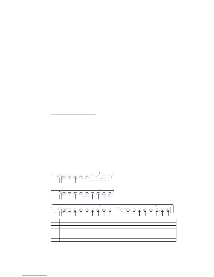
Splitter Units
B ia s
P w r
1 .C
1 .1
1 .2
1 .3
C
S P
B
1
2
3
1 .4
1 .5
1 .6
1 .7
1 .8
4
B ia s
P w r
1 .C
1 .1
1 .2
1 .3
C
S P
B
1
2
3
1 .4
1 .5
1 .6
1 .7
1 .8
4
5
6
7
8
B ia s
P w r
1 .C
1 .1
1 .2
1 .3
C
S P
B
1
2
3
1 .4
1 .5
1 .6
1 .7
1 .8
4
5
6
7
8
B ia s
P w r
2 .C
2 .1
2 .2
2 .3
2 .4
2 .5
2 .6
2 .7
2 .8
9
1 0
1 1
1 2
1 3
1 4
1 5
1 6
S
Splitter unit 1: Bias (or LNB power) push button
P
Splitter unit 1: Power LED
B
Splitter unit 1: Bias (or LNB power) LED
C
Splitter unit 1: Common input port; 75 Ohm, precision F(f)
1…4
Splitter unit 1: Output ports 1…4; 75 Ohm, precision F(f)
5…8
Splitter unit 1: Output ports 5…8; 75 Ohm, precision F(f) (DEV 2162 and DEV 2165 only)
9…16
Splitte
r unit 1: Output ports 9…16; 75 Ohm, precision F(f) (DEV 2165 only)
Customer Documentation DEV 2161, DEV 2162, DEV 2165
Copyright DEV Systemtechnik GmbH 2011-2017
5
A splitter unit consists of the common input port (
C
) and for the DEV 2161 of
four (
1…4
), for the DEV 2162 of eight (
1…8
), and for the DEV 2165 of
sixteen (
1…16
) output ports. A green power LED (
P
) is provided to indicate
that the splitter unit is supplied with power. A splitter unit is capable to deliver
LNB power (or bias) to the common input port. The bias (or LNB power)
push button (
S
) is used to turn on or off the LNB power (or bias) supply. A
ballpoint pen is recommended to operate the push button. If the LNB power
supply is turned off, the bias (or LNB power) LED (
B
) is off. If the LNB power
supply is turned on the LED is green.
3.1.2
Additional Splitter Unit Options
By default a DEV 216x is equipped with a single splitter unit.
By ordering the corresponding number of Option 30 for the DEV 2161 or of
Option 31 for the DEV 2162, the products are delivered with one to three
additional splitter units.
By ordering Option 32 for the DEV 2165, the product is delivered with a
second splitter unit.
3.2
PRODUCT DRAWINGS
The layout of the different products is almost identical. In the following, the
DEV 2161, the DEV 2162, and the DEV 2165 are shown in their maximum
configuration, i.e. with four (or two) splitter units installed. The appearance of
smaller configurations can be easily derived from these illustrations.
3.2.1
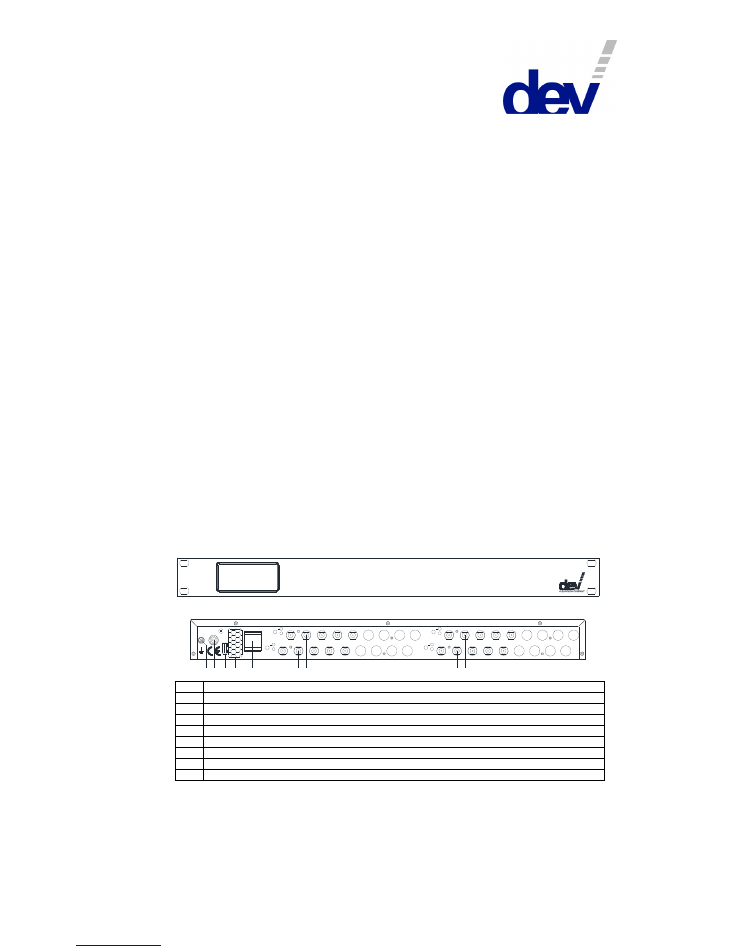
DEV 2161 with 3 * Option 30
Front View:
1 :4 A c tiv e L -B a n d S p litte r
D E V 2 1 6 1
Rear View:
B ia s
B ia s
B ia s
B ia s
P w r
P w r
P w r
P w r
1 .C
1 .1
1 .2
1 .3
1 .4
1 .5
1 .6
1 .7
1 .8
3 .C
3 .1
3 .2
3 .3
3 .4
3 .5
3 .6
3 .7
3 .8
2 .C
2 .1
2 .2
2 .3
2 .4
2 .5
2 .6
2 .7
2 .8
4 .C
4 .1
4 .2
4 .3
4 .4
4 .5
4 .6
4 .7
4 .8
G
C
L
E
1
P
3
2
4
E th e rn e t
+
1 8 V D C
-
5 0 V A
G
Grounding bolt
P
DC power inlet
C
Power cable support fixture
L
Serial number label
E
Fixture for Ethernet connector (not equipped for this type of product)
3
Splitter unit 3 (equipped only with 2 * (or more) Option 30)
1
Splitter unit 1 (always equipped)
4
Splitter unit 4 (equipped only with 3 * Option 30)
2
Splitter unit 2 (equipped only with 1 * (or more) Option 30)
Customer Documentation DEV 2161, DEV 2162, DEV 2165
6
Copyright DEV Systemtechnik GmbH 2011-2017
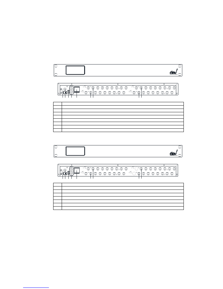
3.2.2
DEV 2162 with 3 * Option 31
Front View:
1 :8 A c tiv e L -B a n d S p litte r
D E V 2 1 6 2
Rear View:
B ia s
B ia s
B ia s
B ia s
P w r
P w r
P w r
P w r
1 .C
1 .1
1 .2
1 .3
1 .4
1 .5
1 .6
1 .7
1 .8
3 .C
3 .1
3 .2
3 .3
3 .4
3 .5
3 .6
3 .7
3 .8
2 .C
2 .1
2 .2
2 .3
2 .4
2 .5
2 .6
2 .7
2 .8
4 .C
4 .1
4 .2
4 .3
4 .4
4 .5
4 .6
4 .7
4 .8
G
C
L
E
1
P
3
2
4
E th e rn e t
+
1 8 V D C
-
5 0 V A
G
Grounding bolt
P
DC power inlet
C
Power cable support fixture
L
Serial number label
E
Fixture for Ethernet connector (not equipped for this type of product)
3
Splitter unit 3 (equipped only with 2 * (or more) Option 31)
1
Splitter unit 1 (always equipped)
4
Splitter unit 4 (equipped only with 3 * Option 31)
2
Splitter unit 2 (equipped only with 1 * (or more) Option 31)
3.2.3
DEV 2165 with Option 32
Front View:
1 :1 6 A c tiv e L -B a n d S p litte r
D E V 2 1 6 5
Rear View:
B ia s
B ia s
B ia s
B ia s
P w r
P w r
P w r
P w r
1 .C
1 .1
1 .2
1 .3
1 .4
1 .5
1 .6
1 .7
1 .8
3 .C
3 .1
3 .2
3 .3
3 .4
3 .5
3 .6
3 .7
3 .8
2 .C
2 .1
2 .2
2 .3
2 .4
2 .5
2 .6
2 .7
2 .8
4 .C
4 .1
4 .2
4 .3
4 .4
4 .5
4 .6
4 .7
4 .8
G
C
L
E
1
P
3
2
4
E th e rn e t
+
1 8 V D C
-
5 0 V A
P
DC power inlet
C
Power cable support fixture
L
Serial number label
E
Fixture for Ethernet connector (not equipped for this type of product)
3
Splitter unit 2, common port &
output ports 1…8 (equipped only with Option 32)
1
Splitter unit 1, common port &
output ports 1…8 (always equipped)
4
Sp
litter unit 2, output ports 9…16 (equipped only with Option 32)
2
Splitter unit 1, output ports 9…16 (always equipped)
Customer Documentation DEV 2161, DEV 2162, DEV 2165
Copyright DEV Systemtechnik GmbH 2011-2017
7
4
INSTALLATION INSTRUCTIONS
4.1
SCOPE OF DELIVERY
1 * DEV 2161 or DEV 2162 or DEV 2165
equipped with
additional splitter unit option(s)
as ordered
1 * DEV 79-0163 external power supply
1 * Customer documentation (this document)
4.2
INSTALLATION OF THE PRODUCT
4.2.1
Mechanical Integration of the Product in a 19" Rack
For the integration in a 19" rack, the rack slots must be prepared with rails
for the 1 RU chassis. After inserting the chassis in the rack, fix the chassis
with four screws to the rack at its rack mount flanges.
Warning:
It is absolutely not permitted to fix the chassis on the rack mount flanges,
only.
4.2.2
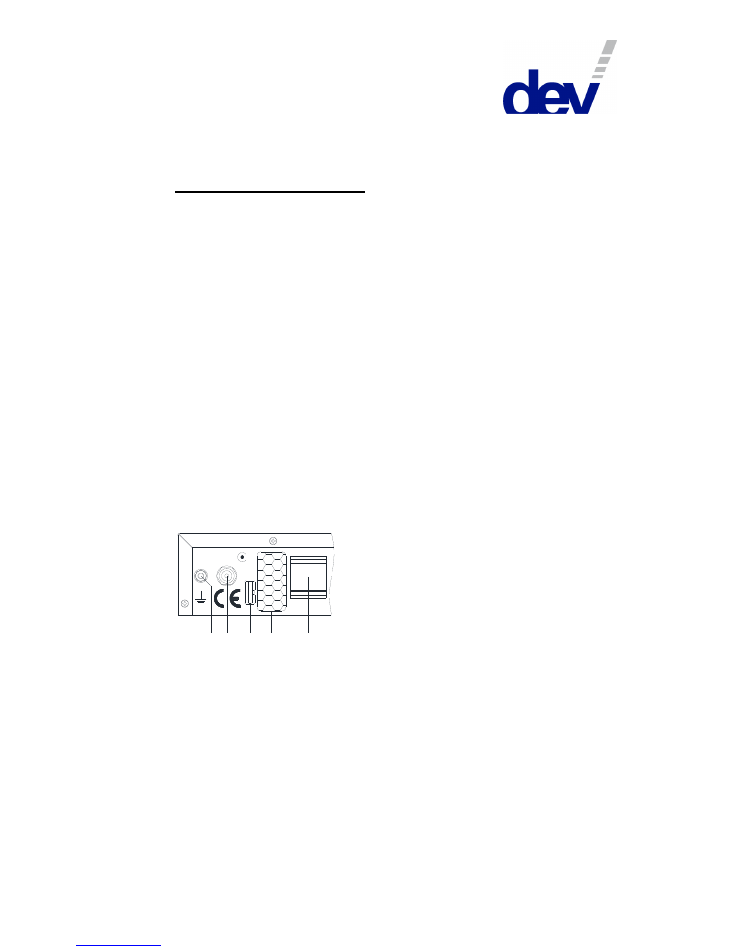
Grounding and Power Connection
The chassis needs to be connected to the 19" rack via a ground wire. The
grounding bolt (
G
) is located on the left at the rear side of the product:
G
C
L
E
P
E th e rn e t
+
1 8 V D C
-
5 0 V A
To connect the grounding cable, please take off the upper nut and the first
washer of the grounding bolt (
G
). Then connect the grounding cable, which
must have a ring tongue terminal matching for the M4 fastening bolt. The
washer and the nut have to be tightened again.
The external power supply delivered with the product has to be suitably
stowed away within the rack in a way, that it is firmly fixed, that the DC
output cable of the external power supply is in reach of the chassis, and that
the applied primary power cord is in reach of the external power supply and
of the available electrical outlet. First connect the DC output cable of the
external power supply to the DC power inlet (
P
) of the chassis; a cable
fixture (
C
) is provided for this cable to avoid unintentional disconnection.
Then connect a power cord on one side to the external power supply and on
the other side to the available electrical outlet.

Customer Documentation DEV 2161, DEV 2162, DEV 2165
8
Copyright DEV Systemtechnik GmbH 2011-2017
Note:
It is
highly recommended
to power up the device after the installation of
all RF signal cables (please refer to chapter 4.2.3).
4.2.3
Connection of RF Signal Cables
Please refer to chapter 3.1.1 for the functionality of the different RF signal
connectors on a splitter unit and to chapter 3.2 for the location and naming of
the single splitter units.
Apply strain relieves to the external RF cables which are to be connected in
a way that the connectors of the device are not stressed mechanically.
If the DEV 216x is powered up already and before the RF cables are to be
connected to the chassis, the LNB power (or bias) supply of all splitter units
is to be turned off! Otherwise, there is a risk that a high impulse current
degrades the RF performance of the corresponding input connector.
First, connect the RF input cable(s) (e.g. from the LNB) to the corresponding
input port(s); then connect the RF output cables (to the signal receivers) to
the output ports.
When connecting RF cables to the chassis, each connector is to be
tightened with a torque wrench. The torque applied to 75 Ohm F connectors
should not exceed 4.5 Nm (39.8 lbf-in).
Note:
For the products of this series, female precision F connectors are
applied. Make sure, that the applied connectors are male precision
F connectors (with thin inner conductor).
Each unused output port of a splitter unit has to be terminated with a
75 Ohm F load to achieve best amplitude frequency response.
Recommendation for the output wiring of a splitter unit:
Best signal quality is achieved by connecting the signal receivers
symmetrically to the outputs:
• 1…4 of each 1:4 splitter unit;
• 1…4 and 5…8 of each 1:8 splitter unit;
• 1…4, 5…8, 9…12, and 13…16 of each 1:16 splitter unit;
and
by connecting impedance matched loads to the unused ports.
If all cables are connected, the device can be powered up.
Now the LNB power (or bias) supply can be turned on for the splitter
units that are required to feed power to an LNB.
4.3
MAINTENANCE OF THE PRODUCT
The product is maintenance-free.
Cleaning of the surface of the chassis should be done carefully with a dry
lint-free cloth.
Customer Documentation DEV 2161, DEV 2162, DEV 2165
Copyright DEV Systemtechnik GmbH 2011-2017
9
5
OPERATION OF THE PRODUCT
After going through the installation steps as described above, the device is
ready to use.
5.1
OPERATION VIA THE DEVICE PANEL
Beside the bias (or LNB power) push button(s) (please refer to chapter
3.1.1), there is (are) no element(s) to be operated. The operating status of
each splitter unit and of each LNB power (or bias) supply is indicated via
LEDs, which were already described in chapter 3.1.1 as well.
6
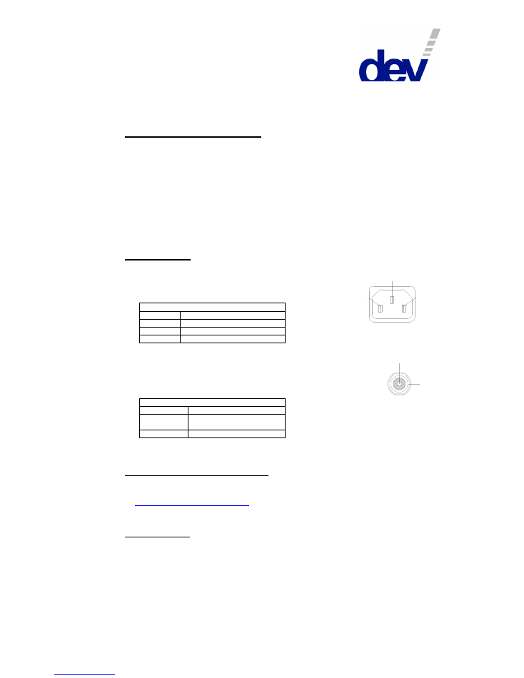
CONNECTORS
AC Power Plug (at the external power supply)
Connector:
IEC rubber connector (male) IEC 60320 C14
Connector screws:
none
AC Power Plug
Pin
Functionality
Pin 1
L (Live/Phase)
Pin 2
PE (Protective Earth)
Pin 3
N (Neutral)
DC Connector Plug (at the chassis)
Connector:
DC coaxial connector plug for connector with
OD (Outer Diameter): 5.5 mm (0.22") &
ID (Inner Diameter):
2.1 mm (0.08")
Connector screws:
none
DC Connector Plug
Pin
Functionality
Pin 1 (inner)
positive DC-Voltage
(+18 V nominal)
Pin 2 (outer)
GND
7
TECHNICAL DATA AND OPTIONS
The technical data and the options are stated in the data sheet; please refer
to
www.dev-systemtechnik.com
.
8
SPARE PARTS
External power supply; 18 V DC, 60 W
DEV 79-0163
1
2
3
1
2

Customer Documentation DEV 2161, DEV 2162, DEV 2165
10
Copyright DEV Systemtechnik GmbH 2011-2017
9
CONFORMANCE DECLARATIONS
This chapter comprises the Certificate of Conformance for the products
which are subject of this customer documentation (chapter 9.1), the
Certificate of Conformance for the external power supply (chapter 9.2), and
the EU Declaration of Conformity (chapter 9.3).
9.1
CERTIFICATE OF CONFORMANCE
Since DEV Systemtechnik develops and produces in Germany, the
Certificate of Conformance for each product or product series is to be issued
in German (as stated on the next page).
For the ease of comprehension, the harmonized standards that were taken
into consideration during development and production are listed here in
English:
DIN EN 50083-2:2016-03 Cable networks for television signals, sound signals and interactive services -
Part 2: Electromagnetic compatibility for equipment;
German version EN 50083-2:2012 + A1:2015
DIN EN 55022:2011-12
Information technology equipment - Radio disturbance characteristics -
Limits and methods of measurement
(CISPR 22:2008, modified); German version EN 55022:2010
DIN EN 55024:2016-05
Information technology equipment - Immunity characteristics -
Limits and methods of measurement
(CISPR 24:2010 + Cor.:2011 + A1:2015); German version EN 55024:2010 + A1:2015
DIN EN 61000-3-2:2015-03 Electromagnetic compatibility (EMC) - Part 3-2: Limits -
Limits for harmonic current emissions (equipment input current ≤ 16 A per phase)
(IEC 61000-3-2:2014); German version EN 61000-3-2:2014
DIN EN 61000-3-3:2014-03 Electromagnetic compatibility (EMC) - Part 3-3: Limits -
Limitation of voltage changes, voltage fluctuations, and flicker in public low-voltage
supply systems, for equipment with rated cur
rent ≤16 A per phase and not subject to
conditional connection
(IEC 61000-3-3:2013); German version EN 61000-3-3:2013
DIN EN 62368-1:2016-05 Audio/video, information and communication technology equipment -
Part 1: Safety requirements
(IEC 62368-1:2014, modified + Cor.:2015);
German version EN 62368-1:2014 + AC:2015

Customer Documentation DEV 2161, DEV 2162, DEV 2165
Copyright DEV Systemtechnik GmbH 2011-2017
11
Konformitätserklärung nach
EMV-Richtlinie (2014/30/EU)
Niederspannungsrichtlinie (2014/35/EU)
Der Hersteller:
DEV Systemtechnik GmbH
Grüner Weg 4A
61169 Friedberg
erklärt hiermit in alleiniger Verantwortung, dass nachfolgend bezeichnete Produkte in denen von uns in
Verkehr gebrachten Ausführungen:
Bezeichnung der Produkte: Aktive L-Band Splitter 1...4 * 1:4, 1...4 * 1:8 oder 1...2 * 1:16
Produktnummern
DEV 2161 (1:4), DEV 2162 (1:8), DEV 2165 (1:16)
Baujahr:
ab 2011
auf die sich diese Erklärung bezieht, mit den folgenden Normen übereinstimmen.
Bei der Konzipierung und beim Bau der Geräte wurden die folgenden harmonisierten Normen
berücksichtigt:
DIN EN 50083-2:2016-03 Kabelnetze für Fernsehsignale, Tonsignale und interaktive Dienste -
Teil 2: Elektromagnetische Verträglichkeit von Geräten;
Deutsche Fassung EN 50083-2:2012 + A1:2015
DIN EN 55022:2011-12
Einrichtungen der Informationstechnik - Funkstöreigenschaften -
Grenzwerte und Messverfahren
(CISPR 22:2008, modifiziert); Deutsche Fassung EN 55022:2010
DIN EN 55024:2016-05
Einrichtungen der Informationstechnik - Störfestigkeitseigenschaften -
Grenzwerte und Prüfverfahren
(CISPR 24:2010 + Cor.:2011 + A1:2015); Deutsche Fassung EN 55024:2010 + A1:2015
DIN EN 61000-3-2:2015-03 Elektromagnetische Verträglichkeit (EMV) - Teil 3-2: Grenzwerte -
Grenzwerte für Oberschwingungsströme (Geräte-Einga
ngsstrom ≤16 A je Leiter)
(IEC 61000-3-2:2014); Deutsche Fassung EN 61000-3-2:2014
DIN EN 61000-3-3:2014-03 Elektromagnetische Verträglichkeit (EMV) - Teil 3-3: Grenzwerte -
Begrenzung von Spannungsänderungen, Spannungsschwankungen und Flicker in
öffentlichen Niederspannungs-Versorgungsnetzen für Geräte mit einem
Bemessungsstrom ≤16 A je Leiter, die keiner Sonderanschlussbedingung unterliegen
(IEC 61000-3-3:2013); Deutsche Fassung EN 61000-3-3:2013
DIN EN 62368-1:2016-05 Einrichtungen für Audio/Video-, Informations- und Kommunikationstechnik -
Teil 1: Sicherheitsanforderungen
(IEC 62368-1:2014, modifiziert + Cor.:2015);
Deutsche Fassung EN 62368-1:2014 + AC:2015
DEV Systemtechnik GmbH
_____________________________
Friedberg, 13.12.2017
Jörg Schmidt
Managing Director
Customer Documentation DEV 2161, DEV 2162, DEV 2165
12
Copyright DEV Systemtechnik GmbH 2011-2017
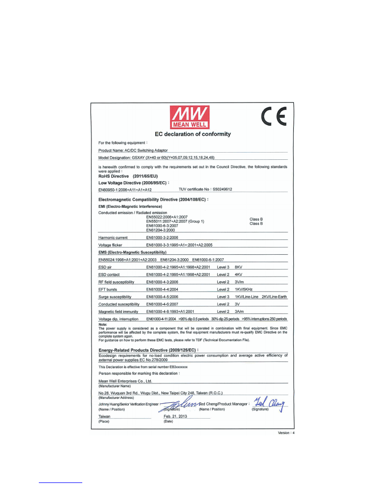
9.2
CERTIFICATE OF CONFORMANCE EXTERNAL POWER SUPPLY

Customer Documentation DEV 2161, DEV 2162, DEV 2165
Copyright DEV Systemtechnik GmbH 2011-2017
13
9.3
EU DECLARATION OF CONFORMITY
As original manufacturer of Electrical & Electronic Equipment (EEE)
DEV Systemtechnik GmbH
Grüner Weg 4A
61169 Friedberg
GERMANY
declares under sole responsibility that the
Products:
DEV 2161
CFP 1:4 Active Splitter; 500…2300 MHz; 75 Ohm, F (f)
DEV 2162 CFP 1:8
Active Splitter; 500…2300 MHz; 75 Ohm, F (f)
DEV 2165 CFP 1:16
Active Splitter; 500…2300 MHz; 75 Ohm, F (f)
Options:
• 30 (for DEV 2161);
• 31 (for DEV 2162);
• 32 (for DEV 2165);
• and future options
to which this declaration refers to, is in conformity with Directive 2011/65/EU of the European Parliament
and of the Council of 8-Jun-2011 on the restriction of the use of certain hazardous substances in
electrical and electronic equipment (RoHS).
Signed for and on behalf of DEV Systemtechnik GmbH
Name:
Jörg Schmidt
Position:
Managing Director
Place and date of issue: Friedberg, 13-Dec-2017
Signature:

Customer Documentation DEV 2161, DEV 2162, DEV 2165
14
Copyright DEV Systemtechnik GmbH 2011-2017
10
GLOSSARY
AC
A
lternating
C
urrent
CFP
C
ore
F
unction
P
roducts
(product line within the DEV Systemtechnik product portfolio)
DC
D
irect
C
urrent
IRD
I
ntegrated
R
eceiver
D
ecoder; also simply referred to as "receiver"
LED
L
ight
E
mitting
D
iode
LNB
L
ow
N
oise
B
lock Converter
RF
R
adio
F
requency
RU
R
ack
U
nit: Units of vertical height. 1 RU = 1 ¾" = 44.45 mm
Sometimes simply referred to as "U" (Unit).
11
NOTES