Full Text Searchable PDF User Manual
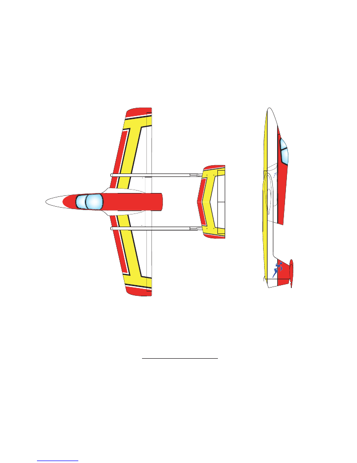
Wingspan........ 75.5" (1920mm)
Length............. 73" (1850 mm)
Weight 14lb.( 6.35kg ) Dry.
Radio....... 5 to 7 Channels.
Designer Alan Cardash
Boomerang RC Jets,
LLC
.
Website www.boomerang
-RC-
jets.com
SPRINT
Boomerang
Aerobatic Sport / Trainer Jet for 12 to 22 Lb. Thrust turbines
Almost ready to fly. Speed range from 18 to 150 MPH.
SAFETY PRECAUTIONS
The SPRINT turbine model is designed for experienced modellers. This model is not
recommended for beginners to R/C flying and should not be attempted by those with insuf-
ficient building and flying experience. This manual is for guidance only. If you are unsure of
any model building techniques, seek help from an experienced model builder or contact
Boomerang
RC
Jets
LLC
.
for assistance. Jet models are dangerous if construction
is carelessly or incorrectly carried out. As the building assembly of this kit is out of our
control after point of sale, no liability is accepted by
Boomerang RC Jets LLC
.
for any
accident or loss, however caused. Purchase of this kit implies acceptance of these condi-
tions by the purchaser. To decline these terms, return the unused kit to your supplier for full
refund.
S
P
R
I
N
T
Boomerang
S
P
R
I
N
T
3
1
2
3
Centre Wing
2.6 x12mm Screws
1
2 x 200mm
Pushrod
1
Clevis
4
Self-adhesive
Self-adhesive
Self-adhesive
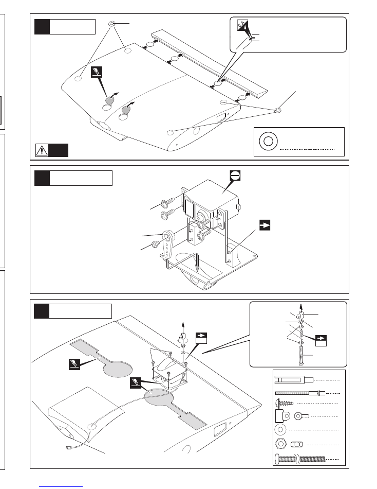
Open the holes for
access to the wing
fixing bolts then apply
the self adhesive
rings.
Warning!
Cut away covering film.
Not supplied
Be sure to glue securely.
This is Vital for safe flying!
Apply thin Cyano glue to both
sides of hinges to ensure good
penetration.
Typical Servo Mount
Flap Servo Installation
14
29
30
Check Hatch fit
Canopy fix
1
Aluminum tube
Aluminum tube
Drill to suit your servos.
Not supplied
Not supplied
2.6 x12mm
TP Screw
Cut away covering film.
For Main Landing Gear
3mm
3mm
3mm Nut
3mm Washer
4
2.6 x12mm TP Screw
1
1
2
1
3 x 50mm Bolt
3mm Nut
3mm Washer
3mm Horn
3mm Horn
3 x 50mm Bolt
31
Decals
84
9
U.
S.
AI
R
FO
RC
E
SP
RI
NT
12
84
9
U.S
.A
IR
FO
RC
E
SP
RIN
T
128
49
84
9
849
USAF
USAF
USAF
S
P
R
I
N
T
Boo
m
e
r
a
ng
S
P
R
I
N
T
S
P
R
I
N
T
Boo
m
e
r
a
ng
S
P
R
I
N
T
Boomerang S
P
R
I
N
T
S
P
R
I
N
T
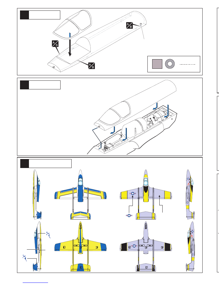
Trim the hatch latch and if necessary adjust
the front peg to achieve a good sliding fit.
A small smear of grease
on the slots & alloy
buttons
will help the hatch to slide easily
into place.
4
4
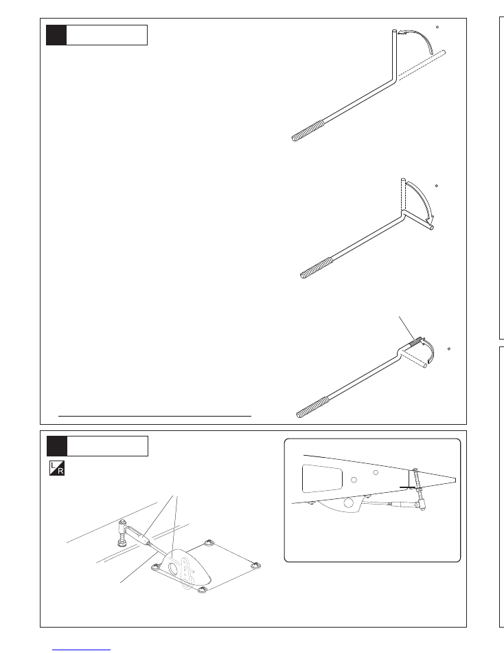
To Make the Pushrods to the length required;-
(1)
Make a 90 degree bend in the wire at the length required
to meet the output hole in the servo arm with the servo
centred.
(2) Now make a second bend off at 90 degrees to the first one,
left or right, in the wire at approx. 3mm away from the first
bend.
(3) Straighten the wire by gripping each side of the “Z” bend
with pliers and slowly turning until the ends are in line. Now
cut off the excess wire. The output hole in the servo arm
may have to be drilled out to accommodate the “Z” bend
wire passing through it. Adjustment of the pushrod length
is carried out by adjusting the clevis along the threaded
part of the pushrod.
An extra pushrod is supplied to allow for possible error.
13
28
27
Fuel Tank etc
Pushrods
Cut
90
90
90
5
Flap control
Note hinge position and the control horn
Rearward to allow maximum 90 degree
downward movement for the flap.
Assemble left and right sides
the same way.
2mm.pushrods and clevises (Supplied)
Supplied
Fix with silicon sealant.
Air Intakes
Cut away covering film.
Cut away covering film.
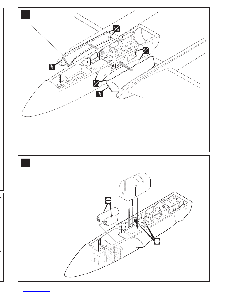
A custom Sullivan 3.7 litre fuel tank made for this kit is
available from your Boomerang Jets dealer. Otherwise it
is possible to fit any container from 2 litres up by
modifying the fuselage formers as required. Ensure that
the tank is well secured by using long cable tie wraps
through the formers. Do not simply depend on the tank
bay floor for this. A full tank of fuel weighs anything up to
8 Lbs (4 Kilos) and in a negative G manoeuvre can exert
considerable upward pull.
Clean up the front opening of the air intakes as necessary. After carefully
stripping away covering from the small cutouts in the upper fuselage use
the air intakes as a guide to how much covering to remove from each side
of the fuselage, opening up the airflow openings each side and leaving a
bare wood gluing surface just a few mm. smaller than the intakes all round
ready to fix the intakes using thick CA glue. In addition the “FOD” protective
mesh supplied can be added to the inside openings of all the intakes to
prevent debris being sucked in by the turbine while running at high RPM.
As with all turbine models, it is important to prevent this if you are flying
from dusty or gritty surfaces.
5
7
8
6
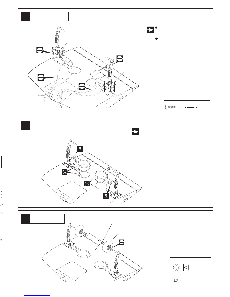
Main Landing Gear
Main Landing Gear
2
2
5.2mm Collar
3 x 4mm grub Screw
12
26
24
25
6
2 x 8mm TP Screw
Noseleg
Noseleg Cover Plate
2.6 x12mm
TP Screw
16
2.6 x12mm TP Screw
2.6 x12mm
TP Screw
Requires some modification
on main gear cover.
For Retractable landing gear
.
Not Supplied.
Not Supplied.
Not Supplied.
Main Landing Gear
Cut off shaded portion.
The main leg retracts should
be fitted about ½” inboard of
the centre wing tip.
2 x 8mm TP Screw
Trim the cover plate as required.
Fuselage/Wing joining
4mm
4mm Washer
4 x 50mm Bolt
NO:1007
2x8mm Screw
2
2
4 x 50mm Bolt
4mm Washer
2
NO:1007
2x8mm Screw
6
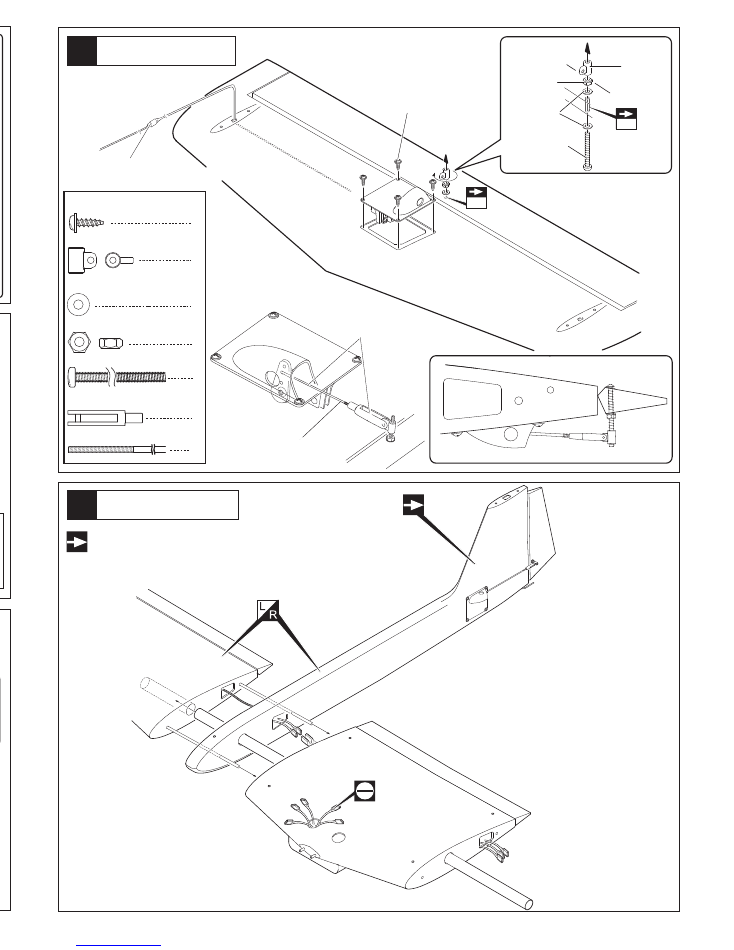
Cut away the covering from the slots on top of the centre wing. Place
the fuselage wing seat tabs into the slots. Mark the wingtop covering
along each side where the fuselage sits on the wing. Remove the
fuselage and carefully cut through the covering without damaging the
balsa abd strip off the the film between the marks you have made.
Now strip the covering carefully from the underside edge only of the
fuselage wing seat. Before finally gluing the wing to the fuselage, drill
and inset the alloy dowels to the front of the wing,. These will slip into
the parts No. 1007 supplied which should be epoxied to the former
using these dowels to adjust their position. Drill a 4mm hole through
the wing and plywood plate in the fuselage near the trailing edge and
fit the blind nuts on the topside of the ply. When satisfied with the fit,
epoxy the fuselage to the wing and tighten the bolts moderately with
washers to give a strong wing fix. The wing is not designed to be
removable.
Cut off shaded portion.
55mm
5.2mm Collar
3 x 4mm
grub Screw
For Retractable landing gear
Not Supplied.
NOTE;
Do not fix plastic wheel wells until the
servo wires and air lines are in place.
Level off the surface around the retract units.
The height of the landing gear should be
approximately as follows;
Noseleg 11cms. and mains 12cms.
from underside surfaces to the wheel axles.
Not Supplied.
6
10
11
9
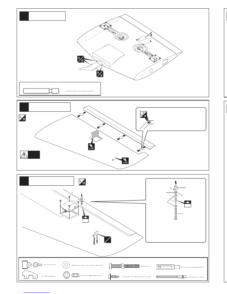
Aileron Servo installation
Outer wing panel
Centre Wing
When cutting away the film,for
the servo mount leave a gener-
ous overhang to allow for the
strong shrinkage of the Profilm
(Orocover) when you finally iron
it back in place.
A
B
Assemble left and right sides
the same way.
Assemble left and right sides
the same way.
Be sure to apply instant type CA glue to
both sides of each hinges.
(low viscosity type)
Cut away covering film.
Warning!
2.6 x12mm TP Screw
Be sure to glue securely.
This is Vital for safe flying!
11
23
22
For Retractable landing gear.
Noseleg Servo
Noseleg Mounting
“Trim the Cover Plate to clear the leg.”
8
2.6 x12mm TP Screw
2
2 x 100mm
Pushrod
2
Clevis
The nose leg length adjusted to give a
degree or two negative incidence or slightly
nose down attitude when Intro is standing on
a level surface. This will be easily overcome
on take off by the elevator authority and will
also help to eliminate bounce on landing.
2
2
4
2
3 x 50mm Bolt
3mm Nut
3mm Washer
3mm Horn
3mm
3mm Nut
3mm Washer
3mm Horn
3 x 50mm Bolt
3mm
Apply thin cyano top and bottom and
immediately tighten the 3mm. nut to
prevent the 3mm. bolt rotating.
2
Aluminium joiner
6 x 40mm
Aluminium joiners
6 x 40mm
Not Supplied.
Not Supplied.
2mm
Not Supplied.
4
2.6 x12mm TP Screw
2.6 x12mm TP Screw
2
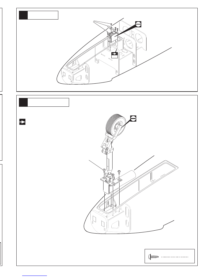
Cut away part of the former at the
rear of the rails to allow the retract
unit steering arms to drop cleanly aft
of the retract mounting rails.
7
14
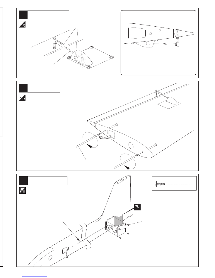
Rudder Servo installation
Cut away covering film.
8
2.6 x12mm TP Screw
2.6 x12mm TP Screw
Assemble left and right sides
the same way.
500mm. servo extension wires to rudder
servos in both booms. Alos 700mm.
extension wires to Elevator Servo in
Left hand boom only .(not supplied)
10
21
20
In order to save weight at the tail end, you
can use “Midi” servos for the rudders. If you
do this make up 6mm (1/4”) liteply plates to
raise the smaller servos and reduce the
standard spacing of the servo mountings
supplied. Remember to allow for the shrink-
age of the covering when cutting away for
the servo mounts.
Tail Assembly
3 x 20mm Bolt
4
3 x 20mm Bolt
3 x 20mm Bolt
Decrease size of top
exit hole after wires
are through to prevent
the connector falling
inside the fin.
Self-adhesive
4
Self-adhesive
13
12
Aileron Servo installation
Completed
Outer wing
Assemble left and right sides
the same way.
Assemble left and right sides
the same way.
2.5mm Hex Wrench
Lock
3 x 10mm Bolt
4
3x10mm Bolt
3x10mm Bolt
Wing Top
Wing Locking
3mm.(or 4/40)pushrods
and clevises (Supplied)
Supplied
8x285mm
Screw in the 8 X 285 mm alloy rods.
8
16
17
15
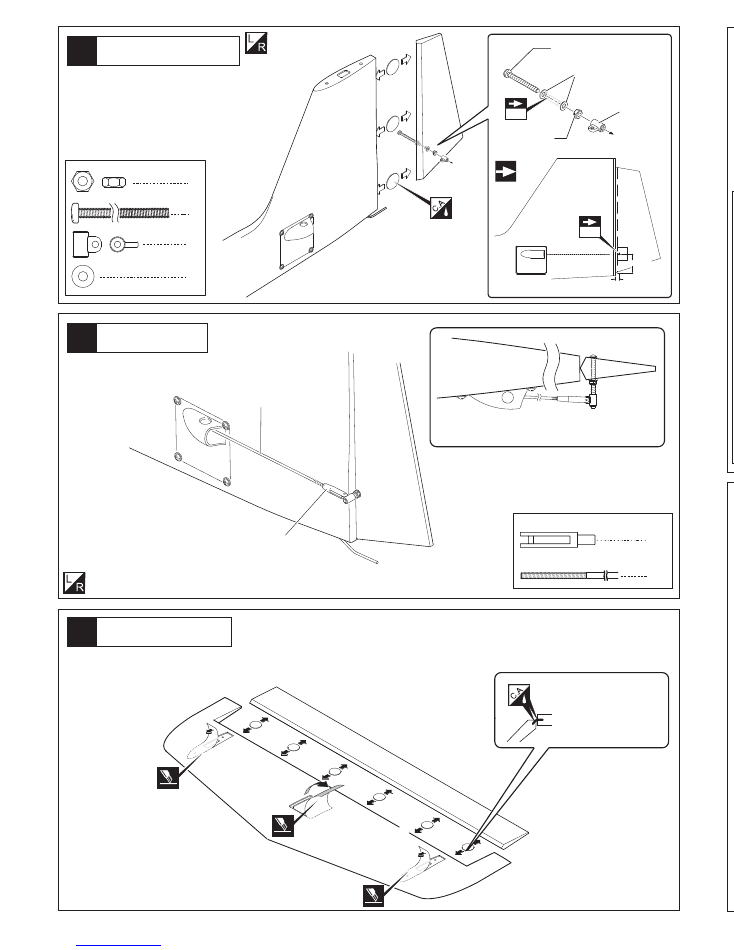
Rudder installation
Assemble left and right sides
the same way
Assemble left and right sides
the same way.
Rudder installation
9
19
18
Elevator Servo installation
Assemble left and right sides
the same way.
Right sides
Final Assembly
The tailskids are designed to swivel freely.
2
2 x 200mm Pushrod
2
Clevis
2
2
4
2
3 x 50mm Bolt
3mm Nut
3mm Washer
3mm Horn
3mm
3mm Nut
3mm Washer
3mm Horn
3 x 50mm Bolt
3mm
14mm
54mm
Completed
Apply thin Cyano to the 3 x 50mm.
Bolt after pushing it through the control
surface, and immediately tighten the nut
to prevent rotation.
3mm. or 4/40 pushrod and
clevises (supplied).
supplied
Completed
4
2.6 x12mm TP Screw
1
1
2
1
3 x 50mm Bolt
3mm Nut
3mm Washer
3mm Horn
3mm
3mm Nut
3mm Washer
3mm Horn
3 x 50mm Bolt
2.6 x12mm TP
Screw
3mm
Apply thin Cyano to the 3 x 50mm.
Bolt after pushing it through the control
surface, and immediately tighten the nut
to prevent rotation.
Supplied
3mm.(or 4/40)pushrods
and clevises (Supplied)
1
2 x 200mm Pushrod
1
Clevis
Tailplane/Stab
Be sure to apply instant
type CA glue to both
sides of each hinges.
(low viscosity type)
Cut away covering film.
Extension lead
1.5 metres (along booms to elevators)
Right boom shown.
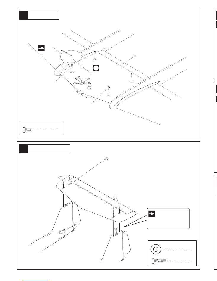
Adjusting the Carbon Fibre Spars.
If it is necessary to adjust the fit of the C/F spars within the wings,
apply the Heatshrink supplied to the spars as shown.
The spars should be “snug”,but not tight.
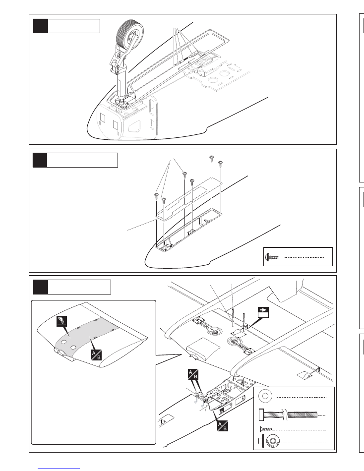
Cut away the plywood
stays across the
fuselage and the hatch
where they are marked.
These are for packing
only, not structural to
the airframe.
Lightly iron the covering through a cloth with a warm iron before cutting away
covering film for the servo mount. Leave 3mm overhang all round the servo mounts
as per the wings.
7
14
Rudder Servo installation
Cut away covering film.
8
2.6 x12mm TP Screw
2.6 x12mm TP Screw
Assemble left and right sides
the same way.
500mm. servo extension wires to rudder
servos in both booms. Alos 700mm.
extension wires to Elevator Servo in
Left hand boom only .(not supplied)
10
21
20
In order to save weight at the tail end, you
can use “Midi” servos for the rudders. If you
do this make up 6mm (1/4”) liteply plates to
raise the smaller servos and reduce the
standard spacing of the servo mountings
supplied. Remember to allow for the shrink-
age of the covering when cutting away for
the servo mounts.
Tail Assembly
3 x 20mm Bolt
4
3 x 20mm Bolt
3 x 20mm Bolt
Decrease size of top
exit hole after wires
are through to prevent
the connector falling
inside the fin.
Self-adhesive
4
Self-adhesive
13
12
Aileron Servo installation
Completed
Outer wing
Assemble left and right sides
the same way.
Assemble left and right sides
the same way.
2.5mm Hex Wrench
Lock
3 x 10mm Bolt
4
3x10mm Bolt
3x10mm Bolt
Wing Top
Wing Locking
3mm.(or 4/40)pushrods
and clevises (Supplied)
Supplied
8x285mm
Screw in the 8 X 285 mm alloy rods.
6
10
11
9
Aileron Servo installation
Outer wing panel
Centre Wing
When cutting away the film,for
the servo mount leave a gener-
ous overhang to allow for the
strong shrinkage of the Profilm
(Orocover) when you finally iron
it back in place.
A
B
Assemble left and right sides
the same way.
Assemble left and right sides
the same way.
Be sure to apply instant type CA glue to
both sides of each hinges.
(low viscosity type)
Cut away covering film.
Warning!
2.6 x12mm TP Screw
Be sure to glue securely.
This is Vital for safe flying!
11
23
22
For Retractable landing gear.
Noseleg Servo
Noseleg Mounting
“Trim the Cover Plate to clear the leg.”
8
2.6 x12mm TP Screw
2
2 x 100mm
Pushrod
2
Clevis
The nose leg length adjusted to give a
degree or two negative incidence or slightly
nose down attitude when Intro is standing on
a level surface. This will be easily overcome
on take off by the elevator authority and will
also help to eliminate bounce on landing.
2
2
4
2
3 x 50mm Bolt
3mm Nut
3mm Washer
3mm Horn
3mm
3mm Nut
3mm Washer
3mm Horn
3 x 50mm Bolt
3mm
Apply thin cyano top and bottom and
immediately tighten the 3mm. nut to
prevent the 3mm. bolt rotating.
2
Aluminium joiner
6 x 40mm
Aluminium joiners
6 x 40mm
Not Supplied.
Not Supplied.
2mm
Not Supplied.
4
2.6 x12mm TP Screw
2.6 x12mm TP Screw
2
Cut away part of the former at the
rear of the rails to allow the retract
unit steering arms to drop cleanly aft
of the retract mounting rails.
5
7
8
6
Main Landing Gear
Main Landing Gear
2
2
5.2mm Collar
3 x 4mm grub Screw
12
26
24
25
6
2 x 8mm TP Screw
Noseleg
Noseleg Cover Plate
2.6 x12mm
TP Screw
16
2.6 x12mm TP Screw
2.6 x12mm
TP Screw
Requires some modification
on main gear cover.
For Retractable landing gear
.
Not Supplied.
Not Supplied.
Not Supplied.
Main Landing Gear
Cut off shaded portion.
The main leg retracts should
be fitted about ½” inboard of
the centre wing tip.
2 x 8mm TP Screw
Trim the cover plate as required.
Fuselage/Wing joining
4mm
4mm Washer
4 x 50mm Bolt
NO:1007
2x8mm Screw
2
2
4 x 50mm Bolt
4mm Washer
2
NO:1007
2x8mm Screw
6
Cut away the covering from the slots on top of the centre wing. Place
the fuselage wing seat tabs into the slots. Mark the wingtop covering
along each side where the fuselage sits on the wing. Remove the
fuselage and carefully cut through the covering without damaging the
balsa abd strip off the the film between the marks you have made.
Now strip the covering carefully from the underside edge only of the
fuselage wing seat. Before finally gluing the wing to the fuselage, drill
and inset the alloy dowels to the front of the wing,. These will slip into
the parts No. 1007 supplied which should be epoxied to the former
using these dowels to adjust their position. Drill a 4mm hole through
the wing and plywood plate in the fuselage near the trailing edge and
fit the blind nuts on the topside of the ply. When satisfied with the fit,
epoxy the fuselage to the wing and tighten the bolts moderately with
washers to give a strong wing fix. The wing is not designed to be
removable.
Cut off shaded portion.
55mm
5.2mm Collar
3 x 4mm
grub Screw
For Retractable landing gear
Not Supplied.
NOTE;
Do not fix plastic wheel wells until the
servo wires and air lines are in place.
Level off the surface around the retract units.
The height of the landing gear should be
approximately as follows;
Noseleg 11cms. and mains 12cms.
from underside surfaces to the wheel axles.
Not Supplied.
4
4
To Make the Pushrods to the length required;-
(1)
Make a 90 degree bend in the wire at the length required
to meet the output hole in the servo arm with the servo
centred.
(2) Now make a second bend off at 90 degrees to the first one,
left or right, in the wire at approx. 3mm away from the first
bend.
(3) Straighten the wire by gripping each side of the “Z” bend
with pliers and slowly turning until the ends are in line. Now
cut off the excess wire. The output hole in the servo arm
may have to be drilled out to accommodate the “Z” bend
wire passing through it. Adjustment of the pushrod length
is carried out by adjusting the clevis along the threaded
part of the pushrod.
An extra pushrod is supplied to allow for possible error.
13
28
27
Fuel Tank etc
Pushrods
Cut
90
90
90
5
Flap control
Note hinge position and the control horn
Rearward to allow maximum 90 degree
downward movement for the flap.
Assemble left and right sides
the same way.
2mm.pushrods and clevises (Supplied)
Supplied
Air Intakes
Cut away covering film.
Cut away covering film.
A custom Sullivan 3.7 litre fuel tank made for this kit
is available from your Boomerang Jets dealer.
Otherwise it is possible to fit any container from 2
litres up by modifying the fuselage formers as
required. Ensure that the tank is well secured by
using long cable tie wraps through the formers. Do
not simply depend on the tank bay floor for this. A
full tank of fuel weighs anything up to 8 Lbs (4 Kilos)
and in a negative G manoeuvre can exert consider-
able upward pull.
Clean up the front opening of the air intakes as necessary. After carefully
stripping away covering film from the small cutouts in the supper fuselage use the
air intakes as a guide to how much covering to remove from each side of the
fuselage, opening up the airflow openings each side and leaving a bare wood
gluing surface just a few mm. smaller than the intakes all around ready to fix the
intakes using think CA glue. The air intake is glued to the fuselage only, not to the
wing.
3
1
2
3
Centre Wing
2.6 x12mm Screws
1
2 x 200mm
Pushrod
1
Clevis
4
Self-adhesive
Self-adhesive
Self-adhesive
Open the holes for
access to the wing
fixing bolts then apply
the self adhesive
rings.
Warning!
Cut away covering film.
Not supplied
Be sure to glue securely.
This is Vital for safe flying!
Apply thin Cyano glue to both
sides of hinges to ensure good
penetration.
Typical Servo Mount
Flap Servo Installation
14
29
30
Check Hatch fit
Canopy fix
1
Aluminum tube
Aluminum tube
Drill to suit your servos.
Not supplied
Not supplied
2.6 x12mm
TP Screw
Cut away covering film.
For Main Landing Gear
3mm
3mm
3mm Nut
3mm Washer
4
2.6 x12mm TP Screw
1
1
2
1
3 x 50mm Bolt
3mm Nut
3mm Washer
3mm Horn
3mm Horn
3 x 50mm Bolt
31
Decals
84
9
U.
S.
AI
R
FO
RC
E
SP
RI
NT
1
28
49
U.S
.A
IR
FO
RC
E
SP
RIN
T 1
284
9
84
9
849
USAF
USAF
USAF
S
P
R
I
N
T
Boo
m
e
r
a
ng
S
P
R
I
N
T
S
P
R
I
N
T
Boo
m
e
r
a
ng
S
P
R
I
N
T
Boomerang
S
P
R
I
N
T
S
P
R
I
N
T
Trim the hatch latch and if necessary adjust
the front peg to achieve a good sliding fit.
A small smear of grease
on the slots & alloy
buttons
will help the hatch to slide easily
into place.

Wingspan........ 75.5" (1920mm)
Length............. 73" (1850 mm)
Weight 14lb.( 6.35kg ) Dry.
Radio....... 5 to 7 Channels.
Designer Alan Cardash
E-Mail;-boomerangjets@aol.com
Website www.boomerangjets.com
TRIMMING SET UP & FLYING NOTES
Boomerang SPRINT is not tricky or difficult to set up.
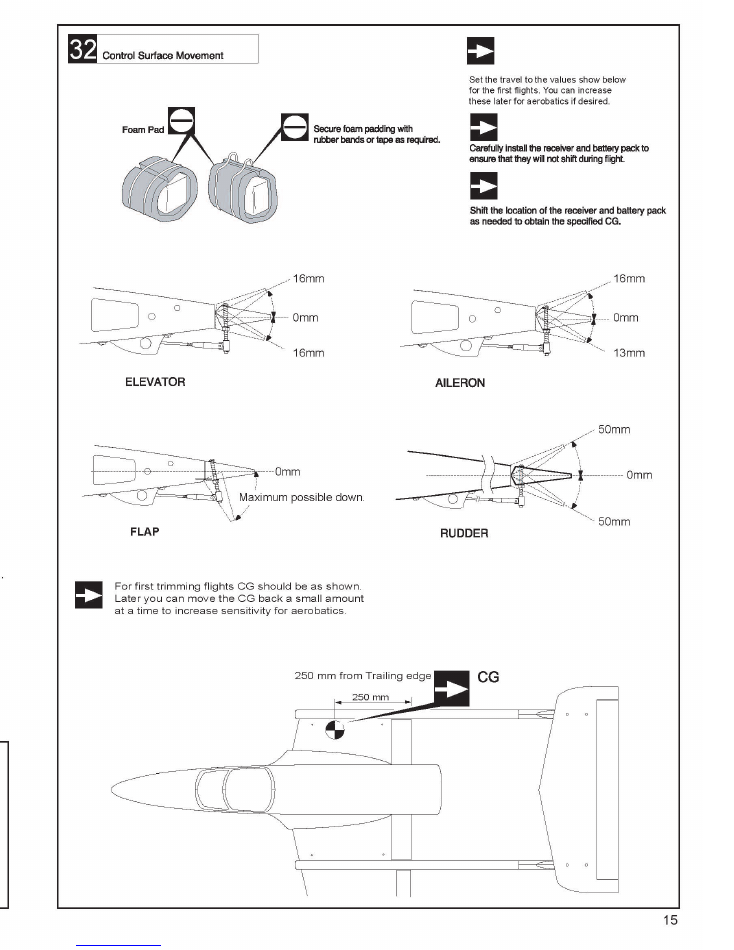
Set the Centre of Gravity no less than 10” (255 mm.) forward of the
Trailing Edge for the first flights.
Start with 5/8” up and ½” down Aileron (16 & 13 mm.). Elevators 5/8”
(16mm) up and down. Adjust later to your personal preferences.
The flap is very effective in slowing the glide speed. Set it up to drop
as far as possible, to act as an airbrake. If you can add crow braking
starting from half flap to full flap, to raise both ailerons about 15 to
20 degrees, the slow flight and the descent rate on the approach is
remarkable, with full control at very low airspeeds using slightly
open throttle allowing a high angle of attack with virtually no risk of
dropping a wing.
Mix in 10% down elevator with the flap movement to prevent the
nose rising as it is applied. If you have advanced mixing, this should
return to zero from half flap to full down flap.
SPRINT is capable of any aerobatics you care to try, including spins
both upright and inverted, snaps, tumbles, rolling circles and loops,
knife edge and very slow flight.
The fuel tank custom made by Sullivan for us will give up to 15
minutes of flying time. It can, of course, be only partially filled for
shorter flights if you prefer.
You should enjoy some good flying fun with the Sprint, just about
the most stress free jet flying you can get! Feel free to
provide
your feedback and comments to us
on our website:
www.
Boomerang-RC-Jets.com
SPRINT
Boomerang
Aerobatic Sport / Trainer Jet for 12 to 22 Lb. Thrust turbines
Almost ready to fly. Speed range from 18 to 150 MPH.
SAFETY PRECAUTIONS
The SPRINT turbine model is designed for experienced modellers. This model is not
recommended for beginners to R/C flying and should not be attempted by those with insuf-
ficient building and flying experience. This manual is for guidance only. If you are unsure of
any model building techniques, seek help from an experienced model builder or contact
Boomerang Jets Ltd for assistance. Jet models are dangerous if construction is carelessly
or incorrectly carried out. As the building assembly of this kit is out of our control after point
of sale, no liability is accepted by Boomerang Jets Ltd or Boomerang Jets USA Llc for any
accident or loss, however caused. Purchase of this kit implies acceptance of these condi-
tions by the purchaser. To decline these terms, return the unused kit to your supplier for full
refund.
S
P
R
I
N
T
Boomerang
S
P
R
I
N
T

IMPORTANT WARNING.
READ THROUGH BEFORE ASSEMBLING OR FLYING YOUR KIT.
Just as in any full size aircraft, any RIC model aircraft can be made to fail, be it a wing folding or a fuse
lage breaking under too high a load. Model RIC aircraft have a maximum safe G limit. Because you are
not in the plane it is difficult to judge the G during flight, and it is very easy to exceed the limits of the
aircraft. This is particularly important if you install a turbine larger or more powerful than the power band
specified for that particular kit. This negates any airframe warranty straight away.
All our designs are thoroughly test flown before the kit is released for sale. Turbine powered RIC model
aircraft are not manufactured to withstand unlimited G forces. When flying your Boomerang Jet, be
aware of the high loads which can be in excess of the airframes capability to handle. Respect the
airframe as you would when flying a full size aircraft. Fit a turbine only up to the specified power.
Understand that if you perfonn a snap roll, wall, blender, knife edge loop or any similar manoeuvre, or
pull hard on the elevator, particularly at high speed, you can over stress the airframe by up to15 G or
more. At 15 G, the 27 lbs (12.2 Kilo) model effectively weighs over400 lbs (184 kilo), and though it may
be for only a few seconds, the strain on the airframe is huge. Your model may survive those hard
manoeuvres a few times, but eventually the cumulative damage will tell and airframe break up can
occur.
It is common practice for any manufacturer not to replace an airframe which breaks in the air or upon
landing. Manufacturers may replace airframes when they have noticed many incidences of the same
failure and it is detennined that there was a design fault or repeated manufacturing error. If you break
an airframe, and you are the only one to do so, then it is highly unlikely to be the fault of the manufac
turer. Fly safely, and avoid full throttle operation other than at low airspeeds.
RIC model jets are not toys! If misused, they can cause serious bodily hann and property damage. Fly
only in open areas, and AMA (Academy of Model Aeronautics) or BMFA (British Model Flying Associa
tion) or your country's approved flying sites. Follow all manufacturer instructions included with your
plane, radio, servo's, batteries and engine. Each kit is guaranteed to be free from defects in both mate
rial and workmanship at the date of purchase. Warranty does not cover any component assembled by
the customer. All parts of high stress must be inspected and reinforced if necessary by a competent
builder.
Some parts should be examined, and if necessary, glued again. High stress areas such as firewalls,
motor mounts, wing mounts, landing gear mounts, etc., are areas of high concern. Seek help if neces
sary.
In no case shall Boomerang RC Jets, LLC. warranty cover any product which is not manufactured by
Boomerang RC Jets, LLC. The liability to the manufacturer cannot exceed the original cost of the
purchased item.
Further, Boomerang RC Jets, LLC. reserves the right to change or modify this warranty without notice.
In that Boomerang RC Jets, LLC. has no control over the assembly or materials used by the builder of
the model during final assembly, no liability shall be assumed nor accepted for any damage resulting
from the use of the final user-assembled product. By using the user assembled product, the user
accepts all resulting liability. The kits manufacturers have provided you with a top quality, thoroughly
tested kit and instructions, but ultimately the quality and flying ability of your finished model depends on
how you build it. Therefore, we cannot in any way guarantee the performance of your completed
model, and no representations are expressed or implied as to the performance or safety of your com
pleted model. It is the use�s responsibility to inspect each component for airworthiness.