Full Text Searchable PDF User Manual
4s2
Variable Temperature Thermal Sealer Service Manual
Version: B
23 September 2010

4s2 Variable Temperature Thermal Sealer Service Manual
4titude Ltd, The North Barn, Surrey Hills Business Park, Damphurst Lane, Wotton, Dorking, Surrey, RH5 6QT, UK
Tel: +44 (0) 1306 884885 Fax: +44 (0) 1306 884886 info@4ti.co.uk www.4ti.co.uk
Page 1
4s2 VARIABLE TEMPERATURE THERMAL SEALER
SERVICE MANUAL
This manual is intended to be used as a guide to maintaining the HT121TS thermal sealer. It is valid for
the units with S/N higher than 42256.
The information contained in this document is subject to change without notice.
This document is for information only, manufacturer accepts no liability for errors contained herein or for
incidental or consequential damages with the furnishing, performance, or use of this material.
If not otherwise specified, each reference to names or belongings is purely casual and has the purpose
to illustrate the product here described. Contents of this publication may not be reproduced in any form
or by any means (including electronic storage and retrieval or translation into a foreign language)
without prior agreement and written consent from the copyright owner.
All rights are reserved.

4s2 Variable Temperature Thermal Sealer Service Manual
4titude Ltd, The North Barn, Surrey Hills Business Park, Damphurst Lane, Wotton, Dorking, Surrey, RH5 6QT, UK
Tel: +44 (0) 1306 884885 Fax: +44 (0) 1306 884886 info@4ti.co.uk www.4ti.co.uk
Page 2
PAGE INDEX
Page #
1
TROUBLE SHOOTING GUIDE
3
1.1 Trouble Shooting Guide
3
1.2 Terminology and Abbreviation
3
2
INTRODUCTION
4
2.1 Warnings
4
2.2 General Trouble Shooting Tips
4
3
OPERATION
5
3.1 High Handler Sensor Adjustment
5
3.2 Low Handler Sensor Adjustment
6
3.3 Drawer Sensor Adjustment
8
3.4 Front-to-Back Adjustment
9
3.5 Left-to-Right Adjustment
12
4
SPARE PARTS & ACCESSORIES
13

4s2 Variable Temperature Thermal Sealer Service Manual
4titude Ltd, The North Barn, Surrey Hills Business Park, Damphurst Lane, Wotton, Dorking, Surrey, RH5 6QT, UK
Tel: +44 (0) 1306 884885 Fax: +44 (0) 1306 884886 info@4ti.co.uk www.4ti.co.uk
Page 3
1 TROUBLE SHOOTING GUIDE
1.1 Trouble Shooting Guide
Below are the possible faults encountered, and their most probable solutions. Some of
these are hypothetical faults, as they have not been encountered.
Fault
Cause
Solution
Difficulty
Comments
No power
Blown fuse
Replace fuse
*
See User Manual
Unit switched on
but motors do not
move
Incorrect voltage set
Change voltage from
220V to 110V
*
See User Manual
Unit continues to
heat and gives
temperature error,
“ER6”
Old firmware version
installed
Update firmware to
latest version
***
See IG-007:
Instructions for
upgrading
software
Unit switched on
but gives
temperature error,
“ER6”
Unit is too cold
Allow unit to reach
ambient temperature
and retry
*
Motor can’t reach
“home” position.
“ER1” or “ER4”
appear or
countdown starts
without
compressing the
plate
High handler sensor
remains active in
“home” position
Readjust the High
Handler Sensor bar
*****
See 3.1
Unit gives
overcurrent error
after compression
“ER5”
High handler sensor
isn’t active when the
unit is compressing
Readjust the High
Handler Sensor bar
*****
See 3.1
Unit gives low
handler sensor
error, “ER8”
Low handler sensor
i
sn’t active when the
motor starts running
Readjust the Low
Handler Sensor bar
****
See 3.2
1.2 Terminology and Abbreviation
Difficulty Rating:
*
Easy (can be performed by end-user)
**
Moderate (experienced user)
***
Average (trained technician required)
****
Difficult
*****
Very difficult (operate unit under voltage)

4s2 Variable Temperature Thermal Sealer Service Manual
4titude Ltd, The North Barn, Surrey Hills Business Park, Damphurst Lane, Wotton, Dorking, Surrey, RH5 6QT, UK
Tel: +44 (0) 1306 884885 Fax: +44 (0) 1306 884886 info@4ti.co.uk www.4ti.co.uk
Page 4
2 INTRODUCTION
2.1 Warnings
This manual is intended for trained technicians only
All the procedures, if not differently specified, must be performed with the unit
disconnected from the mains voltage (main power).
If the procedures request to operate with the power on, do NOT touch the PCB or any
internal parts that might have a voltage.
Handle the unit with care.
If it is necessary to use tools not provided with the 4s2 or to work on faults or parts of the
unit not included within this Service Manual, please contact your supplier.
2.2 General Trouble Shooting Tips
If a fault occurs and you are unsure about the problem please contact your supplier giving
the serial number of the unit and as much information about the fault as possible.
4s2 Variable Temperature Thermal Sealer Service Manual
4titude Ltd, The North Barn, Surrey Hills Business Park, Damphurst Lane, Wotton, Dorking, Surrey, RH5 6QT, UK
Tel: +44 (0) 1306 884885 Fax: +44 (0) 1306 884886 info@4ti.co.uk www.4ti.co.uk
Page 5
3 OPERATION
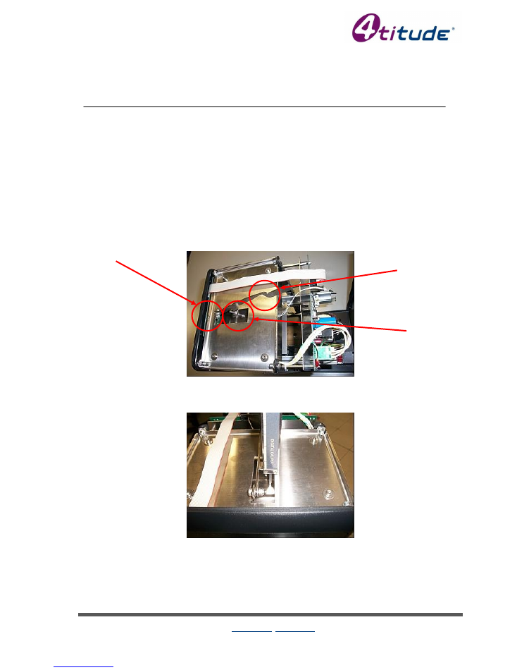
3.1 High Handler Sensor Adjustment
1. Remove the cover
2. Check the high handler bar sensor can move freely. If not, unscrew the M4 screw that fixes
the bar slightly (see “1”, Figure 1).
3. Check the bar is aligned to the sensor OPT3, on the top of the electronic board. If not,
gently bend the bar to realign it.
4. Switch on the unit, push down the bar and check the LED LD3, on the top of the electronic
board remains off. If not, gently bend the bar upwards slig
htly (see “2”, Figure 1).
5. During a compression cycle (at ambient temperature) check with a calliper the distance from
the heater carter and the top plate that supports the heater and bar is 15 +/- 0.5 mm (see
Figure 2). If not, alter the distance using t
he M3 screw and lock it with the M3 nut (see “3”,
Figure 1)
Figure 1 - Sensor Bar Adjustment
Figure 2 - Compression Check
1
2
3
4s2 Variable Temperature Thermal Sealer Service Manual
4titude Ltd, The North Barn, Surrey Hills Business Park, Damphurst Lane, Wotton, Dorking, Surrey, RH5 6QT, UK
Tel: +44 (0) 1306 884885 Fax: +44 (0) 1306 884886 info@4ti.co.uk www.4ti.co.uk
Page 6
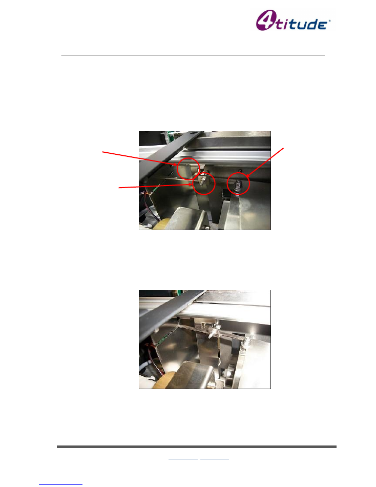
3.2 Low Handler Sensor Adjustment
1. Remove the cover.
2. Check the high handler bar sensor can move freely. If not, unscrew the M4 screw that fixes
the bar slightly (see “1”, Figure 3).
3. Check the bar is aligned to the sensor OPT1, on the bottom of the electronic board. If not,
gently bend the bar to realign it.
4. Check the bar hook doesn't touch the drawer, and that the distance from the hook and
the bottom bar of the drawer is less than 1mm (see “2”, Figure 3). If not, alter the
distance using the M3 screw and lock it with the M3 nut (see “3”, Figure 3).
Figure 3 - Lower Handler Adjustment
5. Disconnect the motor cable from the electronic board (2 poles connector J3)
6. Close the drawer completely and manually lift up the platen (rotate the motor manually)
until the hook completely blocks the drawer. Check the drawer can move by
approximately 1 mm by pushing it (see Figure 4). If not, unscrew the two screws that fix
the L-bar to the drawer, and re-position it. Re-tighten the two screws (see Figure 5). If
necessary, gently bend the L-bar.
Figure 4 - Drawer Locked
7. Reconnect the motor cable.
1
2
3

4s2 Variable Temperature Thermal Sealer Service Manual
4titude Ltd, The North Barn, Surrey Hills Business Park, Damphurst Lane, Wotton, Dorking, Surrey, RH5 6QT, UK
Tel: +44 (0) 1306 884885 Fax: +44 (0) 1306 884886 info@4ti.co.uk www.4ti.co.uk
Page 7
Figure 5
– L-Bar Positioning

4s2 Variable Temperature Thermal Sealer Service Manual
4titude Ltd, The North Barn, Surrey Hills Business Park, Damphurst Lane, Wotton, Dorking, Surrey, RH5 6QT, UK
Tel: +44 (0) 1306 884885 Fax: +44 (0) 1306 884886 info@4ti.co.uk www.4ti.co.uk
Page 8
3.3 Drawer Sensor Adjustment
1. Remove the cover.
2. Disconnect the motor cable from the electronic board (2 poles connector J3).
3. Close the drawer completely and manually lift up the platen (rotate the motor manually)
until the hook blocks completely the drawer.
4. Switch on the unit, pull the drawer and verify that the LED LD2 (on the bottom of the
electronic board) remains off (regardless of unit errors). If not, switch off the unit,
unscrew the screw on the drawer sensor bar and re-position it (see Figure 6). Re-tighten
the screw.
Figure 6 - Drawer Sensor Adjustment
5. Switch off the unit.
6. Reconnect the motor cable.
4s2 Variable Temperature Thermal Sealer Service Manual
4titude Ltd, The North Barn, Surrey Hills Business Park, Damphurst Lane, Wotton, Dorking, Surrey, RH5 6QT, UK
Tel: +44 (0) 1306 884885 Fax: +44 (0) 1306 884886 info@4ti.co.uk www.4ti.co.uk
Page 9
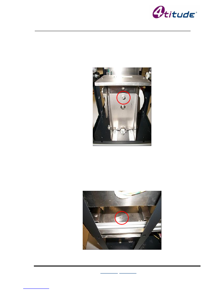
3.4 Front-to-Back Adjustment
3.4.1 Units up to Serial Number 42330
1. Remove the cover.
2.
Locate the M4 screw underneath platen that receives the PCR / microplate (see Figure
7). If the front of the PCR / microplate is under-sealed, tighten the screw. If the back
of the PCR / microplate is under-sealed, loosen the screw.
Figure 7 - Front-to-Back Screw Adjustment
3. It may also be necessary to adjust the drawer:
3.1. Disconnect the motor cable.
3.2. Close the drawer completely and manually lift up the platen (rotate the motor
manually).
3.3. Check the pins on the lift are aligned to the adaptor plate hole (see Figure 8). If not,
adjust the drawer front panel by unscrewing the four M3 screws (see Figure 9), then
execute
“Drawer Sensor Adjustment” (see page 8).
Figure 8 - Adapter Aligned
4s2 Variable Temperature Thermal Sealer Service Manual
4titude Ltd, The North Barn, Surrey Hills Business Park, Damphurst Lane, Wotton, Dorking, Surrey, RH5 6QT, UK
Tel: +44 (0) 1306 884885 Fax: +44 (0) 1306 884886 info@4ti.co.uk www.4ti.co.uk
Page 10
Figure 9 - Front Panel Adjustment
3.4. Reconnect the motor cable.
3.4.2 Units from Serial number 42343
1. Remove the cover
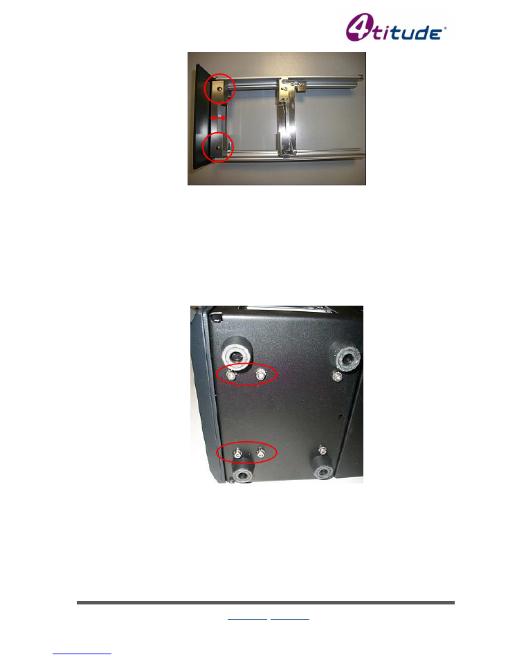
2. Unscrew the 4 screws that fix the lift (Figure 10).
Figure 10 - Lift Screws
4s2 Variable Temperature Thermal Sealer Service Manual
4titude Ltd, The North Barn, Surrey Hills Business Park, Damphurst Lane, Wotton, Dorking, Surrey, RH5 6QT, UK
Tel: +44 (0) 1306 884885 Fax: +44 (0) 1306 884886 info@4ti.co.uk www.4ti.co.uk
Page 11
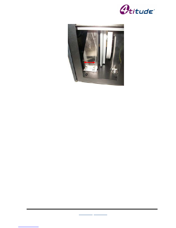
3. Move the lift towards front or back to centralize to the heating block (Figure 11)
Figure 11 - Adjusting the lift's position
4. Screw the 4 screw that fix the lift.
5. Execute the operations described in point 3 of the previous paragraph (3.4.1).
4s2 Variable Temperature Thermal Sealer Service Manual
4titude Ltd, The North Barn, Surrey Hills Business Park, Damphurst Lane, Wotton, Dorking, Surrey, RH5 6QT, UK
Tel: +44 (0) 1306 884885 Fax: +44 (0) 1306 884886 info@4ti.co.uk www.4ti.co.uk
Page 12
3.5 Left-to-Right Adjustment
1. Remove the cover.
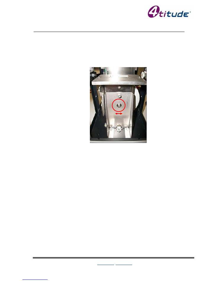
2. Locate the lower M4 screw underneath the platen that receives the PCR / microplate (see
Figure 10). If the unit is under-sealing on the right, loosen the screw and tilt the lift to the left.
If the unit is under-sealing on the left, loosen the screw and tilt the lift to the right.
3. Re-tighten the screw.
Figure 12 - Left-to-Right Adjustment

4s2 Variable Temperature Thermal Sealer Service Manual
4titude Ltd, The North Barn, Surrey Hills Business Park, Damphurst Lane, Wotton, Dorking, Surrey, RH5 6QT, UK
Tel: +44 (0) 1306 884885 Fax: +44 (0) 1306 884886 info@4ti.co.uk www.4ti.co.uk
Page 13
4. Spare Parts & Accessories
Description
Code
Warranty Extension 2
nd
year (12 months)
(must be bought within 3 months of purchase)
4ti-0626
Warranty Extension 2
nd
&3
rd
year (24 months)
(most be bought within 3 months of purchase)
4ti-0627
Adapter for Deep Well Plates
4ti-0615
Adapter for 96 Well PCR Plates
(Incudes 4ti-0612 sealing frame FOC)
4ti-0625
Weighted Platen
(anti roll-up tool)
4ti-0602
Sealing Frame
(Only compatible with 4ti-0625)
4ti-0612
Replacement cardboard packaging & foam inserts
SP-0650/PAC
Rubber Feet, pack of 4
SP-0650/RUF
Front Panel, light grey
(includes keypad and circuit board for key pad)
SP-0650/FPG
Outer metal casing, light grey
SP-0650/OCG
Screw Kit for outer metal casing
SP-0650/SCK
Power socket assembly with fuse housing
SP-0650/POW
Fuse Kit 110V, pack of 10 fuses
SP-0650/FK1
Fuse Kit 230V, pack of 10 fuses
SP-0650/FK2
Main circuit board
SP-0650/MCB
Circuit Board for key pad
SP-0650/CBK
Transformer assembly
SP-0650/TRA
Heating element assembly
SP-0650/HEA
Firmware upgrade cable
SP-0650/FUK