Full Text Searchable PDF User Manual
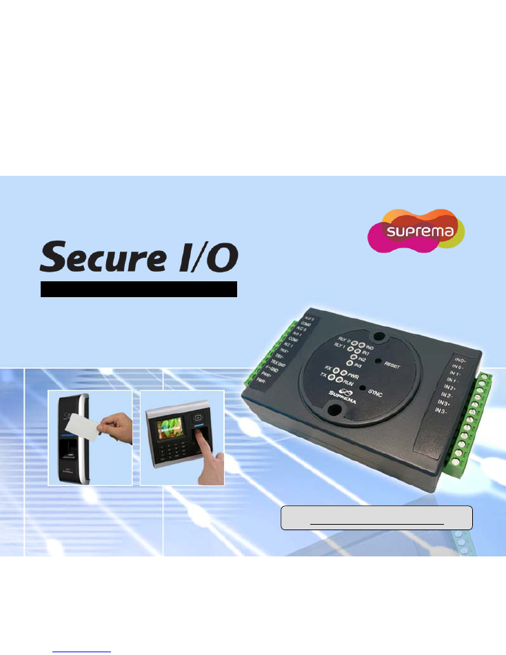
Secrure door control and I/O expansion
www.supremainc.com
(ver 1.0)
Installation Guide
2
Ⓒ
Copyright 2010 Suprema Inc.
Contents
Product Contents
3
Front Panel Description
4
Rear Panel Description 5
Connectors for External Interfaces
6
Installation Example
8
Product Dimension
9
Power Connection
10
RS-485 Connection
11
Relay Connection
12
RTE Switch Connection
14
Fire Alarm Connection
15
System Specifications
16
3
Ⓒ
Copyright 2010 Suprema Inc.
Product Contents
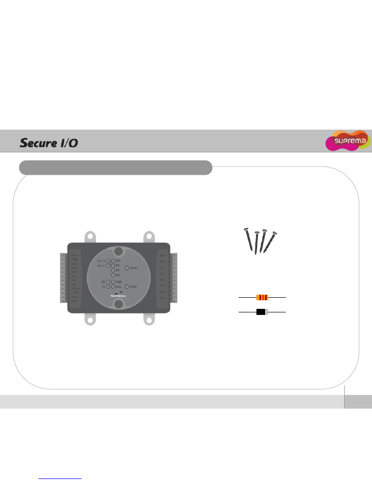
Basic Contents
Product Contents
Secure I/O
Wall mounting screws
120 Ohm Resistor & Diode
4
Ⓒ
Copyright 2010 Suprema Inc.
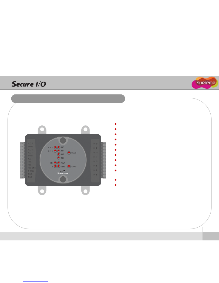
Front Panel Description
RLY0 LED - Status of Relay0
RLY1 LED - Status of Relay1
RX LED - Status of RS-485 Rx signal
TX LED - Staus of RS-485 Tx signal
IN0 LED - Status of Input0
IN1 LED - Status of Input1
IN2 LED - Status of Input2
IN3 LED - Status of Input3
PWR LED - Power status
RUN LED - Status of Secure I/O operation
RESET BUTTON - Secure I/O hardware reset
SYNC BUTTON - Syncronization between Secure I/O and dev
ice (BioStation/ BioEntry Plus) for security by exchanging an e
ncryted keys. This prevents the operation of Secure I/O when
the external device has been exchanged by an intruder. Sync
button should be pressed when a device is set as a host in a
RS-485 loop.
5
Ⓒ
Copyright 2010 Suprema Inc.
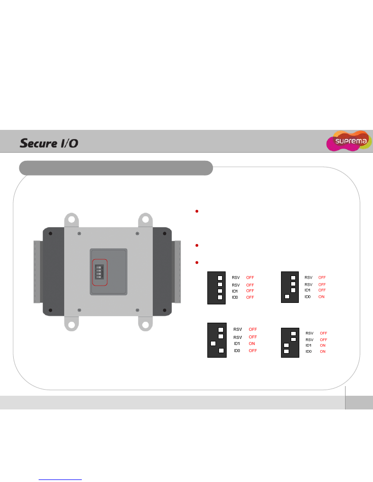
Rear Panel Description
ID = 0
ID = 1
ID = 2
ID = 3
ID0 / ID1 - Dip switch to set an ID of Secure I/O
Since max number of Secure I/O in an RS-485 loop is four,
the ID of Secure I/O should be set among 0, 1, 2, 3.
RSV - reserved for future use
Secure I/O ID setting
6
Ⓒ
Copyright 2010 Suprema Inc.
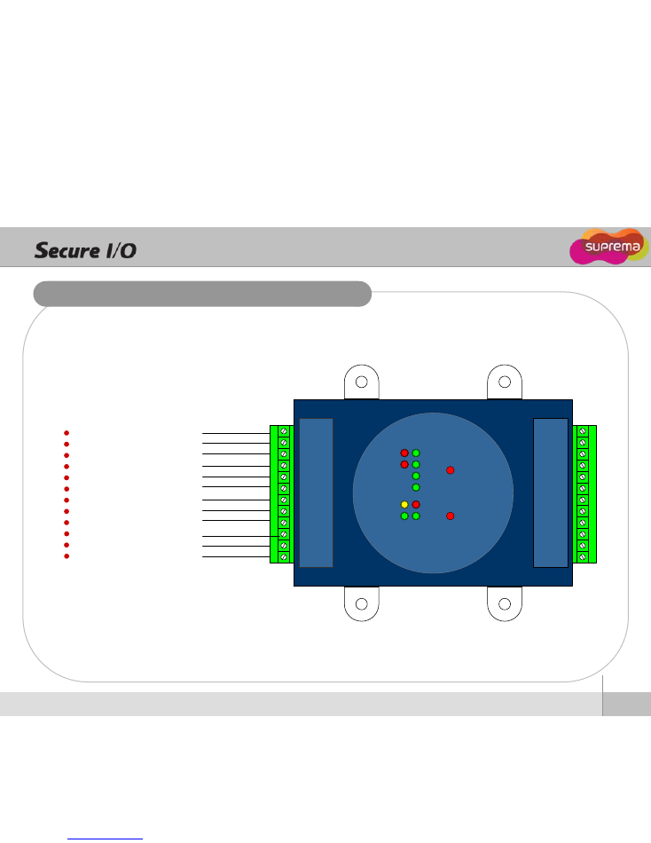
Connectors for External Interfaces 1
Relay Output0 Normal Open
Relay Output0 Common
Relay Output0 Normal Close
Relay Output1 Normal Open
Relay Output1 Common
Relay Output1 Normal Close
RS-485 TRX+
RS-485 TRX-
RS-485 Ground
Frame Ground
Power Input+
Power Input -
IN0
IN1
IN2
IN3
IN0
IN0
RESET
SYNC
RLY0
RLY1
RX
TX
N.O 0
COM 0
N.C 0
N.O 1
COM 1
N.C 1
TRX+
TRX-
TRXGND
PWR+
PWR-
IN 0+
IN 0-
IN 1+
IN 1-
IN 2+
IN 2-
IN 3+
IN 3-
FGND
7
Ⓒ
Copyright 2010 Suprema Inc.
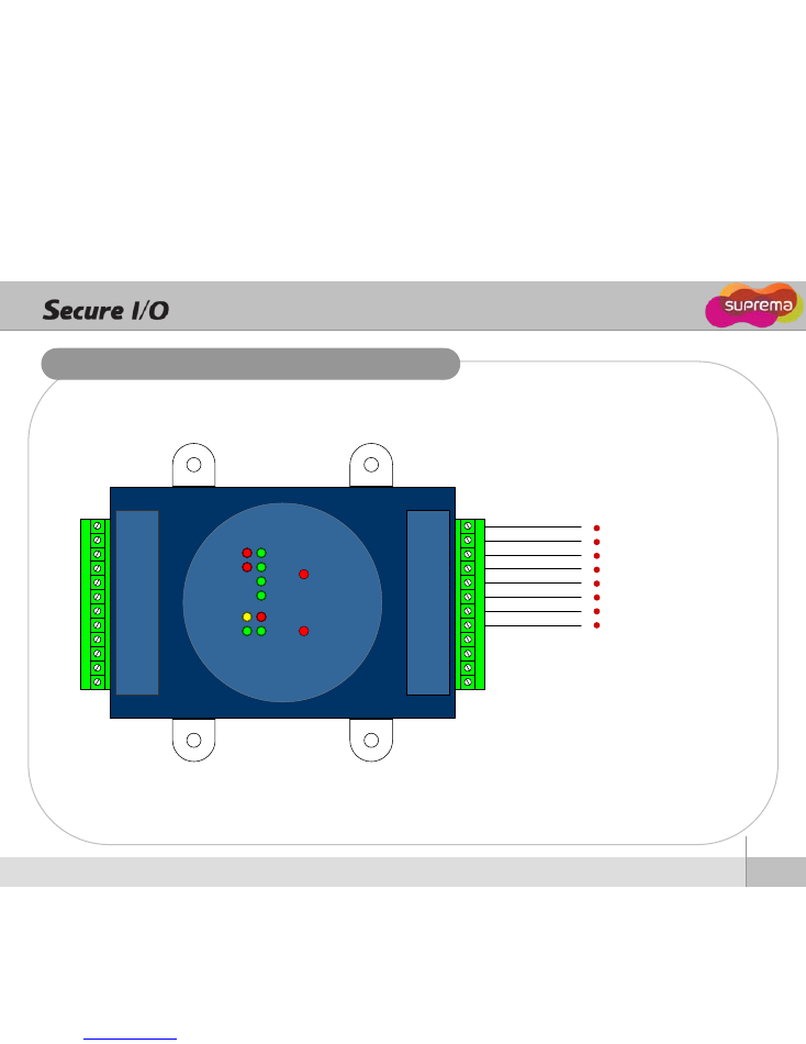
Connectors for External Interfaces 2
IN0
IN1
IN2
IN3
IN0
IN0
RESET
SYNC
RLY0
RLY1
RX
TX
N.O 0
COM 0
N.C 0
N.O 1
COM 1
N.C 1
TRX+
TRX-
TRXGND
PWR+
PWR-
IN 0+
IN 0-
IN 1+
IN 1-
IN 2+
IN 2-
IN 3+
IN 3-
FGND
External Input 0 +
External Input 0 -
External Input 1 +
External Input 1 -
External Input 2 +
External Input 2 -
External Input 3 +
External Input 3 --
8
Ⓒ
Copyright 2010 Suprema Inc.
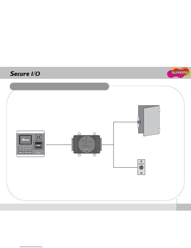
Installation Example
Exit Button
Door Lock
RS-485
Relay Output
External Input
BioStation or
BioEntry Plus
Secure I/O
9
Ⓒ
Copyright 2010 Suprema Inc.
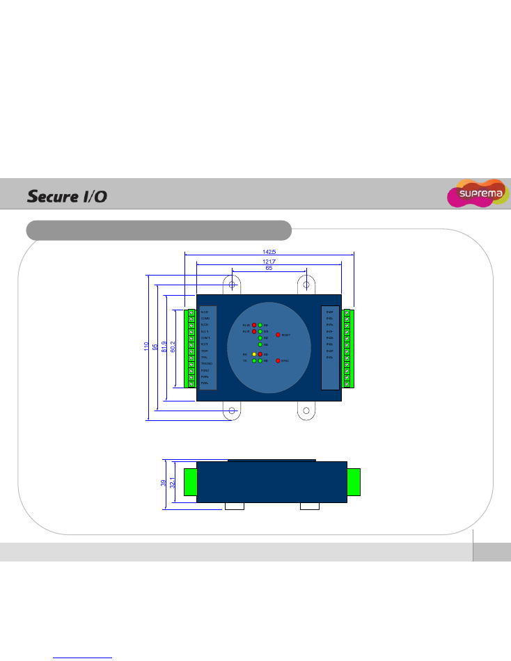
Product Dimension
Top
Side
(unit : mm)
10
Ⓒ
Copyright 2010 Suprema Inc.
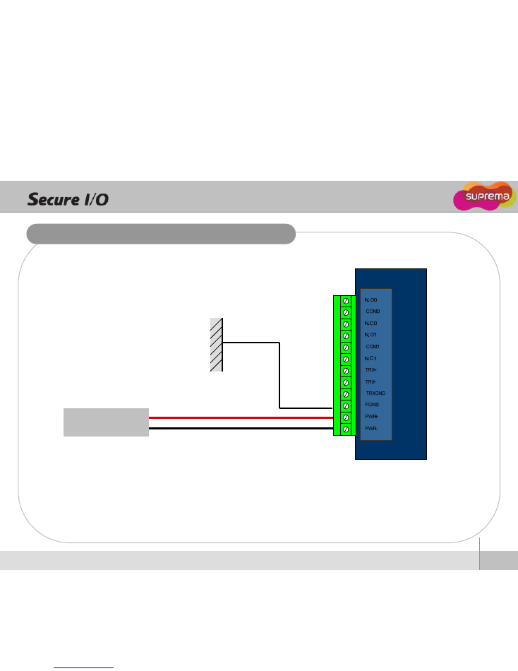
Power Connection
Recommended power supply
z
12V
±
10%, at least 500mA for Secure IO alone installation.
z
Comply with standard IEC/EN 60950-1
z
To share the power with other devices, use a power supply with higher current ratings.
DC 12V Power Source
DC 12V Positive
DC 12V Negative
Earth Ground
11
Ⓒ
Copyright 2010 Suprema Inc.
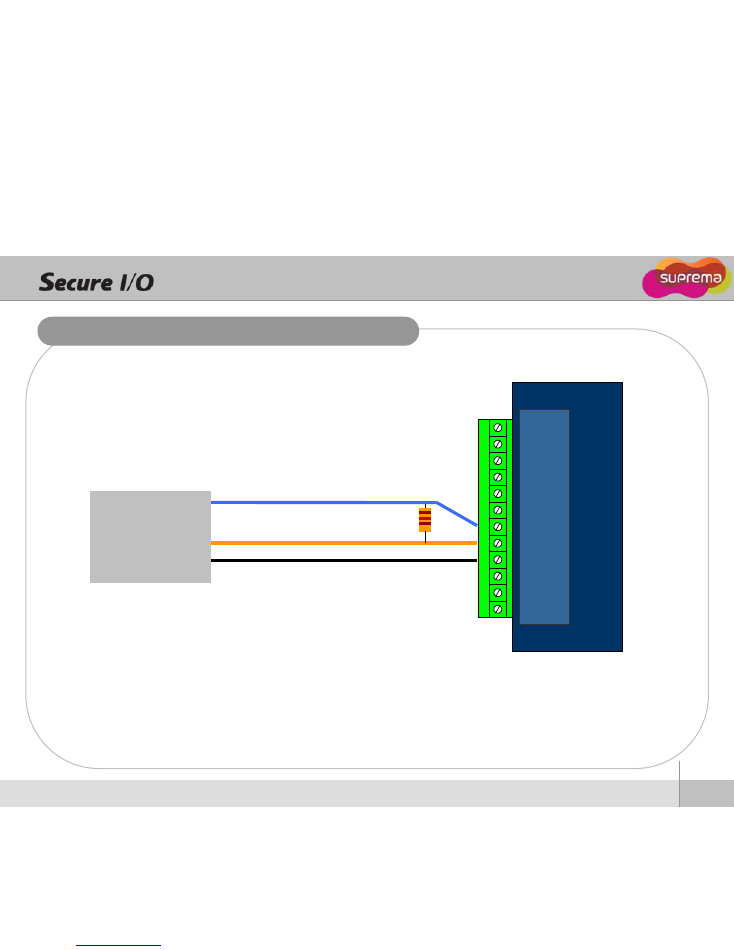
RS-485 Connection
N.O 0
COM 0
N.C 0
N.O 1
COM 1
N.C 1
TRX+
TRX-
TRXGND
PWR+
PWR-
BioStation or BioEntry Plus
RS-485 TRX+
RS-485 TRX-
RS-485 Ground
120 Ohm
resistor
z
In case the length of RS-485 line is so long to affect communication stability, connect the
enclosed 120 Ohm resistor between TRX+ and TRX- connector of Secure I/O
12
Ⓒ
Copyright 2010 Suprema Inc.
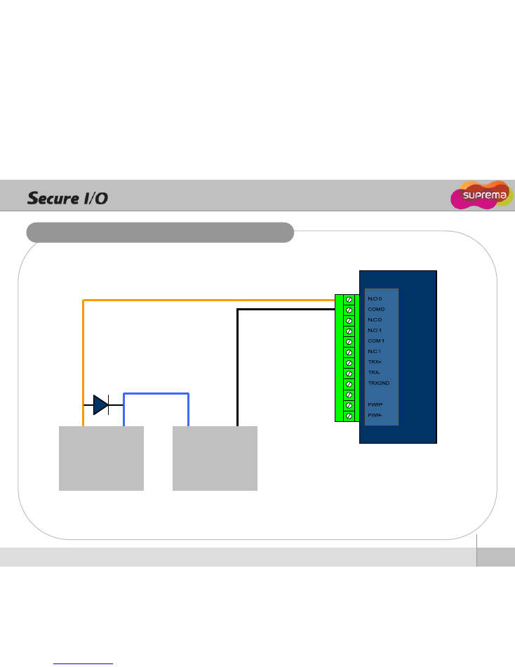
Relay Connection – Fail Secure Lock
Dead Bolt /
Door Strike
+
DC Power
Source
-
z
When using dead bolt or door strike, connect an enclosed diode as in the above diagram.
Anode (line mark) of the diode should be connected to + power (Be careful of the direction)
+
-
13
Ⓒ
Copyright 2010 Suprema Inc.
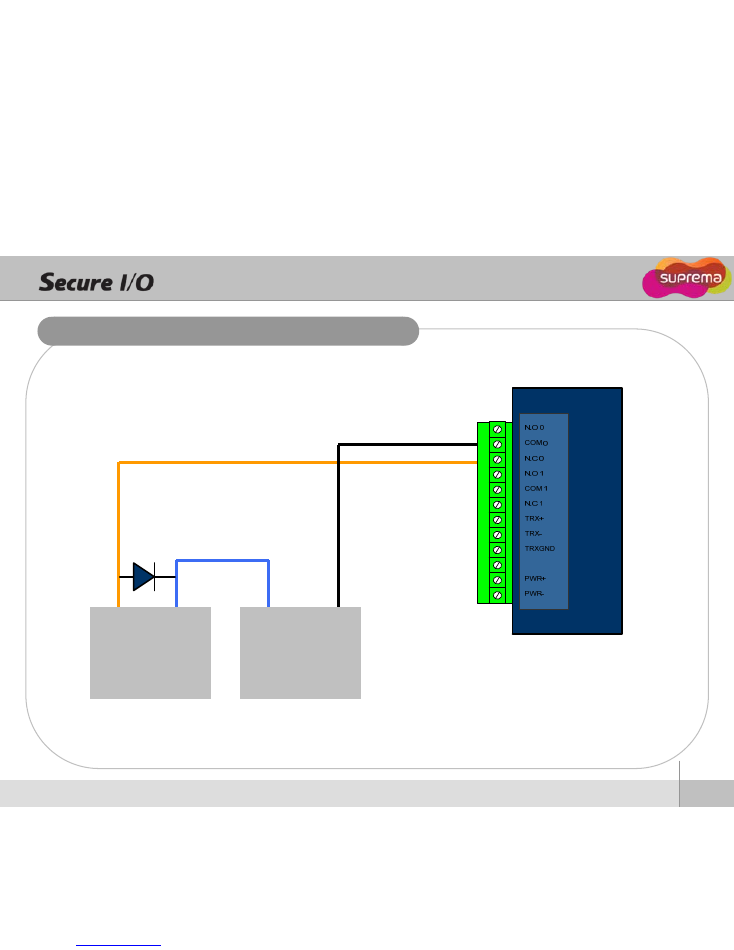
Relay Connection – Fail Safe Lock
Deal Bolt /
Door Strike
+
DC Power
Source
-
z
When using dead bolt or door strike, connect an enclosed diode as in the above diagram.
Anode (line mark) of the diode should be connected to + power (Be careful of the direction)
+
-
14
Ⓒ
Copyright 2010 Suprema Inc.
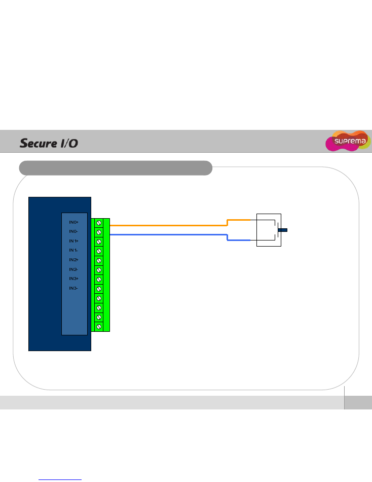
RTE Switch Connection
RTE Switch or
Exit Button
15
Ⓒ
Copyright 2010 Suprema Inc.
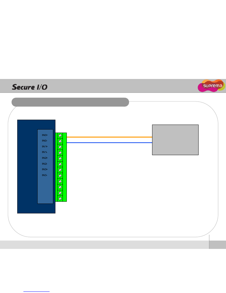
Fire Alarm Connection
Alarm Output+
Alarm Output-
Fire Alarm System
16
Ⓒ
Copyright 2010 Suprema Inc.
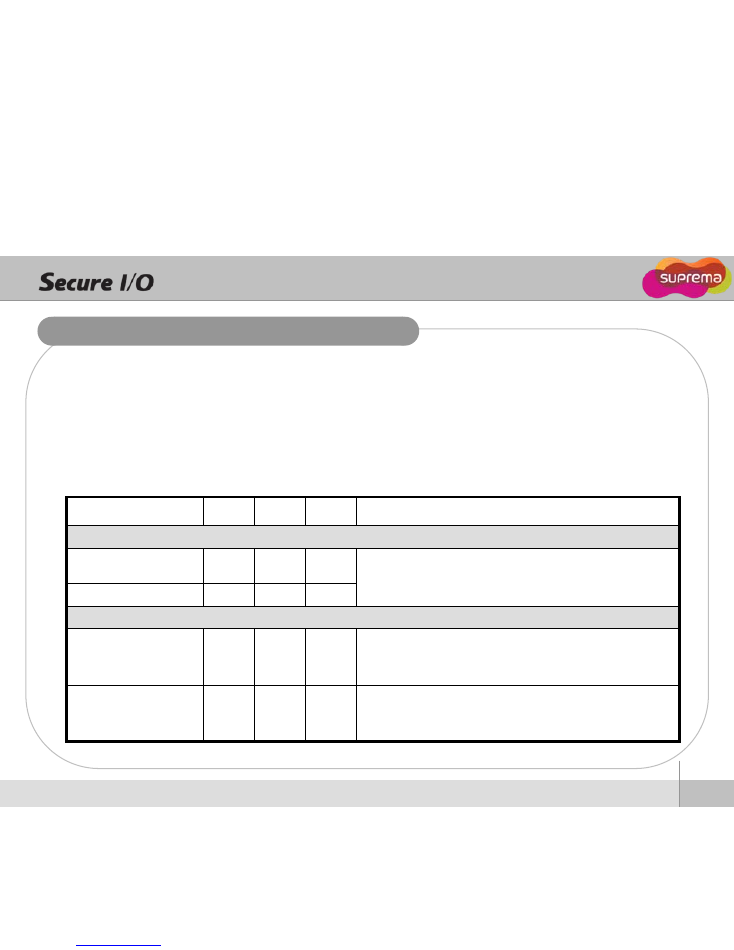
System Specifications
CPU : 8bit, 16MHz Microcontroller
Memory : 32Kbyte Flash
Display : 10ea Status LED
IO : Input X 4Ch, Output X 2Ch, RS-485 X 1Ch
Product size : 142.5 x 110 x 39 mm (width x length x depth)
Min.
Typ.
Max.
Notes
Power
Voltage (V)
10.8
12
13.2
Current (mA)
-
500
800
Relay
Normal switching
capacity(N.O) (Resistive)
-
5A
2A
3A
125VAC
250VAC
30VDC
Normal switching
capacity(N.C) (Resistive)
-
2A
1A
1A
125VAC
250VAC
30VDC

Suprema Inc.
16F Parkview Office Tower, Jeongja-dong, Bundang-gu,
Seongnam, Gyeonggi, 463-863 Korea
E-mail : support@supremainc.com
Website : www.supremainc.com
Functions and specifications of the product are subject to changes without notice due to quality
enhancement or function update. For any inquiry on the product, please contact
Suprema Inc
.