Full Text Searchable PDF User Manual
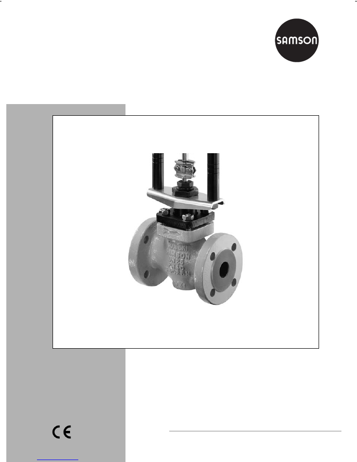
Valve Series V2001
Globe Valve Type 3321
Mounting and
Operating Instructions
EB 8111/8112 EN
Edition February 2004
Fig. 1
⋅
Type 3321 Valve with mounted rod-type yoke for pneumatic or electric actuators (partial view)

Contents
Page
1
Design and principle of operation
. . . . . . . . . . . . . . . . . . . . . . 4
1.1
Technical data . . . . . . . . . . . . . . . . . . . . . . . . . . . . . . . . 5
2
Installation
. . . . . . . . . . . . . . . . . . . . . . . . . . . . . . . . . 6
2.1
Assembling valve and actuator . . . . . . . . . . . . . . . . . . . . . . . . 6
2.2
Mounting position . . . . . . . . . . . . . . . . . . . . . . . . . . . . . . 6
2.3
Strainer, bypass . . . . . . . . . . . . . . . . . . . . . . . . . . . . . . . 6
3
Operation
. . . . . . . . . . . . . . . . . . . . . . . . . . . . . . . . . . 6
4
Maintenance – Replacing parts
. . . . . . . . . . . . . . . . . . . . . . . 7
4.1
Packing . . . . . . . . . . . . . . . . . . . . . . . . . . . . . . . . . . . 7
4.2
Plug . . . . . . . . . . . . . . . . . . . . . . . . . . . . . . . . . . . . . 8
4.3
Seat . . . . . . . . . . . . . . . . . . . . . . . . . . . . . . . . . . . . . 8
5
Description of the nameplate
. . . . . . . . . . . . . . . . . . . . . . . . . 9
6
Dimensions and weights
. . . . . . . . . . . . . . . . . . . . . . . . . . . 9
7
Customer inquiries
. . . . . . . . . . . . . . . . . . . . . . . . . . . . . . 10
Contents
Note!
Non-electrical control valves, whose valve bodies are not lined with an
insulating material
coating
, do not have their own potential ignition source according to the risk assessment
stipulated in EN 13463-1: 2001, paragraph 5.2, even in the rare incident of an operating
fault. Therefore, such valve versions do
not
fall within the scope of Directive 94/9/EC.
Refer to paragraph 6.3 of EN 60079-14:1977 VDE 0165 Part 1 concerning connection to
equipotential bonding system.
2
EB 8111/8112 EN

General safety instructions
The control valve may only be mounted, started up or serviced by fully trained
and qualified personnel, observing the accepted industry codes and practices.
Make sure employees or third persons are not exposed to any danger.
All safety instructions and warnings in these instructions, particularly those con-
cerning installation, start-up, and maintenance, must be observed.
The control valve fulfills the requirements of the European Pressure Equipment
Directive 97/23/EC. Valves with a CE marking have a declaration of conform-
ity that includes information on the applied conformity assessment procedure.
The declaration can be viewed and downloaded on the Internet at
http://www.samson.de.
For appropriate operation, make sure that the control valve is only used in
areas where the operating pressure and temperatures do not exceed the oper-
ating values based on the valve sizing data submitted in the order. The manu-
facturer does not assume any responsibility for damage caused by external
forces or any other external influence!
Any hazards which could be caused in the control valve by the process me-
dium, operating pressure, signal pressure or by moving parts are to be
prevented by means of the appropriate measures.
Proper shipping and appropriate storage are assumed.
Important!
For installation and maintenance work on the valve, make sure the relevant
section of the pipeline has been depressurized and, depending on the process
medium used, drained as well. If necessary, allow the control valve to cool
down or warm up to reach ambient temperature prior to starting any work on
the valve.
When working on the valve, make sure that the supply lines for the air supply
as well as the control signal are disconnected to prevent any hazards that
could be caused by moving parts.
Special care is needed with pneumatic control valves when the actuator
springs are pretensioned. These actuators are labeled correspondingly and
can also be identified by three long bolts at the bottom of the actuator. Prior to
starting any work on the valve, you must relieve the compression from these
pretensioned springs.
Safety instructions
EB 8111/8112 EN
3
1 Design and principle of operation
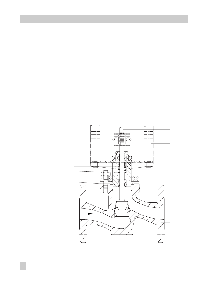
The Type 3321 Single-seated Globe Valve
is based on the modular principle and can
be combined with pneumatic as well as elec-
tric actuators:
Type 3372-04xx Actuator attached to
the V 2001-P Pneumatic Control Valve
Type 3372-05xx Actuator attached to
the V 2001-IP Electropneumatic Control
Valve
Type 5824 or 3374 Actuator attached to
the V 2001-E1 or V 2001-E3 Electric
Control Valve (also refer to T 8111 EN).
The process medium flows through the valve
in the direction indicated by the arrow. The
valve plug position determines the cross-sec-
tional area of flow between the seat (2) and
the plug (3). The position of the plug is
changed by the control signal acting on the
actuator.
The plug stem is sealed by a spring-loaded
PTFE ring packing (4.2) and connected to
the actuator stem (8.1) by means of a stem
connector (7).
Fig. 2
⋅
Sectional drawing
1
Valve body
1.1 Nuts
1.2 Gasket
2
Seat
3
Plug
4.1 Spring
4.2 Packing
4.3 Washer
5
Valve bonnet
5.1 Flange
5.2 Threaded bushing
6
Nut
7
Stem connector
8.1 Actuator stem
8.2 Rod-type yoke
8.3 Rod nut
8.1
8.2
7
5.2
6
8.3
5
5.1
3
2
1
4.2
4.3
4.1
1.1
1.2
4
EB 8111/8112 EN
Design and principle of operation
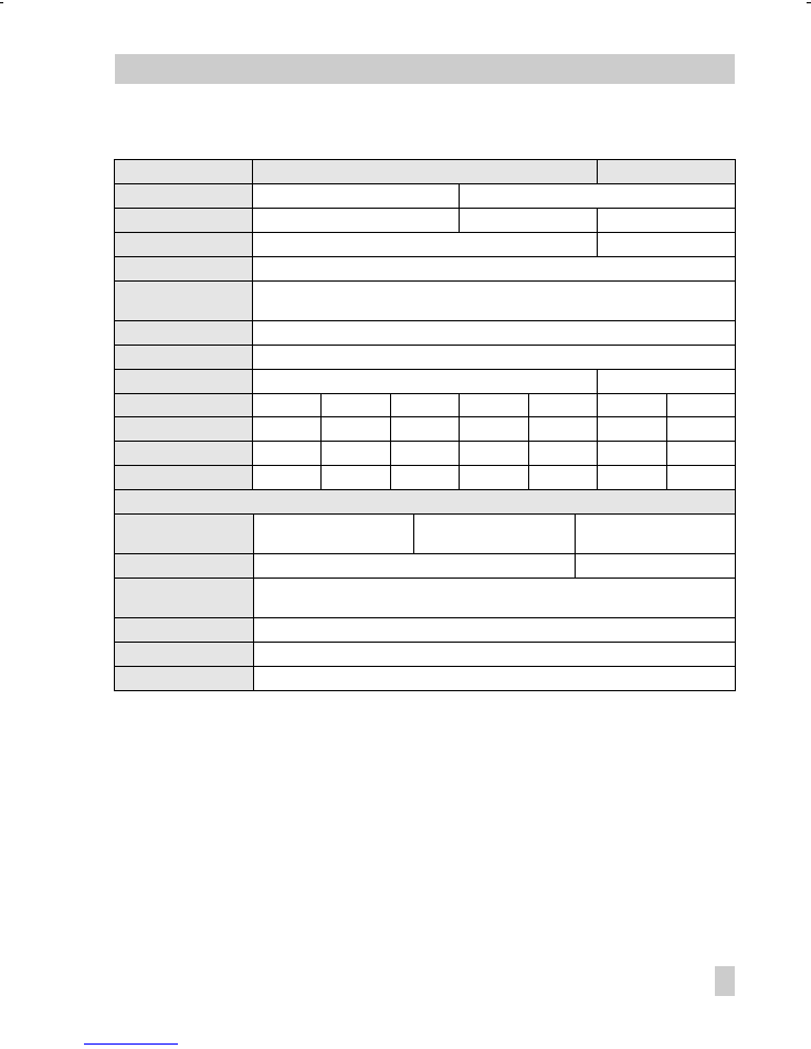
1.1 Technical data
Valve
DN 15 to 50
ANSI 1/2" to 2"
Material
Cast iron
Cast steel
Nominal pressure
10, 16
16, 25, 40
Class 150, Class 300
Flange connection
Type B1 EN 1092-1
Raised face
Seat-plug seal
Metal sealing or soft sealing:
Leakage class
acc. to IEC 534-4
Metal sealing: IV (0.01 % K
VS
)
Soft sealing: VI (bubble-tight)
Characteristic
Equal percentage
Rangeability
50 : 1
Temperature range
–10 to 220 °C
15 to 430 °F
DN
15 / 1/2"
1)
15 / 1/2"
20 / 3/4"
25 / 1"
32
40 / 1 1/2"
50 / 2"
K
VS
values
m
3
/h 0.63
⋅
0.25
1.6
⋅
4
2.5
⋅
6.3
4.0
⋅
10
6.3
⋅
16
10
⋅
25
16
⋅
35
C
V
values
0.75
⋅
0.3
2
⋅
5
3
⋅
7.5
5
⋅
12
12
⋅
30
20
⋅
40
Seat diameter
mm
6
⋅
3
12
12
⋅
24
12
⋅
24
12
⋅
32
24
⋅
38
32
⋅
48
Materials
Valve body
Cast iron
EN-JL1040 (GG-25)
2)
Cast steel
1.0619 (GSC25)2)
ANSI
A216 WCB
Valve bonnet
1.0460 (C 22.8)
2)
A105
Seat and plug
1.4305/for seats in DN 32 and larger: 1.4104
Sealing ring of the soft seal: PTFE with glass fiber
Guide bushing
1.4104
Packing
PTFE V-ring packing with carbon; spring: 1.4310
Body gasket
Metal graphite
1)
Special version
2)
Former material designation
EB 8111/8112 EN
5
Technical data

2 Installation
2.1 Assembling valve and actuator
The valve and the actuator are packed indi-
vidually and must be assembled on site.
To do this, proceed as follows:
1. Remove the nut (6) from the valve bon-
net.
2. Slightly retract the actuator stem (8.1)
and place the actuator with its rod-type
yoke on the valve bonnet. Secure with
the nut (SW 36). Observe a tightening
torque of min. 150 Nm.
3. Extend the actuator stem until it contacts
the plug stem.
4. Position the stem connector clamps and
screw tight.
Caution!
Under no circumstances must the rod nuts
(8.3) of the rod-type yoke be unscrewed.
For further details, refer to the mounting
and operating instructions of the respective
actuator.
2.2 Mounting position
The valve can be mounted in any position.
However, strictly observe the limitations re-
sulting from the type of actuator used.
Caution!
The valve must be installed free of stress
and free of excessive vibrations. If necess-
ary, support the pipelines near the connec-
tions. Do not install supports on the valve or
on the actuator. Thoroughly flush the
pipeline prior to installation of the valve.
2.3 Strainer, bypass
We recommend that you install a SAMSON
Type 2 Strainer upstream of the valve.
We also recommend that you install a shut-
off valve both upstream of the strainer and
downstream of the control valve as well as
a bypass line so that the plant need not be
shut down for maintenance routines.
3 Operation
As the operating instructions depend on the
actuator used, refer to the corresponding
mounting and operating instructions for de-
tailed information.
6
EB 8111/8112 EN
Installation
4 Maintenance – Replacing parts
The control valve is subject to wear espe-
cially at the seat, plug, and packing. De-
pending on the application conditions that
prevail, the valve must be inspected at ap-
propriately scheduled intervals to prevent
any problems before they occur.
If any leaks occur to the atmosphere, the
packing may have become untight.
If the valve does not seal properly, this may
be because tight shut-off is prevented by
dirt or other impurities between the seat
and plug or because the seating surfaces
have been damaged.
We recommend removing the parts, thor-
oughly cleaning them, and replacing them
with new parts, if necessary.
Caution!
If you intend carrying out mainten-
ance work on the valve, first relieve
the corresponding plant section of
pressure and, depending on the pro-
cess medium, drain it as well.
Let the plant section cool down to
reach ambient temperature, if
necessary.
Prior to starting any work, discon-
nect the electric or pneumatic con-
trol signal for the actuator. On pneu-
matic actuators, additionally remove
the signal pressure line.
As the process medium cannot drain
completely out of the valve, be
aware that some of the process me-
dium could still be in the valve.
We recommend that you remove the
valve from the pipeline.
Note!
The tightening torques and special tools re-
quired for installing and removing the seat
are listed in the table on page 8. For further
details, refer to the SAMSON Special Tools
WA 029 EN.
Important!
Always separate the actuator and the valve
prior to carrying out repairs! Separate the
actuator from the valve by removing the
stem connector clamps (7) and the nut (6).
Then lift the actuator off the valve. Note that
the rod nuts (8.3) of the rod-type yoke must
not be unscrewed under any circumstances.
4.1 Packing
1. Unscrew the nuts (1.1) and remove the
valve bonnet (5) and flange (5.1).
2. Check the gasket (1.2) in the valve
body for damage. We recommend that
you replace the gasket.
3. Screw off the threaded bushing (5.2)
and pull out the plug (3).
4. Pull out the damaged packing (4.2)
using an appropriate tool.
Remove the washer (4.3) and spring
(4.1) and clean the packing chamber.
5. Apply lubricant (order no. 8150-0111)
to the individual parts of the new pack-
ing and the plug stem. Insert the
plug (3) in the valve bonnet (5).
6. Place the valve bonnet with flange on
the valve body and secure with
nuts (1.1). Observe the tightening tor-
ques given in the table on page 8.
EB 8111/8112 EN
7
Maintenance – Replacing parts
7. Insert the spring (4.1) and washer (4.3)
and carefully slide the new pack-
ing (4.2) over the plug stem into the
packing chamber. Screw in the threaded
bushing (5.2) and tighten.
4.2 Plug
When replacing the plug, you should also
replace the packing (4.2) and the gas-
ket (1.2).
To exchange the plug, carry out the same
steps as described in section 4.1. However,
install a new plug instead of the used one.
Apply lubricant (order no. 8150-0111) to
the plug stem prior to installation.
4.3 Seat
1. Unscrew the nuts (1.1). Lift the valve
bonnet (5) and flange (5.1) off the
valve body (1).
2. Unscrew the seat (2) using the appropri-
ate seat wrench.
3. Apply lubricant (order no. 8150-0119)
to the thread and the sealing cone of
the new seat and screw in.
4. Place the valve bonnet with flange on
the valve body and secure with nuts
(1.1). Observe the tightening torques!
Sockets / seat wrenches / tightening torques
DN (size)
15...25
(1/2...1")
32...50
(1 1/2...2")
Socket / seat wrench
Order no.
9932-3330
1280-3009
Seat thread in mm
Tightening torque
±
10 %
M32 x 1.5
170 Nm
M58 x 1.5
500 Nm
Body nuts (1.1)
Tightening torque +10 %
M10
10 Nm
M12
30 Nm
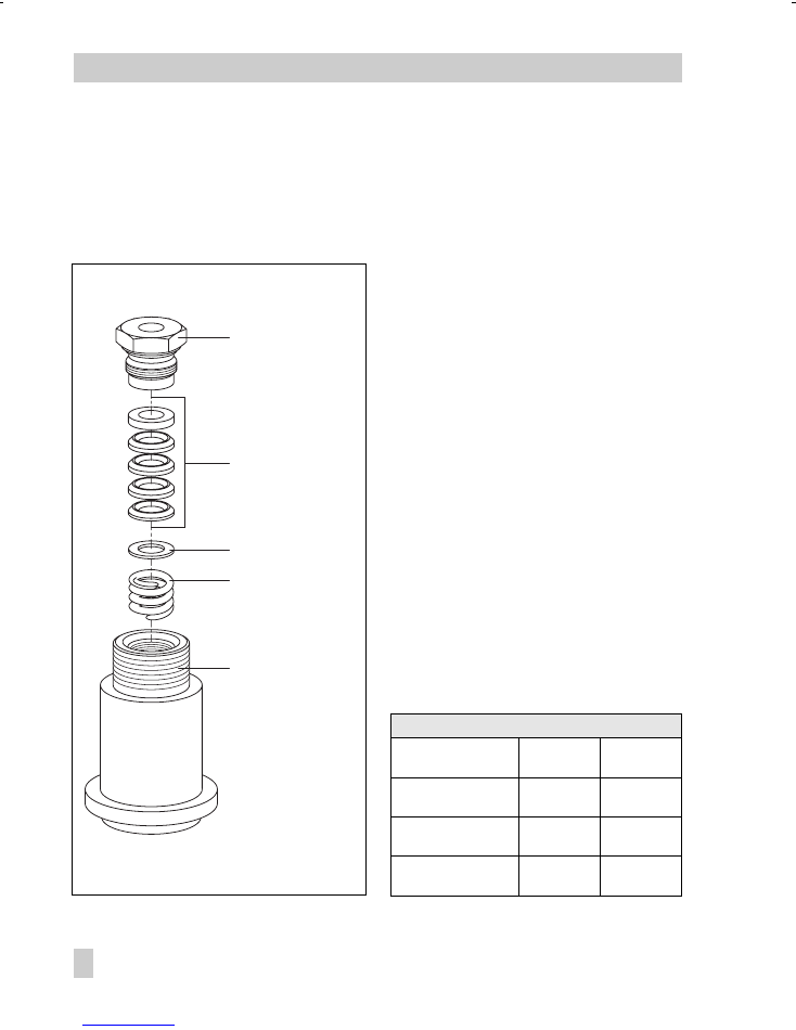
Fig. 3
⋅
Stuffing box parts
5.2
4.2
4.3
4.1
5
4.1 Spring
4.2 Packing
4.3 Washer
5
Valve bonnet
5.2 Threaded bushing
8
EB 8111/8112 EN
Maintenance – Replacing parts
5 Description of the nameplates
6 Dimensions and weights
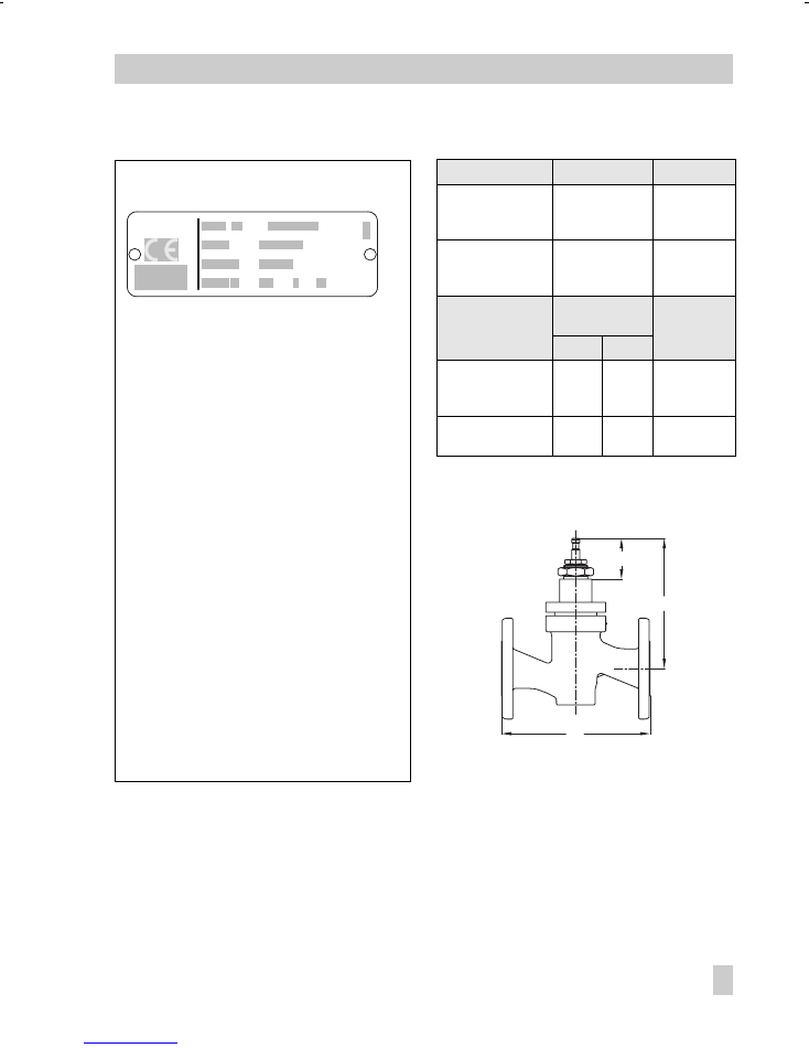
Fig. 4
⋅
Nameplate
DIN
DN (mm)
L mm
H mm
15
20
25
130
150
160
160
32
40
50
180
200
230
165
ANSI
Size (in)
L in
Class
H in
150
300
1/2"
3/4"
1"
7.25
7.25
7.25
7.5
7.62
7.75
6.3
1 1/2"
2"
8.75
10.0
9.25
10.5
6.5
1
CE marking or "Art. 3, Abs. 3" (see Article 3,
§3 of PED), where applicable
2
Identification number of notified body, fluid
group, and category, where applicable
3
Type designation
4
Modification index of valve
5
Material
6
Year of manufacture
7
Valve size DIN: DN, ANSI: Size
8
Permissible excess pressure at room temperature
DIN: PN, ANSI, CL
9
Order number with modification index
10 Item position in the order
11 Flow coefficient DIN:
K
VS
value, ANSI:
C
V
value
12 Characteristic:
%
Equal percentage,
Lin
Linear
DIN:
A/Z
, ANSI:
O/C
(open/closed)
13 Seal
ME
Metal,
ST
Stellited,
Ni
Nickel-plated,
PT
Soft sealing with PTFE,
PK
Soft sealing with PEEK
14 Pressure balanced DIN:
D
, ANSI:
B
15 Flow divider
I
or
III
H
50(1.96)*
L
* Valve CLOSED
3
4
5
9
10
7
8
11 12
13
14 15
2
1
6
SAMSON
Made in
Germany
-
EB 8111/8112 EN
9
Dimensions and weights

7 Customer inquiries
If you have any questions, submit the follow-
ing details:
Type designation and order number
(indicated on the nameplate)
Production number, nominal size, and
valve version
Pressure and temperature of the medium
Flow rate in m
3
/h
Bench range (signal pressure range, e.g.
1.4 to 2.3 bar) of the pneumatic actuator
Installation drawing
10
EB 8111/8112 EN
Customer inquiries

EB 8111/8112 EN
11

SAMSON AG
⋅
MESS- UND REGELTECHNIK
Weismüllerstraße 3
⋅
60314 Frankfurt am Main
⋅
Germany
Phone: +49 69 4009-0
⋅
Fax: +49 69 4009-1507
Internet: http://www.samson.de
EB 8111/8112 EN
S/Z
2004-
06