Full Text Searchable PDF User Manual

NOx
BOX
i
Operating Instructions
®
1
www.noxboxltd.com
Bedfont Scientific Ltd, Station Road, Harrietsham, Maidstone, Kent, ME17 1JA
+44 (0)1622 854868
+44 (0)1622 854860
ask@noxboxltd.com
www.noxboxltd.com
Issue 6.0 (Software V.17.1) September 2015. Part No: LAB636
© NOxBOX Ltd
NOxBOX Limited reserves the right to change or update this literature without prior notice. Registered office: England and Wales. Registered No: 9563860
ISO 9001:2008
Cert No. FM 31664
ISO 13485:2003
Cert No. MD 502905
Set- Up
Before you use the Bedfont NOxBOX
i
intelligent Nitric Oxide delivery and monitoring system it is important to follow these steps:
Ensure the device does not require maintenance (monthly) and that the maintenance is not due during the expected duration of the therapy such as:
• NO sensor high calibration
• NO
2
sensor high calibration
• Pump calibration
• Vent calibration
Checklist
• Ensure the device is clean and free from damage
• Ensure the water trap is empty and has been cleaned from previous use
• Ensure all single use items from previous patient have been discarded
Equipment you will need for set-up:
• A NOxBOxi system test kit (NOXBOX-I TEST)
• A NOXKIT (inspiratory limb size dependant)
• Two cylinders of delivery gas
• A 22mm one-way valve for HFO ventilator circuits (FXS555)
Additional items
• NOxAIR Environmental monitors
• Manual bagging kit
NOTE: If you do not have the parts listed above or the device has not been maintained the NOxBOX
i
may not be suitable for use and you may be unable to
set-up the device. Failure to follow these procedures may result in harm to to the operator or the patient.
NOx
BOX
i
Operating Instructions
®
2
www.noxboxltd.com
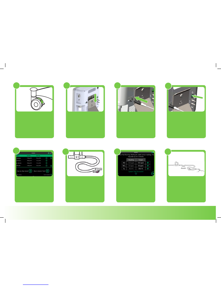
Setup
Engage trolley brakes to
stabilise system prior to use.
To attach monitor to trolley,
carefully drop the monitor
over the attachment plate.
Connect power supply to
suitable rated mains outlet.
Press power button to start
system.
Once zero test is complete,
follow instructions on
screen to set-up system.
Experienced users may
choose to skip directly to
system tests or skip to dose.
System test circuit set-up:
NOxFlowTM arrow points in
direction of flow. 1m vent
tubing between sample
point and NOxFlow
TM
.
Perform system
test to ensure correct system
functionality prior to
connecting to patient.
Connect to patient circuit;
sample near patient Y-piece.
Retain NOxFlowTM
orientation for flow and 1m
distance from sample point.
1
2
3
4
5
6
7
8
NOx
BOX
i
Operating Instructions
®
3
www.noxboxltd.com
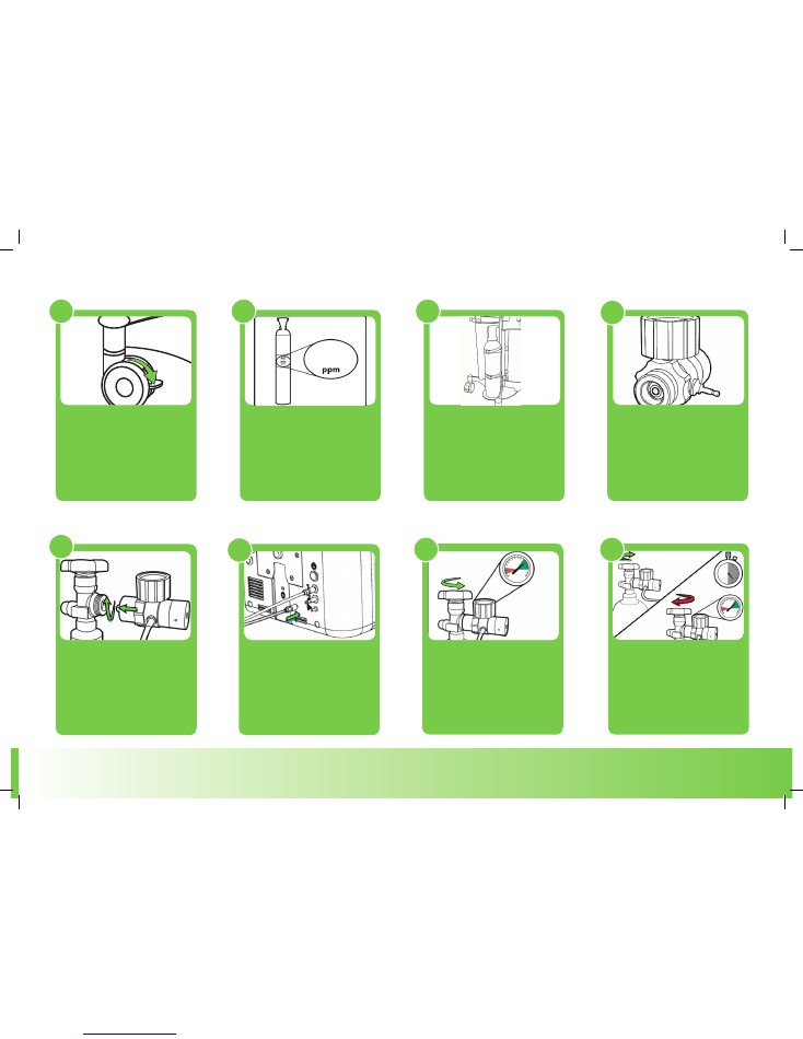
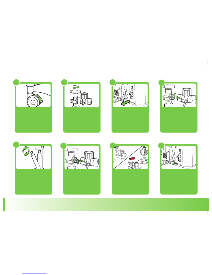
Perform a leak test: open the
cylinder valve then close.
Observe gauge for 30
seconds, needle should
remain sta>onary.
Engage trolley brakes to
stabilise system prior to
changing cylinder.
Check cylinder concentration
matches the setting for the
system.
Check regulator surfaces and
O rings are damage free. Do
not use damaged equipment.
Attach regulator to cylinder.
Screw firmly by hand. Attach
supply line to regulator.
Apply supply line to port on rear
of monitor
1
2
3
5
Slowly open cylinder valve.
Read gauge. If needle in red
zone, replace cylinder before
starting treatment.
Perform a leak test: open the
cylinder valve then close.
Observe gauge for 30
seconds, needle should
remain stationary.
4
6
8
Cylinder setup
7
Load cylinders onto trolley.
Secure with straps.
1000
NOx
BOX
i
Operating Instructions
®
4
www.noxboxltd.com
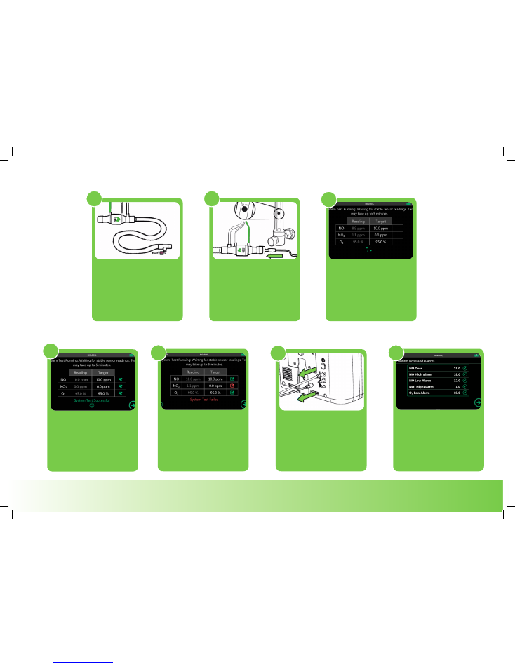
System tests
System test circuit set-up:
NOxFlow arrow points in
direction of flow. 1m vent
tubing between sample
point and NOxFlow.
Re-open NO cylinder.
Connect O
2
supply to
NOxFlow
TM
inlet. Set O
2
flow
to 10 L/min. Press “Next” on
system screen to run test.
System test takes approx.
5 minutes to run. This purges
NO
2
and ensures correct
NOxBOX
i
operation.
System test passed. Stop O
2
flow
and disconnect from NOxflow.
Ready to connect to patient.
System test failed. Check:
NOxFlow orientation; O2
flow at 10 L/min, NO cylinder
connected and valve open.
Re-run test.
If not using in next 10 mins: Unit
may time out and may require
you to repeat step 4.
Connect to patient circuit.
Enter dose and check alarm
levels before commencing
treatment.
1
2
3
4
5
6
7
NOx
BOX
i
Operating Instructions
®
5
www.noxboxltd.com
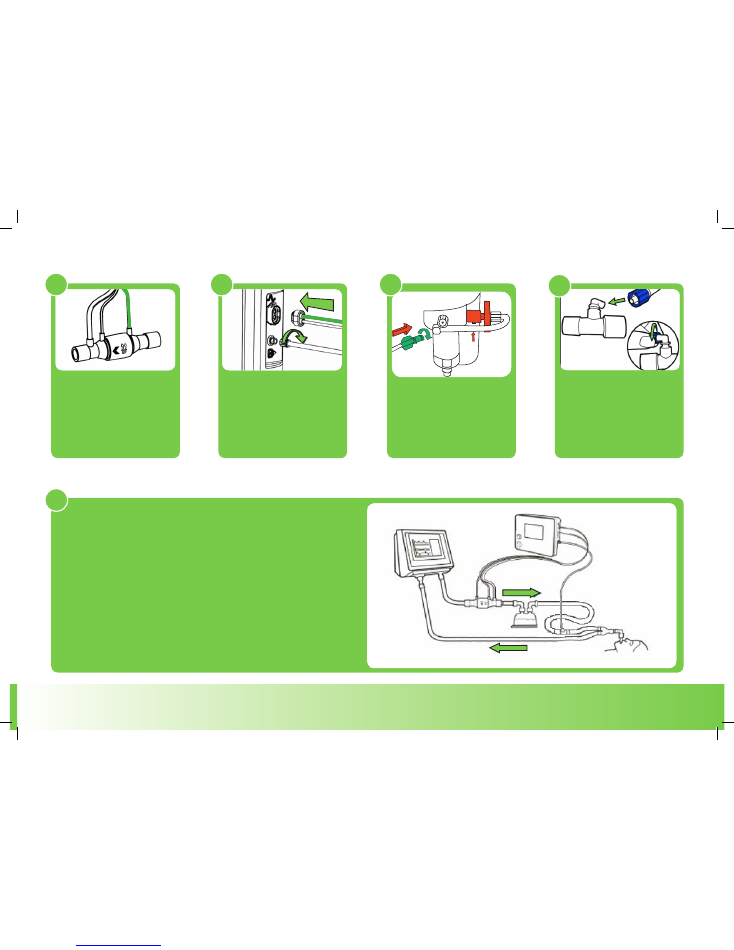
Ventilator connections
The NOxFlow
TM
is single
patient use. Unwrap and
carefully uncoil the lines.
Push and click-to-lock twin
sensor line to unit.
Twist dose line luer to unit.
Select a vent connector with
luer port from the NOXKITTM.
Connect the male luer of the
sample line.
1
2
3
4
NOxFlow
TM
is situated in the inspiratory limb,
before the humidifier.
The sample line is up to 30cm from patient to the patient Y-piece.
NOxFlow should be approx. 1 metre back from the sample
point. Ideal range 0.7 m – 1.3 m.
For system test, high frequency and manual bagging circuit
diagrams please refer to Technical Guide.
5
Change sample line and
hydrophobic fliter.
NOx
BOX
i
Operating Instructions
®
6
www.noxboxltd.com
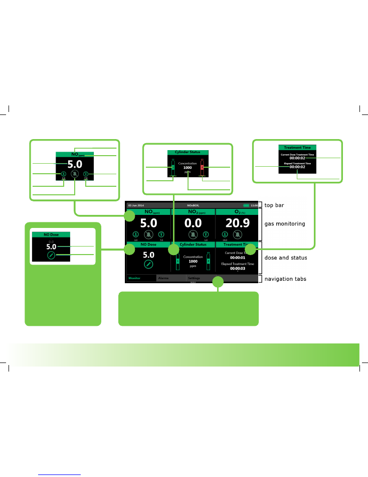
Dose setting & main screen features
The navigation tabs access the alarm history and user settings screens.
Alarm history: shows last 10 alarms for current treatment. Unresolved
alarms are listed at the top.
User settings: change user settings, access Manual Override
calculator, Sensor Zero and Service Engineer area.
To set or change dose press ‘edit
dose’ . The NOxBOX
i
will then
guide you through setting the
dose and high/low alarms. Once
confirmed the delivery and
monitoring will adjust
accordingly.
Maximum dose - 80ppm
Minimum dose - 0.1ppm
dose setting
edit dose
monitored gas
units
upper alarm
adjustment
upper alarm value
lower alarm
adjustment
lower alarm value
mute button (inactive)
monitored
value
supply
indicator
(depleated)
cylinder 2
supply concentration
supply
indicator
(gas available)
cylinder 1
time at
current dose
days:hours:mins
second timing marker
total treatment
time
days:hours:mins
NOx
BOX
i
Operating Instructions
®
7
www.noxboxltd.com
Cylinder replacement
Engage trolley brakes to
stabilise system prior to
changing cylinder.
Fully close cylinder valve.
Check regulator gauge
pressure is relieved and
remove regulator from
depleted cylinder.
Remove depleted cylinder from
trolley and replace with new
supply cylinder. Check the
concentration matches the value
displayed on-screen.
Check O rings and attach
regulator to new
cylinder.
1
2
5
Perform a leak test: Slowly open
the cylinder valve then close.
Observe gauge for 30 seconds,
needle should remain
stationary.
Purge pressure from hose, then
reconnect the hose to inlet port
monitor. Open valve on cylinder
fully.
7
8
3
4
Perform a leak test: open the
cylinder valve then close.
Observe gauge for 30
seconds, needle should
remain sta>onary.
6
Detach hose from monitor and
depressurise on purge needle.
NOx
BOX
i
Operating Instructions
®
8
www.noxboxltd.com
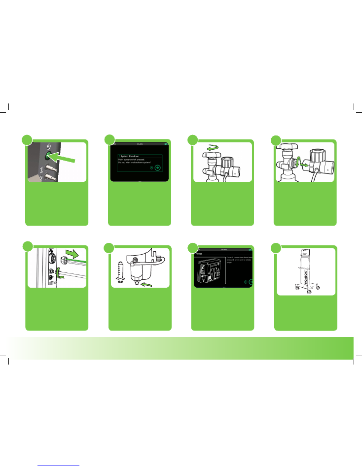
Confirm on-screen that
shutdown is required. Follow
on-screen instructions.
Fully close each cylinder and
depressurise the supply lines
using the purge needle.
Check regulator gauge
pressure is relieved and
remove regulator from each
cylinder and stow on system
trolley.
Remove all single patient use
devices from monitor and
dispose of according to local
regulations.
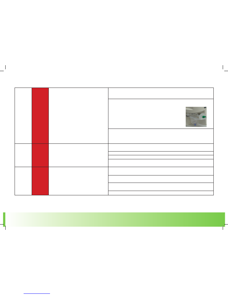
Drain water trap and dispose of
drainage syringe.
On completion of last
instruction screen, system will
purge and shutdown safely
ready for storage.
2
3
4
5
6
7
Shutdown
Remove power supply and
store on trolley for transport.
Ensure system is attached to
suitable mains supply whilst in
storage.
8
When ready to shutdown the
system, briefly press the power
button on the monitor.
1

NOx
BOX
i
Operating Instructions
®
9
www.noxboxltd.com
Troubleshooting Guide
ALARMS TROUBLESHOOTING
The NOxBOX
i
is equipped with audible and visible alarm notifications; this chapter is a guide to the alarm conditions that can occur and common actions for alarm resolution. All alarms
are graded into high priority or medium priority alerts.
NOTE: In all instances of alarms sounding, the health and condition of the patient must be ensured before attempting to resolve any issue with the NOxBOX
i
system.
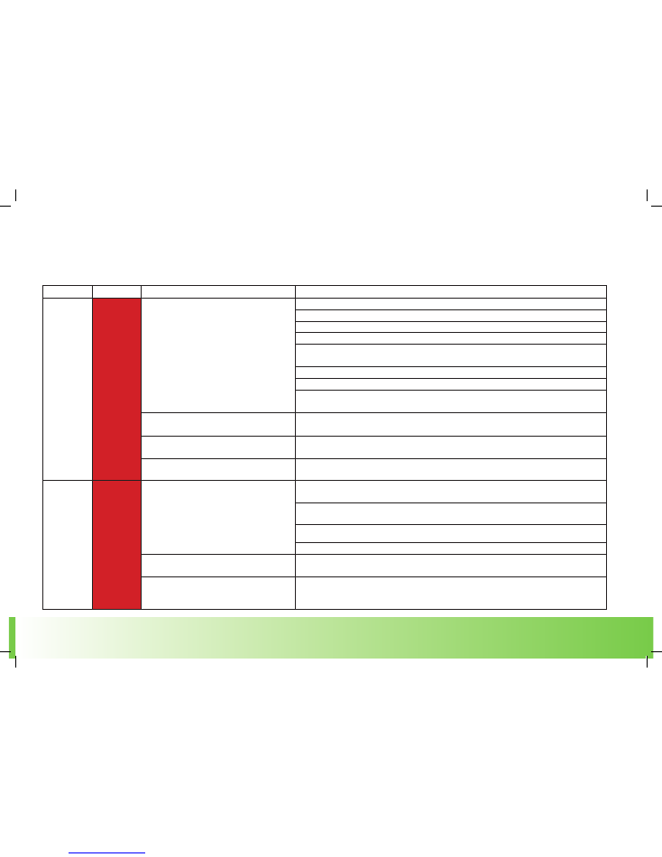
Alarm Priorities
The system alarms are colour coded to help identify priority of detected issue. Additionally, the two alarm priorities each have an audible warning to help differentiate them.
Priority
Colour & Tone
Meaning
High
Red
5 tone pattern & Red L.E.D.
alarm strip.
Critical problem detected. Condition poses immediate threat to patient health or correct
functioning of the NOxBOX
i
monitor. Alarm condition should be diagnosed and resolved
immediately.
Medium
Amber
3 tone pattern
Problem detected. Condition may impair the functioning of the NOxBOX
i
. If left unresolved, problem may
worsen and cause a high priority alarm condition.

NOx
BOX
i
Operating Instructions
®
10
www.noxboxltd.com
Notifications at Switch on
The below are a series of notifications which may be seen at start-up (before the home screen) if an issue is detected with the NOxBOX
i
.
Troubleshooting Guide
Notification
Priority
Possible Cause
Recommended
NOxBOXi System
Diagnostics
High
The NOxBOXi performs self-tests at start-up and during operation
to ensure safe performance is maintained. In the event that a
critical test fails, the system will display a full-screen notice
indicating that the system can no longer be used safely.
Press the on screen reset button.
Sensor Bias Lost
High
The Nitric Oxide sensor requires a constant very low trickle charge
to maintain its calibration. In the event that the system is not stored
on mains power charge, after an extended period of time the
battery may completely discharge and the sensors will lose their
calibration bias.
In the event of power loss, connect the unit to mains power and allow
6 hours for the unit to charge before
calibrating the NO sensor and re-commissioning the unit.
If another system is not readily available and patient
requires therapy, engage the manual override mode, replace the
system as soon as practically possible and alert the Service Engineer.
The Nitric Oxide sensor is sensitive to extreme
temperature variation, contact with VOCs (such as
alcohol based cleaning products), strong fragrances, direct contact
with moisture or vibrations (such as during transit in a vehicle).
Follow setup steps as normal, if sensor zero fails re
attempt until the unit passes, this can take up to 30
minutes in some cases.
The NO sensor may require replacing.
If another system is not readily available and patient
requires therapy, engage the manual override mode, replace the
system as soon as practically possible and alert the Service Engineer.
NOx
BOX
i
Operating Instructions
®
11
www.noxboxltd.com
High Priority Alarms during therapy
The below are a series of alarms which may be seen during therapy (once the device has been setup) if an issue is detected with the NOxBOX
i
.
Troubleshooting Guide
Alarm
Priority
Possible Cause
Recommended Action
NO Low
High
Monitored levels of NO gas being delivered to
the patient have dropped below the alarm
setting boundary. NOxBOX
i
delivery system
cannot maintain correct dose setting.
Check sample line is correctly attached to ventilator circuit and NOxBOX
i
water trap inlet.
Check sample line for blockages.
Check water trap (including barrel thread) for damage and/or leaks.
Check no ventilator circuit breaks or leakages have occurred.
Check supply cylinder is connected, open; there are no leaks and the concentration matches the
system settings.
Check correct orientation of NOxFLOW.
Check NOxFLOW dose line and connection is connected and there are no blockages or leaks.
Check NOxFLOW flow detection lines and connection (including O rings) are connected and there
are no blockages or leaks.
The ventilator minute volume may be too low.
Check ventilator minute volume (see NOxBOX
i
technical guide for flow specifications), you may
need to increase the ventilator bias flow.
The NO low alarm may be inappropriately set
by user.
Check NO low alarm value and reduce value if ventilator settings deem necessary.
The NO sensor may require replacing.
If another system is not readily available and patient requires therapy, engage the manual
override mode, replace the system as soon as practically possible and alert the Service Engineer.
NO High
High
Monitored levels of NO gas being delivered to
the patient have risen above the alarm setting
boundary. NOxBOXi delivery system cannot
maintain the correct dose setting.
Check supply cylinder concentration matches the system settings. If possible, change the NO
supply cylinder for the correct concentration. If not, call Service Engineer to resolve.
Check no ventilator circuit break/leakage has occurred that may cause build-up of NO
concentration due to lack of ventilator flow.
Check correct orientation of NOxFLOW.
Check NOxFLOW connection (and O rings) to NOxBOXi.
The NO high alarm may be inappropriately set
by user.
Check NO high alarm value and increase value if ventilator settings deem necessary.
The NO sensor may require replacing.
If another system is not readily available and patient requires therapy, engage the
manual override mode, replace the system as soon as practically possible and alert the Service
Engineer.

NOx
BOX
i
Operating Instructions
®
12
www.noxboxltd.com
NO
2
High
Monitored levels of NO
2
gas being
delivered to the patient have risen
above the alarm setting boundary.
High NO dose settings on low ventilator flows with High O
2
content may cause higher NO
2
build-up than
expected. Increase ventilator bias flow to help reduce stagnation in delivery.
Poor quality NO cylinders can
contain high levels of NO
2
.
Connect a second supply cylinder to the alternate inlet port. Open the cylinder and
disconnect the previous cylinder, forcing a cylinder changeover to see if this resolves the issue.
The NO
2
high alarm is set to a default
value of 1.0ppm. NO
2
is extremely
toxic and poses risk to patient health.
The alarm value can be increased to a maximum of 5.0ppm if required. Please see INO guidelines for more
information on maximum NO
2
values during INO therapy.
Incorrect placement of
NOxFLOW and sample line.
See ventilator circuit diagram for correct placement of NOxFLOW and sample line.
Whilst in standby mode NO
2
can build
up in supply lines.
Purge supply lines (see cylinder change procedure).
Stagnant gas in manual bag circuit
causing NO
2
.
Purge manual bag circuit before connecting to
patient (see manual bagging procedure).
The NO
2
sensor may require
replacing.
If another system is not readily available and patient requires therapy, engage the manual override mode,
replace the system as soon as practically
possible and alert the Service Engineer.
O
2
Low
High
Monitored levels of O
2
gas being
delivered to the patient have fallen
below the alarm setting boundary.
Check sample line for blockages.
Check water trap (including barrel thread) for
damage and/or leaks.
Check sample line is correctly attached to ventilator circuit and NOxBOX
i
water trap inlet.
Check no ventilator circuit breaks or leakages have occurred.
The NO gas is balanced in N2, this is
an asphyxiant gas. At high NO dose
levels for low concentration cylinders
(e.g. 200 ppm) the level of gas
delivered into the ventilator stream
can reduce the % v/v of O
2
being
delivered to the patient.
Check O
2
concentration setting at ventilator.
Adjust O
2
alarm value if deemed necessary.
The O
2
sensor may require
replacing.
If another system is not readily available and patient requires therapy, engage the manual override mode,
replace the system as soon as practically possible and alert the Service Engineer.
Troubleshooting Guide
NOx
BOX
i
Operating Instructions
®
13
www.noxboxltd.com
NO
2
High
Monitored levels of NO
2
gas being
delivered to the patient have risen
above the alarm setting boundary.
High NO dose settings on low ventilator flows with High O
2
content may cause higher NO
2
build-up than
expected. Increase ventilator bias flow to help reduce stagnation in delivery.
Poor quality NO cylinders can
contain high levels of NO
2
.
Connect a second supply cylinder to the alternate inlet port. Open the cylinder and
disconnect the previous cylinder, forcing a cylinder changeover to see if this resolves the issue.
The NO
2
high alarm is set to a default
value of 1.0ppm. NO
2
is extremely
toxic and poses risk to patient health.
The alarm value can be increased to a maximum of 5.0ppm if required. Please see INO guidelines for more
information on maximum NO
2
values during INO therapy.
Incorrect placement of
NOxFLOW and sample line.
See ventilator circuit diagram for correct placement of NOxFLOW and sample line.
Whilst in standby mode NO
2
can build
up in supply lines.
Purge supply lines (see cylinder change procedure).
Stagnant gas in manual bag circuit
causing NO
2
.
Purge manual bag circuit before connecting to
patient (see manual bagging procedure).
The NO
2
sensor may require
replacing.
If another system is not readily available and patient requires therapy, engage the manual override mode,
replace the system as soon as practically
possible and alert the Service Engineer.
O
2
Low
High
Monitored levels of O
2
gas being
delivered to the patient have fallen
below the alarm setting boundary.
Check sample line for blockages.
Check water trap (including barrel thread) for
damage and/or leaks.
Check sample line is correctly attached to ventilator circuit and NOxBOX
i
water trap inlet.
Check no ventilator circuit breaks or leakages have occurred.
The NO gas is balanced in N2, this is
an asphyxiant gas. At high NO dose
levels for low concentration cylinders
(e.g. 200 ppm) the level of gas
delivered into the ventilator stream
can reduce the % v/v of O
2
being
delivered to the patient.
Check O
2
concentration setting at ventilator.
Adjust O
2
alarm value if deemed necessary.
The O
2
sensor may require
replacing.
If another system is not readily available and patient requires therapy, engage the manual override mode,
replace the system as soon as practically possible and alert the Service Engineer.
Water Trap
Full
High
Water trap is filled with condensate from sample line.
If the water trap is allowed to overflow, the sample
path will block and water ingress to the NOxBOX
i
system could damage the internal mechanisms and
gas sensors. Delivery accuracy is compromised and
patient safety could be put at risk.
Use disposable male-luer lock syringe contained in NOXKIT to empty fluid from
water trap via the self-sealing drain tap located at the bottom of the water trap.
Dispose of entire syringe and contents according to local directives (e.g. sharps waste).
The water trap uses a small float to activate the alarm, if no
moisture is present gently tap the barrel to see if the alarm float is
in the off position.
If issues persist, remove the barrel and check position of alarm float.
Removing the water trap barrel will dilute NO sample causing inaccurate dose and readings.
Take care not to damage/cross thread the water trap thread when
replacing the barrel.
Sample Line
block
High
Sample line to monitor has become blocked, pinched
or occluded. Sample monitoring is
affected which may compromise deliveryaccuracy
and patient safety.
Check sample line for any pinch/crush points from external bodies, or blockages that may have
occurred.
Check water trap does not require emptying.
Change sample line and hydrophobic filter.
If another system is not readily available and patient requires therapy, engage the manual
override mode, replace the system as soon as practically possible and alert the Service Engineer.
Battery
Critical
High
NOxBOX
i
is running from internal battery and battery
charge level has been detected as critical. System
power could fail within the next 10
minutes. Power failure will stop automatic
intelligent delivery of NO.
Reconnect the NOxBOX
i
system to the mains using the NOxBOX
i
power supply. This will ensure
continued powered operation of the NOxBOXi and will start to recharge the internal battery.
Check green (mains power) L.E.D on mains power plug is lit indicating mains supply OK. If not,
try a different mains power socket/supply.
Disconnect power supply and reconnect, check blue (charging) L.E.D is lit indicating mains
supply OK. If not, try a different mains power/supply.
If possible replace NOxBOX
i
power supply and alert service engineer.
Troubleshooting Guide
NOx
BOX
i
Operating Instructions
®
14
www.noxboxltd.com
Troubleshooting Guide
In the event that no mains power can be restored to the device, be prepared to engage the
manual override mode.
Cylinder
Supply
Critical
High
NOxBOX
i
detects that available NO gas
supply is running low, and no alternate
cylinder supply is detected. Without action to
replenish the NO gas supply treatment
delivery will cease.
Install a new gas cylinder supply and connect to the alternate gas inlet port at the rear of
NOxBOX
i
.
If a new gas cylinder is already installed, ensure the cylinder valve is fully open and
connected to inlet port at rear to allow the device to use the supply for delivery.
Check the supply cylinder regulator gauges indicate adequate cylinder pressure (>20bar). If
regulator gauge indicates adequate pressure, check for leaks. If issues persist, replace regulator and
alert service engineer.
Vent Flow
Idle
High
The NOxFLOW has not detected any vent flow
activity for an extended period of time (typically
over 30 seconds) during delivery.
Check correct orientation of NOxFLOW; the green arrow printed on the NOxFLOW should be
pointing towards the patient in the direction of the ventilator flow.
Check NOxFLOW flow detection lines and connection (including O rings) are connected and there
are no blockages or leaks.
Check there is not a serious leak or break in the ventilator circuit. Attend to the ventilator circuit
requirements.
Check the ventilator is connected and supplying sufficient flow.
Critical
Delivery
Fault
High
The NOxBOX
i
has detected a critical fault within
the intelligent delivery system, and can no
longer guarantee safe delivery function.
If another system is not readily available and patient requires therapy, engage the
manual override mode, replace the system as soon as practically possible and alert the
Service Engineer.
Occlusion on NO outlet.
Check for occlusions on the NO outlet, delivery line or NOxFLOW. Once resolved, reset the dose to
resume delivery.
Touch screen
won’t
respond.
High
The NOxBOX
i
has detected a critical fault within
the intelligent delivery system, and can no
longer guarantee safe delivery function. NO
delivery to the patient may have stopped.
If another system is not readily available and patient requires therapy, engage the
manual override mode, replace the system as soon as practically possible and alert the
Service Engineer.

NOx
BOX
i
Operating Instructions
®
15
www.noxboxltd.com
Troubleshooting Guide
Medium Priority Alarms during therapy
Alarm
Priority
Possible Cause
Recommended Action
Zero
Calibration
Medium
Every 24 hours during use the NOxBOX
i
prompts
the user to perform a sensor zero. This operation
ensures the most accurate system performance by
checking the gas sensor
reading performance.
NOTE: This test takes up to 2 minutes to perform.
During this time the monitored patient gases will
be offline. The NOxBOX
i
continues to deliver NO
during this time.
No special connections are required; the zero calibration is fully automatic.
Press the tick to start the zero calibration.
The zero calibration can be delayed if the system is not currently in a stable dose delivery state:
e.g. If the patient dose has recently been changed and the system is still stabilising to the new
dose level, dismiss this alarm message and perform the zero when the notice next appears.
Zero
Calibration
Fail
Medium
One or all of the sensors have failed the zero (low)
calibration.
Ambient conditions may be affecting the zero
sample.
Check ambient NOxAIR monitor for high levels of NO. If high levels are detected, check the
regulator(s) and supply line(s) for leaks.
A sensor may have become unstable or residual
gas may be present in the system.
Repeat zero calibration.
Check the zero port (rear) has not been blocked.
If another system is not readily available and patient requires therapy, engage the manual
override mode, replace the system as soon as practically possible and alert the Service Engineer.
Cylinder Low
Medium
This will appear when an alternate viable gas
supply is detected, but the current feed cylinder is
nearly depleted.
Replace the cylinder with a fresh supply to resolve this alarm.
Alternatively, once the cylinder is empty, close the cylinder valve fully, remove the feed hose from
the rear of the system and release the pressure using the purge needle on the monitor. Please
note, once the second cylinder begins to deplete, if this first cylinder has not been
replaced in the interim period, the ‘cylinder supply critical’ alarm will be triggered.

NOx
BOX
i
Operating Instructions
®
16
www.noxboxltd.com
Troubleshooting Guide
High
Calibration
Overdue
Medium
To keep the NOxBOX
i
functioning accurately, it is
important that the system sensors be fully calibrated by
a suitably qualified Service Engineer once a month.
The system records the last date of each successful
calibration in the service engineer section.
This action may be performed whilst the system is in use via the service
engineer area. However Bedfont strongly recommend that the sensor high
calibrations are not performed during therapy to minimise risk to the patient.
To resolve, the system sensors must be calibrated by the appointed Systems Engineer using
calibration gases.
Manual
Override
Medium
Manual Override mode is engaged.
The system alarms to alert the user that the system is not
delivering in intelligent mode. Changes to the ventilator
setting or patient demand cannot be automatically
corrected on the system. A specific dose setting cannot
be dialled in and achieved.
The patient must be closely monitored and ensure the
gas alarms are correctly set to alert for any
abnormal gas delivery behaviour.
This alarm will resolve when the system is returned to normal Intelligent
Delivery Mode.

NOx
BOX
i
Operating Instructions
®
17
www.noxboxltd.com
General Troubleshooting
Issue
Possible Cause
Recommended Action
NOxBOX
i
turns on and off
immediately. NOxBOX
i
attempts to start up but shuts
down.
NOxBOX
i
won’t turn on at all.
Low battery power.
Connect NOxBOX
i
to mains power and turn on NOxBOX
i.
Check mains power is connected and battery is charging (see battery critical).
An internal fault has occurred; the system shuts
down to protect integral components.
If another system is not readily available and patient requires therapy, engage the
manual override mode, replace the system as soon as practically possible and alert the
Service Engineer.
Zero Calibration Fail
One or all of the sensors have failed the zero (low)
calibration.
Ambient conditions may be affecting the zero
sample.
Check ambient NOxAIR monitor for high levels of NO. If high levels are detected, check the
regulator(s) and supply line(s) for leaks.
One or all of the sensors may have become unstable
or residual gas may be present in the system.
Repeat zero calibration.
Check the zero port (rear) has not been blocked.
If another system is not readily available and patient requires therapy, engage the
manual override mode, replace the system as soon as practically possible and alert the
Service Engineer.
System Test Fail
The NOxBOX
i
has failed the safety test and
cannot accurately deliver and monitor Nitric Oxide
inintelligent mode.
Check the Oxygen source is flowing.
Check the NOxFLOW is connected to the Oxygen source and the NOxBOX
i
-TEST kit.
Check the correct orientation of NOxFLOW.
Check the NOxFLOW is connected to the NOxBOX
i
.
Check NOxFLOW flow detection lines and connector O rings for damage.
Check sample line is connected to the water trap and the NOxBOX
i
-TEST kit.
Check water trap (including barrel thread) for damage.
Repeat the system test.
If second test fails, replace the NOxFLOW and sample line.
One or all of the sensors may have become unstable. If another system is not readily available and patient requires therapy, engage the
manual override mode, replace the system as soon as practically possible and alert the
Service Engineer.
Fluctuations/ Oscillations in
excess of 3ppm.
May be due to noxflow.
Ensure O-ring and NOxFLOW are present and connected.
Mass flow sensor due for service.
Contact Service Engineer.
HFO frequency.
Adjust the frequency slightly based upon your clinical judgement.
NOx
BOX
i
Operating Instructions
®
18
www.noxboxltd.com
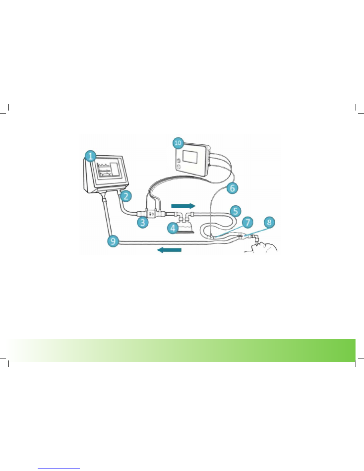
Conventional ventilator circuit
NOTE: To improve accuracy it is recommended to have up to 30cm between the patient Y-Piece (8) and the sample line (7).
1. Ventilator
2. Ventilator Inspiratory Port
3. NOxFLOW
TM
(use 22F or 15M to vent tube adaptors)
4. Humidifier
5. 0.7m-1.3m Corrugated Tubing (15mm or 22mm)
6. NOxBOX
i
Sample Line
7. 10M - 10F, 12M - 12F, 15M - 15M luer port or 22M-22F luer port connector
8. Patient Y-piece
9. Expiratory limb
10. NOxBOX
i
NOx
BOX
i
Operating Instructions
®
19
www.noxboxltd.com
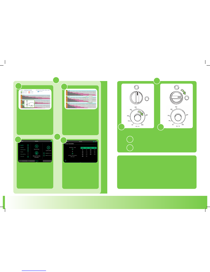
Manual override
NOTE: All dose information for the Manual Override are
approximations. Monitoring must be used to ensure the
patient is receiving the correct dose.
B
If Manual Override is required:
First check suitable flow rate is set.
Then engage mode selection valve to the
position seen on right hand side image.
2
A
A
B
B
Using on-screen
calculator access the
manual override
calculator from Settings.
Adjust vent flow to best match
patient settings. Table displays
approx. dose per valve setting.
Use the look-up tables in this
guide. To set flow rate, find the
table matching NO
supply concentration.
Find the vent flow setting to
best match patient settings.
The column lists the approx.
dose per valve setting.
A
A
B
To set flo
w r
at
es
1
OR
600
B
NOx
BOX
i
Operating Instructions
®
20
www.noxboxltd.com
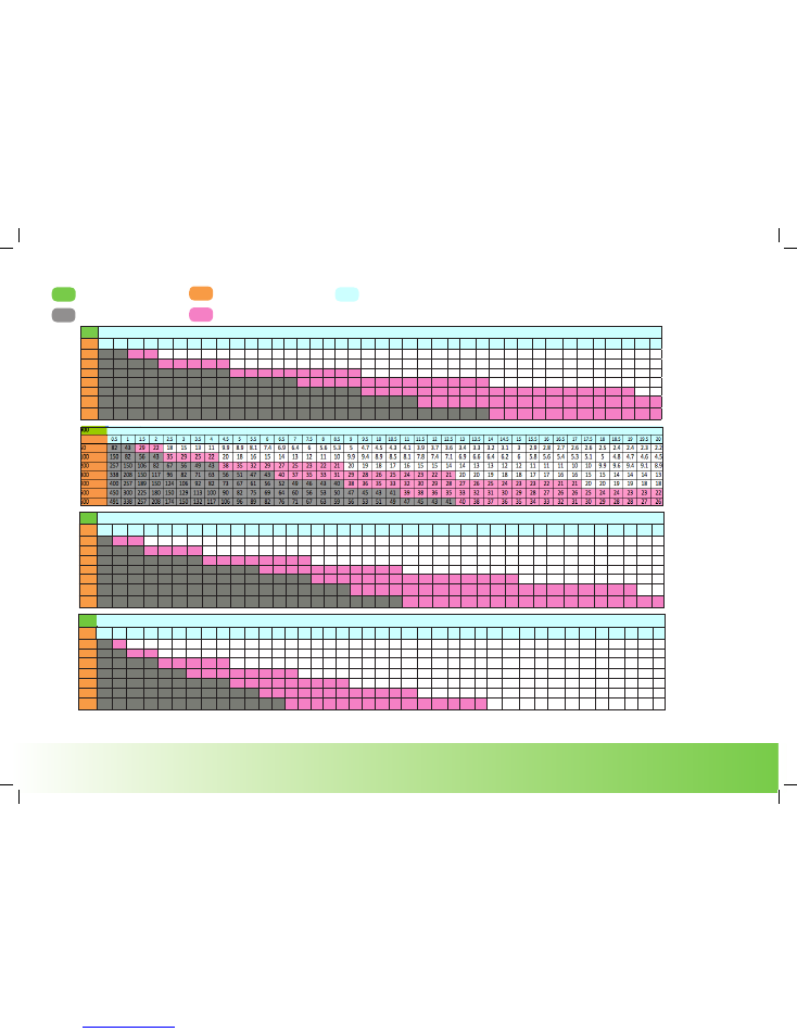
All dose information shown in these tables is for guidance only. The patient monitored gas levels should be used for actualy dose delivery information. All nitric oxide (NO) doses shown in parts per million
(ppm) when introduced to continuous flow rates indicated. Doses of NO above 40 ppm are not recommended. Doses above 20ppm are considered clinically high.
Flow valve setting
Minute flow volume
Clinder Concentration (ppm)
800
0.5
1
1.5
2
2.5
3
3.5
4
4.5
5
5.5
6
6.5
7
7.5
8
8.5
9
9.5
10
10.5
11
11.5
12
12.5
13
13.5
14
14.5
15
15.5
16
16.5
17
17.5
18
18.5
19
19.5
20
50
73
38
26
20
16
13
11
9.9
8.8
7.9
7.2
6.6
6.1
5.7
5.3
5
4.7
4.4
4.2
4
3.8
3.6
3.5
3.3
3.2
3.1
3
2.8
2.7
2.7
2.6
2.5
2.4
2.3
2.3
2.2
2.2
2.1
2
2
100
133
73
50
38
31
26
22
20
17
16
14
13
12
11
11
9.9
9.3
8.8
8.3
7.9
7.5
7.2
6.9
6.6
6.3
6.1
5.9
5.7
5.5
5.3
5.1
5
4.8
4.7
4.5
4.4
4.3
4.2
4.1
4
200
229
133
94
73
59
50
43
38
34
31
28
26
24
22
21
20
18
17
16
16
15
14
14
13
13
12
12
11
11
11
10
9.9
9.6
9.3
9
8.8
8.6
8.3
8.1
7.9
300
300
185
133
104
86
73
63
56
50
45
41
38
35
33
31
29
27
26
24
23
22
21
20
20
19
18
17
17
16
16
15
15
14
14
13
13
13
12
12
12
400
356
229
168
133
110
94
82
73
65
59
54
50
46
43
41
38
36
34
32
31
29
28
27
26
25
24
23
22
21
21
20
20
19
18
18
17
17
16
16
16
500
400
267
200
160
133
114
100
89
80
73
67
62
57
53
50
47
44
42
40
38
36
35
33
32
31
30
29
28
27
26
25
24
24
23
22
22
21
21
20
20
600
436
300
229
185
155
133
117
104
94
86
79
73
68
63
59
56
53
50
48
45
43
41
40
38
37
35
34
33
32
31
30
29
28
27
27
26
25
24
24
23
1000
0.5
1
1.5
2
2.5
3
3.5
4
4.5
5
5.5
6
6.5
7
7.5
8
8.5
9
9.5
10
10.5
11
11.5
12
12.5
13
13.5
14
14.5
15
15.5
16
16.5
17
17.5
18
18.5
19
19.5
20
50
91
48
32
24
20
16
14
12
11
9.9
9
8.3
7.6
7.1
6.6
6.2
5.8
5.5
5.2
5
4.7
4.5
4.3
4.1
4
3.8
3.7
3.6
3.4
3.3
3.2
3.1
3
2.9
2.8
2.8
2.7
2.6
2.6
2.5
100
167
91
63
48
38
32
28
24
22
20
18
16
15
14
13
12
12
11
10
9.9
9.4
9
8.6
8.3
7.9
7.6
7.4
7.1
6.8
6.6
6.4
6.2
26
5.8
5.7
5.5
5.4
5.2
5.1
5
200
286
167
118
91
74
63
54
48
43
38
35
32
30
28
26
24
23
22
21
20
19
18
17
16
16
15
15
14
14
13
13
12
12
12
11
11
11
10
10
9.9
300
375
231
167
130
107
91
79
70
63
57
52
48
44
41
38
36
34
32
31
29
28
27
25
24
23
23
22
21
20
20
19
18
18
17
17
16
16
16
15
15
400
444
286
211
167
138
118
103
91
82
74
68
63
58
54
51
48
45
43
40
38
37
35
34
32
31
30
29
28
27
26
25
24
24
23
22
22
21
21
20
20
500
500
333
250
200
167
143
125
111
100
91
83
77
71
67
63
59
56
53
50
48
45
43
42
40
38
37
36
34
33
32
31
30
29
29
28
27
26
26
25
24
600
545
375
286
231
194
167
146
130
118
107
98
91
85
79
74
70
66
63
59
57
54
52
50
48
46
44
43
41
40
38
37
36
35
34
33
32
31
31
30
29
WARNING: Dose >40 ppm
Dose over 20ppm
Minute Volume (L/Min)
Minute Volume (L/Min)
Dial
Dial
Minute Volume (L/Min)
Dial
500
0.5
1
1.5
2
2.5
3
3.5
4
4.5
5
5.5
6
6.5
7
7.5
8
8.5
9
9.5
10
10.5
11
11.5
12
12.5
13
13.5
14
14.5
15
15.5
16
16.5
17
17.5
18
18.5
19
19.5
20
50
45
24
16
12
9.8
8.2
7
6.2
5.5
5
4.5
4.1
3.8
3.5
3.3
3.1
2.9
2.8
2.6
2.5
2.4
2.3
2.2
2.1
2
1.9
1.8
1.8
1.7
1.7
1.6
1.6
1.5
1.5
1.4
1.4
1.3
1.3
1.3
1.2
100
83
45
31
24
19
16
14
12
11
9.8
8.9
8.2
7.6
7
6.6
6.2
5.8
5.5
5.2
5
4.7
4.5
4.3
4.1
4
3.8
3.7
3.5
3.4
3.3
3.2
3.1
3
2.9
2.8
2.8
2.7
2.6
2.6
2.5
200
143
83
59
45
37
31
27
24
21
19
18
16
15
14
13
12
11
11
10
9.8
9.3
8.9
8.5
8.2
7.9
7.6
7.3
7
6.8
6.6
6.4
6.2
6
5.8
5.6
5.5
5.3
5.2
5.1
5
300
188
115
83
65
54
45
39
35
31
28
26
24
22
21
19
18
17
16
15
15
14
13
13
12
12
11
11
10
10
9.8
9.5
9.2
8.9
8.7
8.4
8.2
8
7.8
7.6
7.4
400
222
143
105
83
69
59
51
45
41
37
34
31
29
27
25
24
22
21
20
19
18
18
17
16
16
15
14
14
13
13
13
12
12
11
11
11
11
10
10
9.8
500
250
167
125
100
83
71
63
56
50
45
42
38
36
33
31
29
28
26
25
24
23
22
21
20
19
19
18
17
17
16
16
15
15
14
14
14
13
13
13
12
600
273
188
143
115
97
83
73
65
59
54
49
45
42
39
37
35
33
31
30
28
27
26
25
24
23
22
21
21
20
19
19
18
18
17
17
16
16
15
15
15
Dial
Minute Volume (L/Min)
Dose look-up table
1000ppm, 900ppm, 800ppm, 500ppm
NOx
BOX
i
Operating Instructions
®
21
www.noxboxltd.com
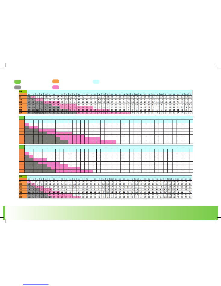
All dose information shown in these tables is for guidance only. The patient monitored gas levels should be used for actualy dose delivery information. All nitric oxide (NO) doses shown in parts per million
(ppm) when introduced to continuous flow rates indicated. Doses of NO above 40 ppm are not recommended. Doses above 20ppm are considered clinically high.
Flow valve setting
Minute flow volume
Clinder Concentration (ppm)
WARNING: Dose >40 ppm
Dose over 20ppm
Dose look-up table
450ppm, 400ppm , 300ppm, 250ppm
400
0.5
1
1.5
2
2.5
3
3.5
4
4.5
5
5.5
6
6.5
7
7.5
8
8.5
9
9.5
10
10.5
11
11.5
12
12.5
13
13.5
14
14.5
15
15.5
16
16.5
17
17.5
18
18.5
19
19.5
20
50
36
19
13
9.8
7.8
6.6
5.6
4.9
4.4
4
3.6
3.3
3.1
2.8
2.6
2.5
2.3
2.1
2.1
2
1.9
1.8
1.7
1.7
1.6
1.5
1.5
1.4
1.4
1.3
1.3
1.2
1.2
1.2
1.1
1.1
1.1
1
1
1
100
67
36
25
19
15
13
11
9.8
8.7
7.8
7.1
6.6
6.1
5.6
5.3
4.9
4.7
4.4
4.2
4
3.8
3.6
3.4
3.3
3.2
3.1
2.9
2.8
2.7
2.6
2.6
2.5
2.4
2.3
2.3
2.2
2.2
2.1
2
2
200
114
67
47
36
30
25
22
19
17
15
14
13
12
11
10
9.8
9.2
8.7
8.2
7.8
7.5
7.1
6.8
6.6
6.3
6.1
5.8
5.6
5.4
5.3
5.1
4.9
4.8
4.7
4.5
4.4
4.3
4.2
4.1
4
300
150
92
67
52
43
36
32
28
25
23
21
19
18
16
15
14
14
13
12
12
11
11
10
9.8
9.4
9
8.7
8.4
8.1
7.8
7.6
7.4
7.1
6.9
6.7
6.6
6.4
6.2
6.1
5.9
400
178
114
84
67
55
47
41
36
33
30
27
25
23
22
20
19
18
17
16
15
15
14
13
13
12
12
12
11
11
10
10
9.8
9.5
9.2
8.9
8.7
8.5
8.2
8
7.8
500
200
133
100
80
67
57
50
44
40
36
33
31
29
27
25
24
22
21
20
19
18
17
17
16
15
15
14
14
13
13
13
12
12
11
11
11
11
10
10
9.8
600
218
150
114
92
77
67
59
52
47
43
39
36
34
32
30
28
26
25
24
23
22
21
20
19
18
18
17
16
16
15
15
14
14
14
13
13
13
12
12
12
Minute Volume (L/Min)
Dial
Minute volume (L/Min)
Dial
300
0.5
1
1.5
2
2.5
3
3.5
4
4.5
5
5.5
6
6.5
7
7.5
8
8.5
9
9.5
10
10.5
11
11.5
12
12.5
13
13.5
14
14.5
15
15.5
16
16.5
17
17.5
18
18.5
19
19.5
20
50
27
14
9.7
7.3
5.9
4.9
4.2
3.7
3.3
3
2.7
2.5
2.3
2.1
2
1.9
1.8
1.7
1.6
1.5
1.4
1.4
1.3
1.2
1.2
1.1
1.1
1.1
1
1
1
0.9
0.9
0.9
0.8
0.8
0.8
0.8
0.8
0.7
100
50
27
19
14
12
9.7
8.3
7.3
6.5
5.9
5.4
4.9
4.5
4.2
3.9
3.7
3.5
3.3
3.1
3
2.8
2.7
2.6
2.5
2.4
2.3
2.2
2.1
2.1
2
1.9
1.9
1.8
1.8
1.7
1.7
1.6
1.6
1.5
1.5
200
86
50
35
27
22
19
16
14
13
12
11
9.7
9
8.3
7.8
7.3
6.9
6.5
6.2
5.9
5.6
5.4
5.1
4.9
4.7
4.5
4.4
4.2
4.1
3.9
3.8
3.7
3.6
3.5
3.4
3.3
3.2
3.1
3
3
300
113
69
50
39
32
27
24
21
19
17
16
14
13
12
12
11
10
9.7
9.2
8.7
8.3
8
7.6
7.3
7
6.8
6.5
6.3
6.1
5.9
5.7
5.5
5.4
5.2
5.1
4.9
4.8
4.7
4.5
4.4
400
133
86
63
50
41
35
31
27
24
22
20
19
17
16
15
14
13
13
12
12
11
11
10
9.7
9.3
9
8.6
8.3
8.1
7.8
7.5
7.3
7.1
6.9
6.7
6.5
6.3
6.2
6
5.9
500
150
100
75
60
50
43
38
33
30
27
25
23
21
20
19
18
17
16
15
14
14
13
13
12
12
11
11
10
10
9.7
9.4
9.1
8.8
8.6
8.3
8.1
7.9
7.7
7.5
7.3
600
164
113
86
69
58
50
44
39
35
32
30
27
25
24
22
21
20
19
18
17
16
16
15
14
14
13
13
12
12
12
11
11
11
10
9.9
9.7
9.4
9.2
9
8.7
Minute Volume (L/Min)
Minute Volume L/Min)
Dial
Dial
NOx
BOX
i
Operating Instructions
®
22
www.noxboxltd.com
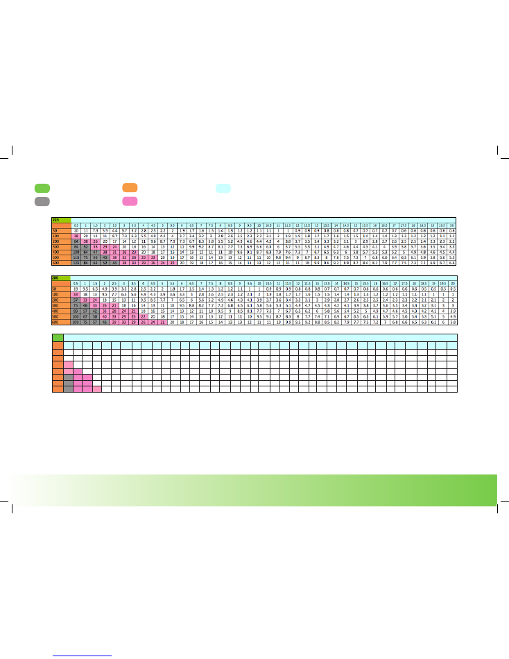
All dose information shown in these tables is for guidance only. The patient monitored gas levels should be used for actualy dose delivery information. All nitric oxide (NO) doses shown in parts per million
(ppm) when introduced to continuous flow rates indicated. Doses of NO above 40 ppm are not recommended. Doses above 20ppm are considered clinically high.
Minute Volume (L/Min)
Minute Volume (L/Min)
Dose look-up table
225ppm, 200ppm, 100ppm
Dial
Dial
Flow valve setting
Minute flow volume
Clinder Concentration (ppm)
WARNING: Dose >40 ppm
Dose over 20ppm
100
0.5
1
1.5
2
2.5
3
3.5
4
4.5
5
5.5
6
6.5
7
7.5
8
8.5
9
9.5
10
10.5
11
11.5
12
12.5
13
13.5
14
14.5
15
15.5
16
16.5
17
17.5
18
18.5
19
19.5
20
50
9.1
4.8
3.2
2.4
2
1.6
1.4
1.2
1.1
1
0.9
0.8
0.8
0.7
0.7
0.6
0.6
0.6
0.5
0.5
0.5
0.5
0.4
0.4
0.4
0.4
0.4
0.3
0.3
0.3
0.3
0.3
0.3
0.3
0.3
0.3
0.3
0.3
0.3
0.2
100
17
9.1
6.3
4.8
3.8
3.2
2.8
2.4
2.2
2
1.8
1.6
1.5
1.4
1.3
1.2
1.2
1.1
1
1
0.9
0.9
0.9
0.8
0.8
0.8
0.7
0.7
0.7
0.7
0.6
0.6
0.6
0.6
0.6
0.6
0.3
0.3
0.3
0.3
200
29
17
12
9.1
7.4
6.3
5.4
4.8
4.3
3.8
3.5
3.2
3
2.8
2.6
2.4
2.3
2.2
2.1
2
1.9
1.8
1.7
1.6
1.6
1.5
1.5
1.4
1.4
1.3
1.3
1.2
1.2
1.2
1.1
1.1
1.1
1
1
1
300
38
23
17
13
11
9.1
7.9
7
6.3
5.7
5.2
4.8
4.4
4.1
3.8
3.6
3.4
3.2
3.1
2.9
2.8
2.7
2.5
2.4
2.3
2.3
2.2
2.1
2
2
1.9
1.8
1.8
1.7
1.7
1.6
1.6
1.6
1.5
1.5
400
44
29
21
17
14
12
10
9.1
8.2
7.4
6.8
6.3
5.8
5.4
5.1
4.8
4.5
4.3
4
3.8
3.7
3.5
3.4
3.2
3.1
3
2.9
2.8
2.7
2.6
2.5
2.4
2.4
2.3
2.2
2.2
2.1
2.1
2
2
500
50
33
25
20
17
14
13
11
10
9.1
8.3
7.7
7.1
6.7
6.3
5.9
5.6
5.3
5
4.8
4.5
4.3
4.2
4
3.8
3.7
3.6
3.4
3.3
3.2
3.1
3
2.9
2.9
2.8
2.7
2.6
2.6
2.5
2.4
600
55
38
29
23
19
17
15
13
12
11
9.8
9.1
8.5
7.9
7.4
7
6.6
6.3
5.9
5.7
5.4
5.2
5
4.8
4.6
4.4
4.3
4.1
4
3.8
3.7
3.6
3.5
3.4
3.3
3.2
3.1
3.1
2
2.9
Minute Volume (L/Min)
Dial