Full Text Searchable PDF User Manual
We reserve the right to modify the characteristics of the equipment supplied without notice or as part of the continued development of our products.
0

We reserve the right to modify the characteristics of the equipment supplied without notice or as part of the continued development of our products.
1
DOMESTIC HOT WATER EFFICIENCY
Volume drawn
at 40
o
C in 10
minutes
Volume
drawn at
40
o
C in 1
hour
Heat
output
at
∆
T
30
o
K
Continuous
flow rate at 40
o
C
Specific flow
rate
(*1)
Pre-heating
time at 60
o
C
(*2)
Load time
at 60
o
C
Storage 65
o
C
Models
kW l/min
l/min
min min litres litres
THI 0.9-9 C +BS 100
9.1
4.4
14.2
29
51
160
377
THI 0.9-9 C +BS 150
9.1
4.4
20.2
43
77
241
459
THI 0.9-9 C +BS 200
9.1
4.4
25.6
56
100
313
531
THI 0.9-9 C +BS 300
9.1
4.4
37.7
86
153
476
693
THI 2-13 C +BS 100
13.5
6.5
15.2
19
35
160
483
THI 2-13 C +BS 150
13.5
6.5
21.3
29
52
241
564
THI 2-13 C +BS 200
13.5
6.5
26.7
38
68
313
636
THI 2-13 C +BS 300
13.5
6.5
38.8
58
103
476
798
THI 5-25 C +BS 100
23.9
11.4
17.6
11
19
176
748
THI 5-25 C +BS 150
23.9
11.4
23.9
17
29
241
813
THI 5-25 C +BS 200
23.9
11.4
29.3
21
38
313
885
THI 5-25 C +BS 300
23.9
11.4
29.3
33
58
476
1047
THI 10-50 C +BS 100
35.0
16.7
22.9
7
13
229
1067
THI 10-50 C +BS 150
35.0
16.7
26.1
11
20
261
1098
THI 10-50 C +BS 200
48.7
23.3
35.4
11
19
354
1519
THI 10-50 C +BS 300
48.7
23.3
47.5
16
29
476
1641
Cold water temperature = 10
o
C
(*2): Pre-heating time following drawing that
corresponds to the specific flow rate
(*1): According to EN 625

We reserve the right to modify the characteristics of the equipment supplied without notice or as part of the continued development of our products.
2
ELECTRICAL CONNECTIONS
FOR EBS RANGE OF CYLINDERS
Please Note
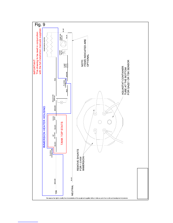
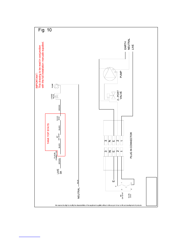
The Electrical “Straight Line” wiring diagram supplied with this literature is intended to assist in the
understanding of how the system works for fault finding and general assistance on the EBS cylinder, it
has no knowledge of individual peripherals fitted to the beginning or the end of the line, it does not
provide information on your chosen peripherals. Please refer to the manufacturer’s literature supplied
with each item you choose to install or please contact the Geminox-UK Technical helpline for further
assistance on + 44 (0)1372 722277.
Index
Page
2 Index
3
WRc approved documentation *
Contains important information, please read*
6
*Important notice, please read*
7
Hydraulic connections for cylinders
9
Cylinders with immersion heaters
11
Cylinders without immersion heaters
Figures
7
Fig 1 ¾” Unvented kit for EBS cylinder
7
Fig 2 ¾” Unvented kit for EBS cylinder
8
Fig 3 1” Unvented kit for EBS cylinder
8
Fig 4 1” Unvented kit for EBS cylinder
10
Fig 5 ¾” Safety zone valve
10
Fig 6 1” Safety zone valve
13
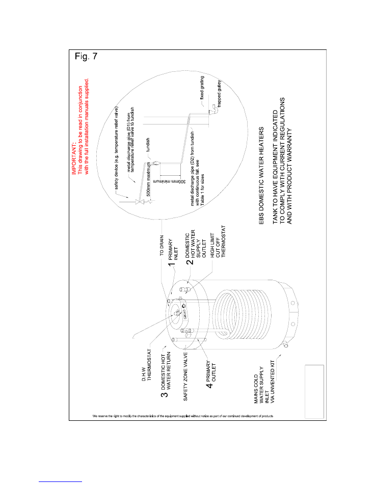
Fig 7 Requirements for EBS domestic unvented hot water cylinder
14
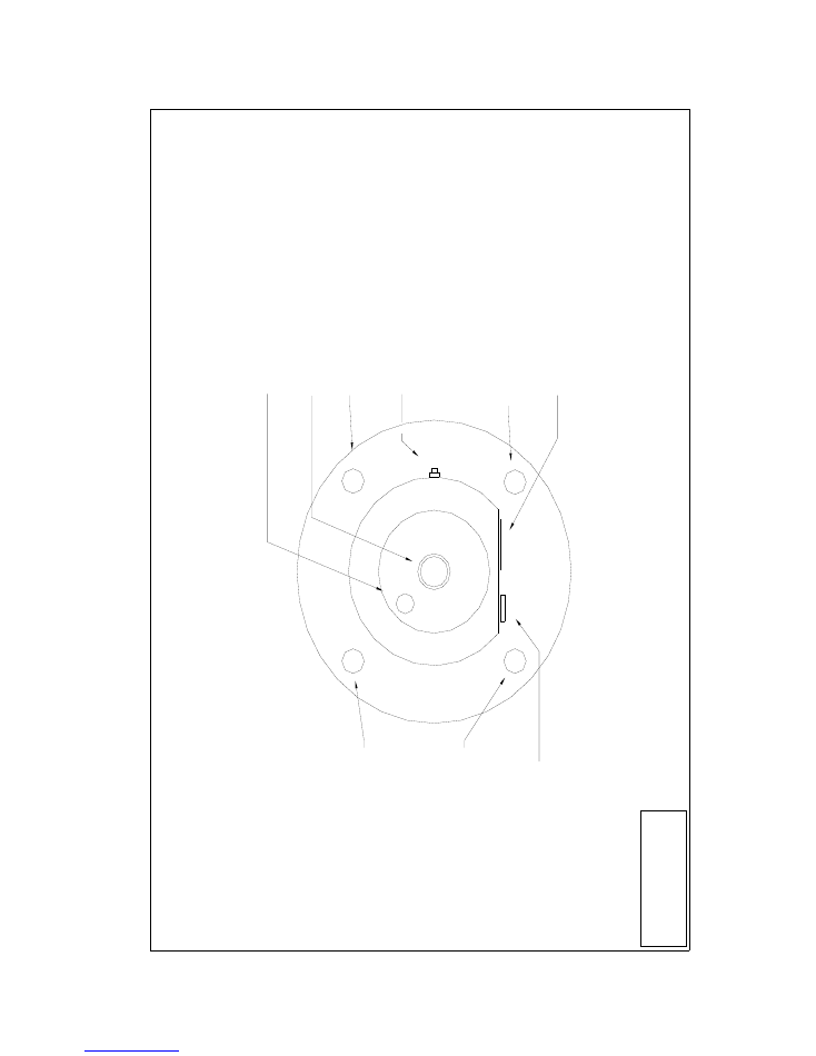
Fig 8 EBS cylinder sensor
15
Fig 9 Cylinder with immersion heater
16
Fig 10 Cylinder without immersion heater
17
Fig 11
Heating immersion set
18
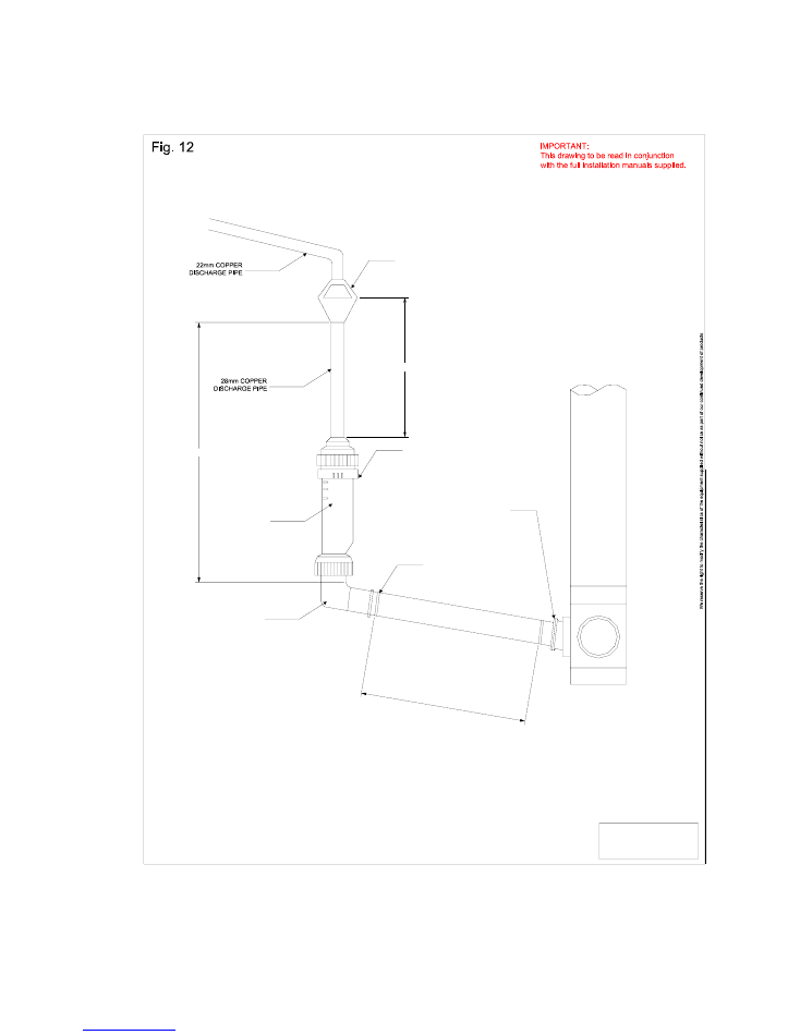
Fig 12 Discharge pipe arrangement using Hepworth Hep vO valve
Please ensure that prior to starting any Electrical work the cylinder has been isolated from the
mains supply. Where possible, lock off and warning signs to be posted.
Only Qualified Electricians should carry out the work necessary.

We reserve the right to modify the characteristics of the equipment supplied without notice or as part of the continued development of our products.
3
EBS WRc APPROVAL AMENDMENT TO MANUAL
WRc Approval No : 0210132
**NOTE TO INSTALLER** :
Please read fully prior to commencing installation. Leave manual with householder after
installation.
1 TECHNICAL
INFORMATION
Table 1
MODEL
EBS 100
EBS 150
EBS 200
EBS 300
Operating Pressure
3.5 Bar
3.5 Bar
3.5 Bar
3.5 Bar
Max Water Supply Pressure
12 Bar
12 Bar
12 Bar
12 Bar
Exp Relief Valve Setting
6 Bar
6 Bar
6 Bar
6 Bar
Nominal Storage Capacity
100 litres
150 litres
200 litres
300 litres
Pressure & Temperature Relief Valve
7 Bar/90
o
C 7
Bar/90
o
C 7
Bar/90
o
C 7
Bar/90
o
C
Expansion Vessel Charge Pressure
3.5 Bar
3.5 Bar
3.5 Bar
3.5 Bar
Weight without water
35 kg
45 kg
55 kg
70 kg
CONNECTIONS
Cold Water Inlet
¾”
¾”
¾”
¾”
Domestic Hot Water Flow
¾”
¾”
¾”
¾”
Hot Water Secondary Returns
¾”
¾”
¾”
¾”
Primary Flow from Boiler
¾”
¾”
¾”
¾”
Primary Return to Boiler
¾”
¾”
¾”
¾”
2 MAINTENANCE
WARNING :
BEFORE COMMENCING ANY MAINTENANCE WORK, ISOLATE ALL MAINS
ELECTRICITY SUPPLIES TO THE SYSTEM
The Cylinder and Cold Water Supply Kit should be inspected annually.
•
Close mains supply cock.
•
Drain down hot water system including the cylinder. (Use drain cock and/or the expansion relief
valve).
•
Check pressure in expansion vessel(s) and recharge to 3.5 Bar, if necessary.
•
Remove filter in line strainer. Clean or replace. Re-assemble. Refill system.
•
Check all pipework for leaks.
•
Open P & T valve and check that it discharges water.
•
Open expansion relief valve and check that it discharges water.
•
Check operation of all controls.
Every two years, the following additional maintenance should also be carried out after draining
down.
•
Remove Electric Immersion Heater cover (if fitted).
•
Disconnect wiring to Immersion Heater Boss (if fitted).

We reserve the right to modify the characteristics of the equipment supplied without notice or as part of the continued development of our products.
4
•
Undo securing nuts on heater flange and remove flange complete with Electric Immersion
Heater.
•
Inspect heater elements and de-scale if necessary.
•
Inspect interior of cylinder and clean out any debris.
•
Re-assemble using a new gasket on the flange and tighten bolts.
•
Re-connect Immersion Heater wiring.
•
Refill system and check for leaks around flange.
•
Replace Electric Immersion Heater cover.
•
Carry out annual inspection as above.
3
THE OPENING TEMPERATURE OF THE P & T VALVE IS 90
o
C
The position of the tundish shall be visible to the occupants and shall be positioned away from
any electrical devices.
See Fig no. 7, Page 13 of EBS manual for tundish position and discharge pipe.
The connection details are shown on Page 13, drawing no. Fig 7. The relief valve connections
should not be altered or used for any other type of connection.
Details of the discharge pipe and installation requirements can be seen on drawing no. Fig 7,
Page 13 and Table 2, Page 6.
Before connecting pipework, fit the Siemens safety shut off zone valve to the primary return
outlet.
The incoming cold water supply pipe must be fitted with a stopcock before the cold water
unvented kit. A drain cock must be fitted between the unvented kit and the cylinder.
The unit should be carried into position within its packaging and on its pallet.
Once in position, the pallet should be removed.
The cylinder should be installed on a floor designed to take the weight of the cylinder when full
of water. Each litre of water weighs 1 Kg. The actual water content of each cylinder should
be added to the cylinder weight to obtain the total weight of the cylinder when full to ascertain
if the floor is of suitable construction.
300mm clearance should be left on the top of the cylinder for access to the anode and
inspection door.
No valve shall be fitted between the cylinder and the expansion valve.
Our optional immersion heater control panel is unique in that you cannot heat the water using
the boiler and the immersion on at the same time. The rocker switch on the control panel
either sends power to the immersion heater or to the boiler safety circuit. So, if the immersion
is on, the valve closes and the boiler cannot supply hot water to the cylinder.
No other immersion, other than our EBS Immersion Heater should be used on our EBS
cylinders.
The EBS range of cylinders is ideally suited for connection to our Geminox boilers to match
the coil ratings. However, connection to non – Geminox boilers can be carried out if required.
Please contact our Technical Department for installation assistance on + 44 (0)1372 722277.
To flush through the cylinder, simply open inspection door, disconnect unvented kit and flush
through the cylinder to the drain by using a hose through the inspection door.
100
300
Results of supply temperature 1-50 – 220
19 mins
26 mins

We reserve the right to modify the characteristics of the equipment supplied without notice or as part of the continued development of our products.
5
Results of the reheat time 1-50 – 222
13 mins
16 mins
•
This unit is only to be used with our oil or gas boiler with a thermostatic control. It should not
be used with a solid fuel appliance.
•
Please note that if a secondary circuit is used then an additional expansion vessel may be
required.
•
In hard water areas you should not exceed 60
o
C as a store temperature.
4 COMMISSIONING
•
Check all pipe connections for tightness. Close drain cock.
•
Check pressure(s) in expansion vessel(s) 3.5 Bar. Recharge if necessary.
•
Fill primary circuits, vent and check for leaks.
•
Chock open P & T valve on top of cylinder (by fitting manual lever).
•
Open stopcock and fill cylinder with water until if freely discharges through the outlet
from the P &T valve.
•
Remove chock and close P & T valve.
•
Test delivery of water from cylinder by opening and running all taps, both hot and cold
water and any other water discharge points (showers etc).
•
Check operation of expansion relief valve on Cold Water Supply Kit by lifting manual
release lever and discharging water.
•
Check all pipework and connections for leaks.
5
HEATING OF TANK FROM BOILER
•
Check any programmers are calling for HOT WATER. Set hot water thermostat on
tank to Maximum. Run heating boiler until the temperature gauge on the cylinder
indicates approximately 50
o
C.
•
Turn down the hot water thermostat and check that motorised valve closes and
loading pump stops.
•
Check that the boiler shuts down. If the boiler is also feeding a heating circuit, make
sure that there is NO demand from the heating circuit (Room Stat, Programmer, Zone
Valve etc).
6
HEATING OF TANK FROM ELECTRIC IMMERSION HEATER
•
Switch on the power supply to the Electric Immersion Heater.
•
Turn Electric Heater thermostat up and down to check that heater is turning on and off
correctly.
•
Select the desired hot water temperature.
The total fuse rating for the immersion heater is 13.04A, a suitable protective device should be
selected. The boiler should be protected by a fused spur with a cartridge fuse of no higher
than 3A.

We reserve the right to modify the characteristics of the equipment supplied without notice or as part of the continued development of our products.
6
Please Note
The Geminox range of products are designed to be used in installations where the complete system is
supplied by Geminox therefore when used in conjunction with other products some slight alterations to
the Electrical installation may have to be made.
Important Notice
When the system installed is “Unvented” controlling the Zone valve by way of the cylinder and
overheat thermostats, follow the steps on page 4, in this instance the zone valve is called the “Safety
shut off zone valve”, the valve is supplied with the Unvented Kit and must be installed.
The safety shut off zone valve is an important safety device of the unvented EBS tank and must
be installed. Fit the valve to the return connection of the tank connection, No. 4. The valve is
to be controlled via terminal L2 of the immersion plug or if no immersion is fitted, terminal T1
of the tank top cable plug. Please find in attached photos and fig. 11 how to connect the
“Safety shut off zone valve”.
Safety Discharge Pipe from Tundish
See Table 2 below for sizing details of safety discharge pipe from our tundish.
Table 2
Sizing of copper discharge pipe D2 for common temperature relief valve outlet sizes
Valve Outlet Size
Minimum
Size
of
Discharge Pipe
D1
Minimum Size of
Discharge Pipe
D2 from tundish
Maximum resistant
allowed, expressed as a
length of straight pipe
(ie. no elbows or bends)
Resistance created
by each elbow or
bend
G ½
15mm
22mm
28mm
35mm
Up to 9m
Up to 18m
Up to 27m
0.8m
1.0m
1.4m
G ¾
22mm
28mm
35mm
42mm
Up to 9m
Up to 18m
Up to 27m
1.0
1.4m
1.7m
Worked Example :
The example below is for a G ½ temperature relief valve with a discharge pipe (D2) having 4 no.
elbows and length of 7m from the tundish to the point of discharge.
From Table 2
Maximum resistance allowed for a straight length or 22mm copper discharge pipe (D2) from a G ½
temperature relief valve is 9.0m.
Subtract the resistance for 4 no. 22mm elbows at 0.8m each = 3.2m
Therefore, the maximum permitted length equates to : 5.8m
5.8m is less than the actual length of 7m, therefore calculate the next largest size.
Maximum resistance allowed for a straight length of 28mm pipe (D2) from a G ½ temperature relief
valve equates to 18m
Subtract the resistance for 4 no. 28mm elbows at 1.0m each = 4m
Therefore the maximum permitted length equates to : 14m
As the actual length is 7m, a 28mm (D2) copper pipe will be satisfactory.
We reserve the right to modify the characteristics of the equipment supplied without notice or as part of the continued development of our products.
7
HYDRAULIC CONNECTIONS FOR CYLINDERS
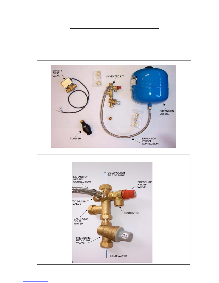
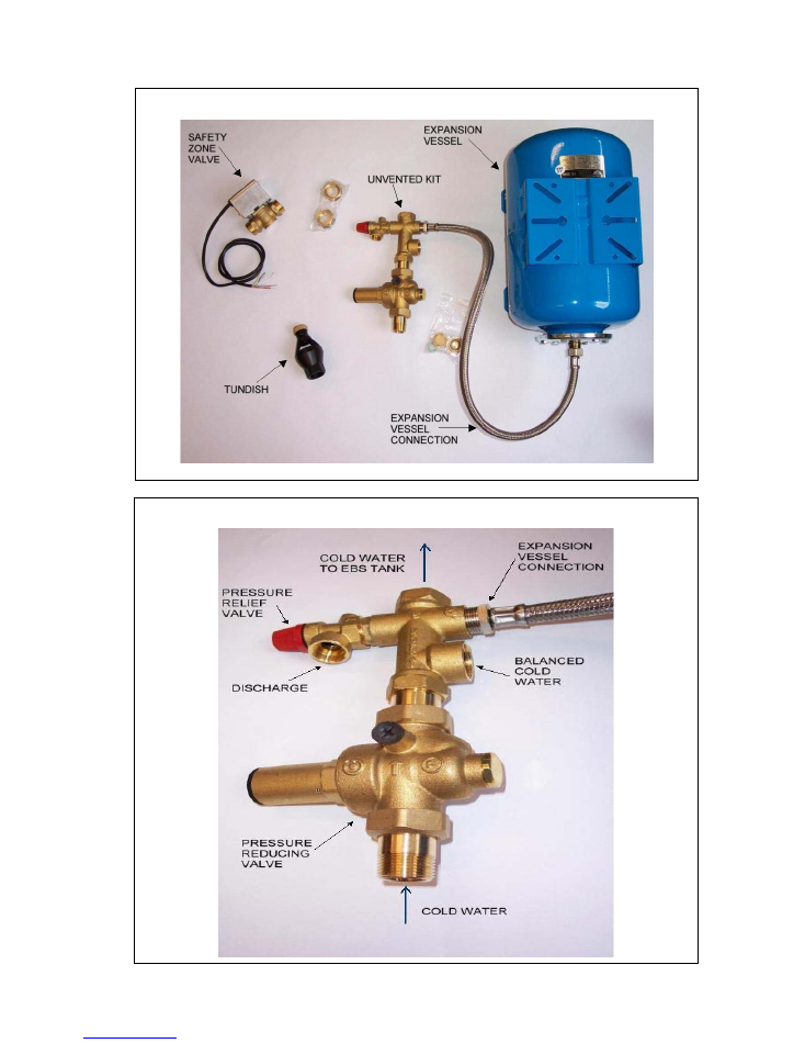
When the system installed is “Unvented” it is necessary to fit the “unvented kit” on the cold
water supply. The “Unvented kit” contains pressure reducing valve, non-return valve, pressure
relief valve and optional use balanced cold water connector. It is good practice to fit the
“unvented kit” above the top level of the EBS tank. In this way if it is required to replace the
“unvented kit” it is not necessary to drain all tank. Please find below how to install the
“unvented kit”
Fig. 1 ¾” Unvented kit for EBS cylinders
Fig. 2 ¾” Unvented kit for EBS cylinders
We reserve the right to modify the characteristics of the equipment supplied without notice or as part of the continued development of our products.
8
Fig. 3 1” Unvented kit for EBS cylinders
Fig. 4 1” Unvented kit for EBS cylinders
We reserve the right to modify the characteristics of the equipment supplied without notice or as part of the continued development of our products.
10
11
Whilst in heating cycle using the immersion heater the Green selector switch LED will
illuminate and extinguish once desired temperature is reached.
Fig. 5 ¾” Safety zone valve
Fig. 6 1” Safety zone valve

We reserve the right to modify the characteristics of the equipment supplied without notice or as part of the continued development of our products.
11
ELECTRICAL CONNECTIONS FOR CYLINDERS
WITHOUT IMMERSION
Please ensure the EBS cylinder has been installed and sited correctly in accordance with the
Geminox-UK instructions supplied with the equipment.
Step
1 Remove the Black connector plug from the rear of the cylinder temperature control housing on
the top of the cylinder.
2 Open the connector plug using a small flathead screwdriver inserted into the slots on the sides
of the connector plug.
3 Looking at the terminals inside the connector plug they are marked 1, 2, CPC, N and 3.
4 Line in to No2 and line out to No1, when No voltage present or phase to No2 and switch line
to No1, when voltage present.
5 In both cases the CPC must be supplied from a good and reliable source.
6 Terminate No. 1 to control the safety shut off zone valve as follows :
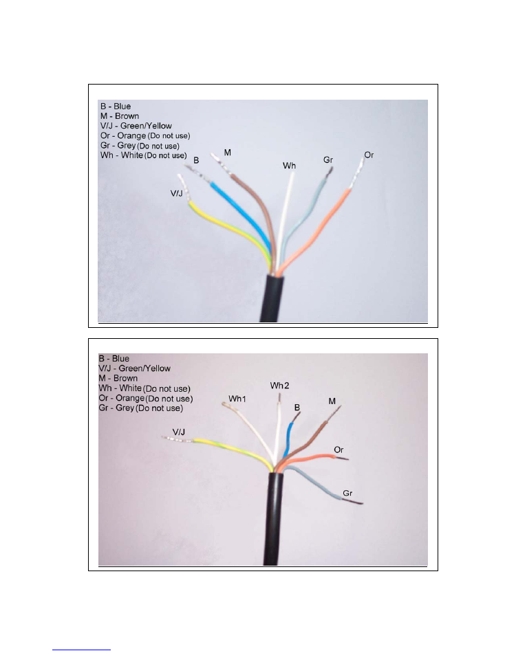
The safety shut off zone valve is wired as follows :
Brown
=
L2 (LIVE)
Blue
=
Neutral
Green/Yellow =
CPC
7 The desired temperature setting should now be set using the controls on the top of the
cylinder or should be left on maximum if the hot water is controlled via our boiler controls.
Technical note
The cylinder temperature control housing, on top of the cylinder, contains a high limit thermostat, an
adjustable thermostat, and a temperature sensor, none of which require voltage to operate, both
thermostats “Open” once the desired temperature is reached and break the circuit, the temperature
gauge phial displays the temperature on the front of the cylinder and the sensor will display the
temperature of the water inside the cylinder on the boiler controller.
Please Note
The Geminox range of products are designed to be used in installations where the complete system is
supplied by Geminox therefore when used in conjunction with other
non
-Geminox products some
slight alterations to the electrical installation may have to be made.
Important Notice
When the system installed is “Unvented” controlling the zone valve by way of the cylinder and
overheat thermostats, follow the steps on page 9. In this instance the zone valve is called the
“Safety shut off zone valve”. The valve is supplied with the unvented kit and must be installed.
We reserve the right to modify the characteristics of the equipment supplied without notice or as part of the continued development of our products.
13
PR
E
S
SU
R
E
&
TEM
P
ER
AT
URE
REL
IE
F
VAL
V
E
We reserve the right to modify the characteristics of the equipment supplied without notice or as part of the continued development of our products.
14
We reserve the right to modify the characteristics of the equipment supplied without notice as part of our continued development of products
IM
P
O
RTANT:
Thi
s drawing to be re
ad
in
conjun
cti
o
n
w
ith the
fu
ll in
stal
lation
manual
s
suppl
ied.
SE
C
O
N
D
AR
Y
RETURN ENTRY
POIN
TS
THER
MOST
AT
TEMPE
R
ATUR
E
CO
NTR
O
L
THER
MOSTAT
HO
LE
P
& T VALV
E
PRIM
ARY F
LOW
ENTR
Y POIN
TS
HIG
H
L
IMIT THER
MOS
T
A
T
R
ESETAB
LE
TEMPER
ATUR
E DI
SP
LAY
WIN
D
OW
HOT WATE
R
OU
T
LE
T
PR
IMAR
Y R
E
T
URN
Fig. 8
We reserve the right to modify the characteristics of the equipment supplied without notice or as part of the continued development of our products.
15
We reserve the right to modify the characteristics of the equipment supplied without notice or as part of the continued development of our products.
16
We reserve the right to modify the characteristics of the equipment supplied without notice or as part of the continued development of our products.
18
NOTE:
THIS DETAIL IS ONLY TO BE USED WHERE THERE
IS NO OTHER ALTERNATIVE. IT IS STRICTLY
SUBJECT TO LOCAL DISPENSATION AND
APPROVAL MUST BE SOUGHT FROM NHBC AND
BUILDING CONTROL INSPECTOR PRIOR TO
INSTALLATION
30
0 m
m
mi
ni
mu
m
fr
om
T
un
di
sh t
o
Bend
(
B
u
ild
ing
Reg
ulatio
ns
requ
irem
ents
)
2
00 mm min
imu
m hei
ght
ab
ov
e Hep
vO
Valv
e
300 mm betw
een pipe clips
PIPE CLIP TO BE POSITIONED
CLOSE TO VALVE TO PROVIDE
ADDITIONAL SUPPORT
WASTE TYPICALLY DISCHARGED
TO SOIL STACK THROUGH BOSS
ADAPTER
HepvO VALVE MUST BE VERTICAL
AND ADJACENT TO THE WATER
UNIT, TO BE VISIBLE & EASILY
ACCESSIBLE
TUNDISH - VISIBLE POINT OF
DISCHARGE
32mm
POLYPROPYLENE
WASTE PIPE
32mm HepvO
VALVE
SOIL STACK