Full Text Searchable PDF User Manual
SPLIT TYPE
ROOM AIR CONDITIONER
WALL MOUNTED TYPE
Indoor unit
Outdoor unit
ASU18RLF
ASU24RLF
AOU18RLXFW1
AOU24RLXFW1
C O N T E N T S
SPECIFICATIONS . . . . . . . . . . . . . . . . . . . .
1
DIMENSIONS. . . . . . . . . . . . . . . . . . . . . . . .
2
REFRIGERANT SYSTEM DIAGRAM . . . . .
4
CIRCUIT DIAGRAM. . . . . . . . . . . . . . . . . . .
5
ERROR DERECTION. . . . . . . . . . . . . . . . .
6
PCB CIRCUIT DIAGRAM . . . . . . . . . . . . . .
8
PARTS (INDOOR UNIT) . . . . . . . . . . . . . . .
9
PARTS (OUTDOOR UNIT) . . . . . . . . . . . .
15
19
ACCESSORIES. . . . . . . . . . . . . . . . . . . . .
SPECIFICATIONS
Type
Cool & heat inverter
Indoor unit
ASU18RLF
Outdoor unit
AOU18RLXFW1
Capacity
COOLING
Capacity
HEATING
Power supply
Operating current
Operating current
Max ope. current
Max ope. current
Power consumption
Power consumption
EER
COP
Dehumidification
FAN MOTOR AND FAN REVOLUTION
High
Indoor unit
Cooling
Medium
Low
Quiet
High
Indoor unit
Heating
Medium
Low
Quiet
Outdoor unit Heating
Outdoor unit Cooling
18,000 Btu/h
21,600 Btu/h
Single phase 208/230V 60Hz
6.2 A
7.8 A
1.35 kW
1.75 kW
13.3 Btu/hW
12.3 Btu/hW
541 CFM 920 m
3
/h
541 CFM 920 m
3
/h
13.5 A
14.5 A
ASU24RLF
AOU24RLXFW1
22,000 Btu/h
25,200 Btu/h
7.9 A
8.6 A
1.76 kW
1.94 kW
12.5 Btu/hW
13.0 Btu/hW
6.3 Pts/h 3.0 L/h
677 CFM 1,150 m
3
/h
435 CFM 740 m
3
/h
530 CFM 900 m
3
/h
365 CFM 620 m
3
/h
435 CFM 740 m
3
/h
318 CFM 540 m
3
/h
365 CFM 620 m
3
/h
1,489 CFM 2,530 m
3
/h
2,001 CFM 3,400 m
3
/h
1,489 CFM 2,530 m
3
/h
2,119 CFM 3,600 m
3
/h
659 CFM 1,120 m
3
/h
435 CFM 740 m
3
/h
530 CFM 900 m
3
/h
365 CFM 620 m
3
/h
435 CFM 740 m
3
/h
306 CFM 520 m
3
/h
365 CFM 620 m
3
/h
15.0 A
15.5 A
1,260 rpm
1,020 rpm
900 rpm
770 rpm
1,260 rpm
1,020 rpm
900 rpm
790 rpm
620 rpm
620 rpm
OU Discrimination
IU Discrimination
MFE-60TVT
MFD-50RON
1,480 rpm
1,220 rpm
1,020 rpm
900 rpm
1,430 rpm
1,220 rpm
1,020 rpm
900 rpm
850 rpm
800 rpm
ELECTRICAL DATA
2016.02.10
1
High
Medium
Low
Quiet
Indoor unit
Cooling
High
Medium
Low
Quiet
Indoor unit
Heating
Outdoor unit Heating
NOISE LEVEL
Outdoor unit Cooling
43 dB
37 dB
33 dB
28 dB
44 dB
37 dB
33 dB
28 dB
50 dB
47 dB
49 dB
42 dB
37 dB
33 dB
49 dB
42 dB
37 dB
33 dB
55 dB
54 dB
Compressor type
Hermetic type, 6 pole, 3 phase,
DC inverter motor, Rotary
Discrimination
Precharged refrigerant
Refrigerant type
R410A
Weight (with oil)
COMPRESSOR AND REFRIGERANT
pipe length
66 ft. 20 m
Full
charge
164 ft. 50 m
Maximum piping height
98 feet 30 m
Additional charge
0.43 oz/ft 40 g/m
WEIGHT
IU
Net / Shipping
Net / Shipping
OU
Indoor unit
H x W x D
H x W x D
Outdoor unit
135 lbs / 150 lbs 61 kg / 68 kg
DIMENSIONS
AIR CIRCULATION
High
Indoor unit
Cooling
Medium
Low
Quiet
High
Indoor unit
Heating
Medium
Low
Quiet
Outdoor unit Heating
Outdoor unit Cooling
12-5/8 x 39-1/4 x 9 inch
320 x 998 x 228 mm
31 lbs / 40 lbs 14 kg / 18 kg
32-3/4 x 35-3/8 x 13 inch
830 x 900 x 330 mm
5.9 Pts/h 2.8 L/h
N-TF30ND1A
4 lbs 10 oz 2,100 g
34.2 lbs 15.3 kg
4 lbs 10 oz 2,100 g
98 ft. 30 m
5 lbs 8 oz 2,500 g
131 ft. 40 m
6 lbs 6 oz 2,900 g
7 lbs 4 oz 3,300 g
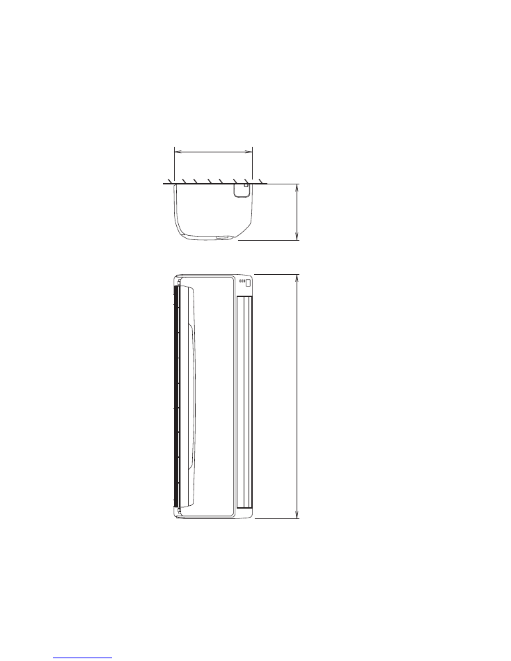
DIMENSIONS
Unit : inch (mm)
Drain pipe diameter
Inside : 5/8 inch (16 mm)
Outside : 1-3/32 inch (28 mm)
Liquid pipe diameter : 3/8 inch (9.52 mm)
Gas pipe diameter : 5/8 inch (15.88 mm)
INDOOR UNIT
39-1/4" (998)
9" (228)
12-5/8"
(320)
2010.02.26
2
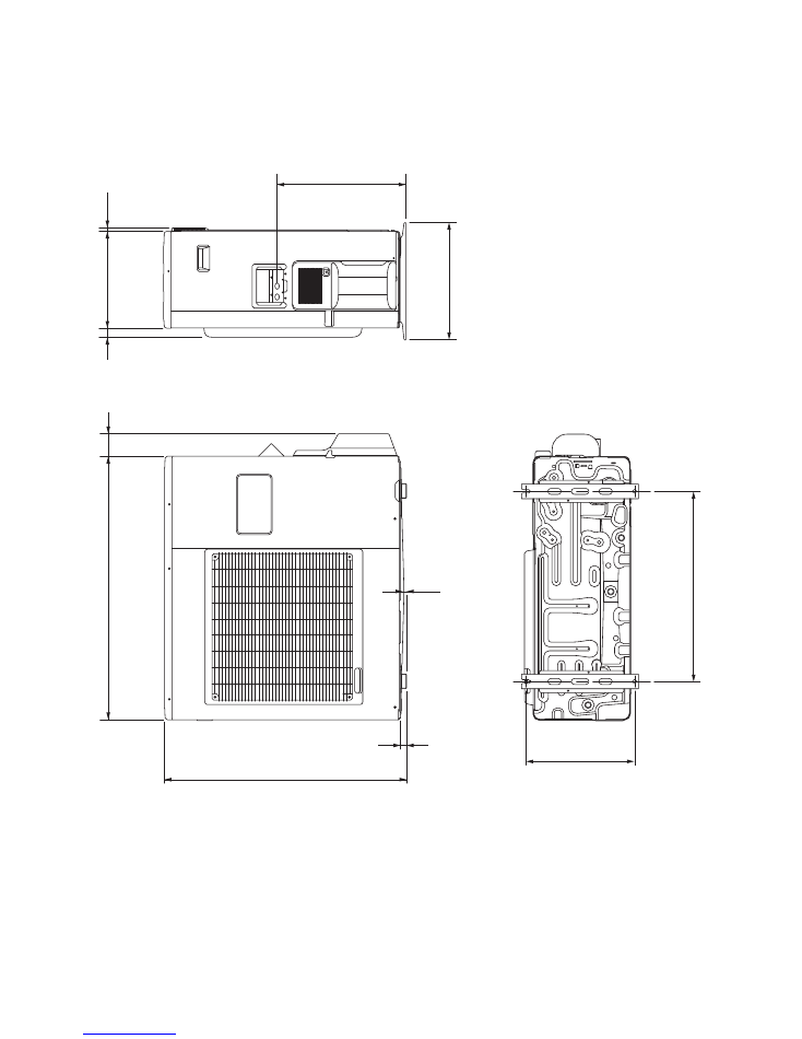
Unit : inch (mm)
OUTDOOR UNIT
3"(77)
35-1/2" (900)
32-3/4" (830)
17-3/8" (440)
7/8"
(21)
3/8"
(9)
15-3/4" (400)
13" (330)
1-1/4"
(31)
1/2"
(12)
14-5/8" (370)
25-5/8" (650)
2010.02.26
3
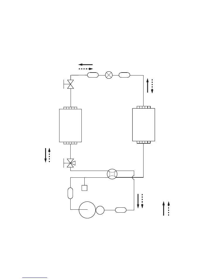
REFRIGERANT
SYSTEM DIAGRAM
3-Way valve
(Small)
3-Way valve
(Large)
Strainer
Strainer
Muffler
Pressure
switch
4-Way valve
Expansion
valve
Heat exchanger
( INDOOR )
Heat exchanger
( OUTDOOR )
Sub-accumulator
Compressor
Refrigerant pipe diameter
Liquid : 3/8" (9.52 mm)
Gas : 5/8" (15.88 mm)
Cooling flow
Heating flow
2010.02.26
4
7
6
5
4
3
2
1
7
6
5
4
3
2
1
7
6
5
4
3
2
1
5
4
3
2
1
3
2
1
3
2
1
2
1
2
1
2
1
3
2
1
5
4
3
2
1
5
4
3
2
1
6
5
4
3
2
1
6
5
4
3
2
1
6
5
4
3
2
1
6
5
4
3
2
1
5
4
3
2
1
1
2
3
4
5
6
1
2
3
4
5
6
CN13
CN16
CN14
CN10
CN3
CN1
CN8
CN6
CN5
CN11
CN2
TM1
TM4
T
M2
W5
CN201
Blue
Y
e
llow
White
Black
Red
Blue
Pink
Y
e
llow
Orange
Red
Blue
Pink
Y
e
llow
Orange
Red
Blue
Pink
Y
e
llow
Orange
Red
Green
White
Red
Black
Black
Black
Black
White
White
White
White
White
White
Red
Black
White
Red
FM
Te
s
t
Fan motor
M
Dif
fuser
M
Louver ( Up / Down )
M
Louver ( Right / Left )
G
1
23
T
e
rminal
Ex. out
( Option )
Ex. in
( Option )
Thermistor ( Pipe temp. )
Thermistor ( Room temp. )
Wired remote control
( Option )
Indicator PCB
Thermal
fuse 102
Main PCB
RED
RED
Brown
Brown
Blue
Blue
Black
Black
Brown
Brown
Black
Black
White
Y
ellow
Orange
Blue
Red
Brown
Y
ellow
White
Black
Red
Red
Green
White
Black
White
Black
V
iolet
White
Blue
Y
ellow
Black
Red
Brown
Orange
Orange
Orange
Red
White
Black
White
White
Black
White
1
2
Gray
or White
Black
White
Black
White
White
White
White
White
White
White
White
White
White
White
White
White
White
White
Black
Brown
Red
Orange
Yellow
1
2
3
4
5
6
7
8
9
1
2
3
4
5
6
7
8
9
1
2
3
4
5
1
2
3
4
5
9
8
7
6
5
4
3
2
1
5
4
3
2
1
9
8
7
6
5
4
3
2
1
5
4
3
2
1
1
2
1
2
1
2
3
4
1
2
3
4
1
2
3
4
5
6
1
2
3
4
5
6
1
2
1
2
1
2
1
2
1
2
3
4
5
6
7
CN1
1
2
3
4
5
6
7
1
2
3
4
5
1
2
3
4
5
1
2
1
2
1
2
3
1
2
3
1
2
3
1
2
3
1
2
3
1
2
3
1
2
3
1
2
3
1
2
1
2
CN1
10
TM600
TM601
CN100
CN800
W4
W29
W28
W25
W26
W21
W9
W20
W19
W3
W18 W17
W2
W1
CN700
CN500
CN63
CN65
CN62
CN64
CN90
CN1
1
N
P
L2
L1
-
I N
+I N
W8
W7
W13
W12
CN400
CN200
CN40
CN42
CN303
CN301
W306
W307
TM102
TM101
W16
W17
TM301
TM302
TM303
W
TM305
U
TM304
V
S
T
R
CM
Compressor
Posistor
Choke coil
T
e
rminal
G
G
L2
L1
3
2
1
PMV
FM
4WV
Fan motor
Expansion valve coil
4-way valve coil
Thermistor ( Discharge pipe )
Thermistor ( Pipe temp. )
Thermistor ( Outdoor temp. )
Thermistor ( Compressor temp. )
High pressure switch
ACTPM
Capacitor PCB
T
ransistor PCB
( I P
M )
Filter PCB
Main PCB
Power source
O
U
T
D
O
O
R
U
N
IT
IN
D
O
O
R
U
N
IT
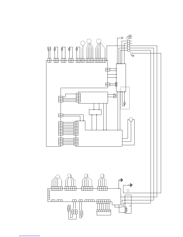
C
IR
C
U
IT
D
IA
G
R
A
M
2016.02.10
5
AOU24RLXFW1 Only
UL1061
A
WG28 x 7
CN1
1
-1
RED
CN1
1
-2
WHITE
CN1
1
-3
WHITE
CN1
1
-4
WHITE
CN1
1
-5
WHITE
CN1
1
-6
WHITE
CN1
1
-7
WHITE
UL1007
A
W
G26 x 2
CN2-1
BLACK
CN2-2
BLACK
CN3-1
CN3-2
RED
WHITE
BLACK
BLACK
CN13-1
CN13-2
CN13-4
CN13-3
CN13-5
UL1061
A
WG26 x 5
UL1061
A
WG26 x 5
UL1061
A
WG26 x 5
UL3266
A
WG22 x 5
UL1061
A
WG26 x 3
CN5-1
RED
CN5-2
ORANGE
CN5-3
YELLOW
CN5-4
PINK
CN5-5
BLUE
CN10-6
RED
CN8-1
RED
CN8-2
ORANGE
CN8-3
YELLOW
CN8-4
PINK
CN8-5
BLUE
CN10-4
BLACK
CN10-3
WHITE
CN10-2
YELLOW
CN10-1
BLUE
CN2-3
YELLOW
CN2-1
RED
CN2-2
ORANGE
CN2-4
PINK
CN2-5
BLUE
CN6-1
RED
CN6-2
WHITE
CN6-3
BLACK
UL1015
A
WG24
BLACK
UL1015
A
WG24
WHITE
UL1015
A
WG24
RED
L
N
SERIAL
E
1
2
3
M
M
M
F M
DC F
A
N MOT
O
R
DIFFUSER
LOUVER ( UP
/ DOWN )
LOUVER ( RIGHT
/ LEFT
)
THERMIST
OR ( ROOM
TEMP
. )
THERMIST
OR ( PIPE
TEMP
. )
XARR
-03VF
XAP
-03V
-1
EX. OUT
EX. I N
CN201
07 JB20/P
A
P
1061 L230
WHITE
1
2
3
4
5
6
7
1
2
3
4
5
6
7
1
2
3
4
5
6
7
1
2
3
1
2
1
2
1
2
1
2
3
4
5
1
2
3
4
5
1
2
3
4
5
1
2
3
4
5
6
1
2
3
4
5
6
6
5
4
3
2
1
CN1
1
B07B-P
ASK-1
WHITE
CN14
B3B-XH-AM
WHITE
CN16
B2B-XH-AM
WHITE
CN3
02/03 JC25/XARR
1007 L60
WHITE
CN1
150-103-86172
WHITE
CN13
B5B-PH-K-S
WHITE
TEST
FLASH
CN9
B07B-P
ASK-1
WHITE
CN6
B05B-XASK-1-A
WHITE
CN2
SJH20-05WS
WHITE
CN5
SJH20-06WS
WHITE
CN8
B06B-P
ASK-1
WHITE
CN10
B5 ( 6-5 ) B-XARK-1-A
RED
TERMINAL
HP-T3064A-A29-L1
E
W5
GREEN
EAR
T
H
TM2
22007
RED
SERIAL
I N
TM1
22007
WHITE
N I N
TM4
22007
BLACK
L
I N
INDICA
T
O
R PCB
K05CY
-0902HSE-D0
WIRED REMOTE CONTROL
( OPTION )
POWER SOURCE
AC208 - 230V
60Hz
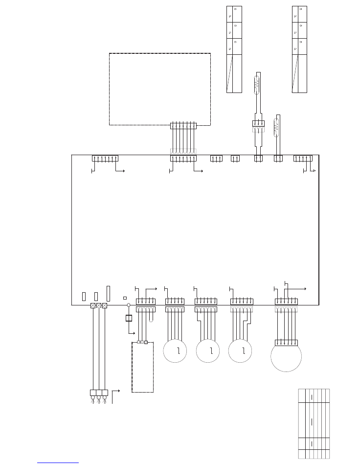
MAIN PCB
ASU18RLF : K09DR-1403HSE-C1
ASU24RLF : K09DR-1404HSE-C1
UL1015
A
WG22
GREEN
EMI FIL
T
ER
ESD-R19
4 TURNS
INDOOR UNIT
CONTROL UNIT
ASU18RLF : EZ-0090DHSE
ASU24RLF : EZ-0104HSE
2015.12.18
6
CN3
Thermistor Characteristics.
Thermistor ( Pipe temp. )
176.0 k
62.9 k
39.6 k
1.1 V
2.2 V
2
.8 V
(20
68 )
°
F
(30
86 )
°
F
(
0
32 )
°
F
Thermistor
T
e
mperature
CN1
Thermistor Characteristics.
Thermistor ( Room temp. )
33.6 k
12.5 k
8.0 k
1.1 V
2.2 V
2
.8 V
(20
68 )
°
F
(30
86 )
°
F
(
0
32 )
°
F
Thermistor
T
e
mperature
DC15V
DC340V
DC12V
DC12V
DC12V
DC12V
DC5V
DC5V
DC5V
CN10 DC Fan motor
6
5
4
3
2
1
Pin No.
T
e
rminal
code
Vm
GND
Vcc
Vsp
PG
Function of terminal
Revolution pulse output
Speed control voltage input
Control power voltage input
GND
Motor power voltage input
Lead wire
color
Red
Black
White
Y
e
llow
Blue
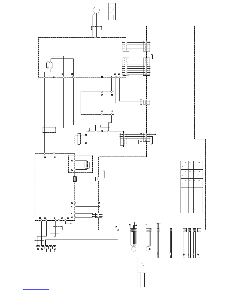
PCB CIRCUIT DIAGRAM
UL3271
A
W
G14 x 3
RED
WHITE
BLACK
COMPRESSOR
EMI FIL
T
ER
ZCA
T
2132-1
130
1 T
9
87
6
5
4
32
1
5
4
32
1
1
2
4
32
1
2
1
2
1
1
23
4
5
6
78
9
1
23
4
5
2
1
UL3271
A
WG20
ORANGE
UL3271
A
WG20
ORANGE
UL1015
A
WG14
BLACK
UL1015
AW
G
1
4
BLACK
UL1015
AW
G
1
4
WHITE
UL1015
AW
G
2
0
BLACK
UL1015
AW
G
2
0
WHITE
UL3271
AW
G
2
0
RED
UL3271
A
WG16
GREEN
UL3271
AW
G
1
4
WHITE
UL3271
A
WG14
WHITE
UL1015
A
WG14
WHITE
UL1015
A
WG14
VIOLET
UL1015
A
WG14
YELLOW
UL1015
A
WG14
BLUE
UL1015
A
WG14
BLACK
UL1015
A
WG14
RED
65
4
32
1
EMI FIL
T
ER
ZCA
T
1518-0730
1 T
EMI FIL
T
ER
ZCA
T
1518-0730
2 T
EMI FIL
T
ER
ZCA
T
1518-0730
1 T
EMI FIL
T
ER
ZCA
T
1518-0730
1 T
EMI FIL
T
ER
ZCA
T
2132-1
130
1 T
EMI FIL
T
ER
ZCA
T
2132-1
130
2 T
EMI FIL
TER
ZCA2132-1
1
30
2 T
UL1015
A
WG14
ORANGE
UL1015
A
WG14
BROWN
1 2 3 4 5 6
1 2 3 4 5
1 2
1 2
1 2 3
1 2 3
1 2 3
1 2 3
UL1007 A
WG24 x 5
WHITE
UL1007 A
WG24 x 9
WHITE
WHITE
WHITE
WHITE
WHITE
WHITE
WHITE
WHITE
WHITE
WHITE
WHITE
WHITE
WHITE
WHITE
UL1015 A
WG20 x 2
UL1007 A
WG24 x 4
BLACK
YELLOW
ORANGE
RED
BROWN
UL1430 A
WG24 x 2
WHITE
BLACK
GRAY
or WHITE
BLACK
UL3271 A
WG14 x 2
UL3271 A
WG20 x 2
BLACK
WHITE
RED
BLUE
ORANGE
YELLOW
WHITE
BLACK
BLACK
RED
RED
BROWN
BROWN
BLUE
BROWN
BROWN
BLUE
BLACK
BLACK
2
3
1
4
+
-
D100
D25XB60
TM101
TM102
W12
B
W13
B
W8
B
W7
B
W17
B
W16
B
TM301
TM302
W306
B
W307
B
TM305
U
TM303
W
TM304
V
CN40
1971032-9
WHITE
I P
M CONTROL
CN42
1971032-5
WHITE
REVERSE CURRENT
CN200
1-1747052-2
RED
VDC I N
CN400
1-1971032-4
RED
ACTPM CONTROL
CN1
1871843-2
WHITE
POWER RELA
Y
CONTROL
CN1
1
0
3-1747052-4
YELLOW
V
A
C I N 1
TM601
TM600
REVERSE CURRENT
CN303
1971032-5
WHITE
I P
M CONTROL
CN301
1971032-9
WHITE
CN800
B5 ( 7-2.3 ) B-XASK-1-A
WHITE
CN700
B05B-PLISK-1
WHITE
CN500
1747052-1
WHITE
CN90
1-1871843-2
RED
CN64
2-1971032-3
BLUE
CN62
1971032-3
WHITE
CN63
3-1971032-3
YELLOW
CN65
1-1971032-3
RED
L1
L2
P
N1
+
-
W4
B
SERIAL
RED
W19
B
W20
B
CT
I N / OUT
W9
B
W21
B
CN100
W25
B
W26
B
W29
B
W28
B
PTC THERMIST
OR
(
AOU24RLXFW1 Only )
ZPR0YCE400A300
W3
B
W18
B
W17
B
W1
B
W2
B
EAR
T
H
1
2
3
L
N
POWER SOURCE
AC208 - 230V
60Hz
T
O
I NDOOR UNIT
M
DC F
A
N MOT
O
R
EXP
ANSION V
A
L
VE COIL
4-W
A
Y
V
A
L
VE COIL
PRESSURE SWITCH
THERMIST
OR ( COMPRESSOR
TEMP
. )
THERMIST
OR ( OUTDOOR
TEMP
. )
THERMIST
OR ( DISCHARGE
TEMP
. )
THERMIST
OR ( PIPE
TEMP
. )
C. M.
CHOKE COIL
L=0.32MH 30A
CAP
A
CIT
O
R PCB
K05FB-0903HUE-P0
(
AOU24RLXFW1 Only )
TRANSIST
OR PCB
( IP
M )
AOU18RLXFW1 : K07BT
-0905HUE-TR0
AOU24RLXFW1 : K07BT
-0906HUE-TR0
I C404
( ACTPM
)
PM601BSG
FIL
T
ER PCB
AOU18RLXFW1 : K09DH-1001HUE-FL0
AOU24RLXFW1 : K09DH-1002HUE-FL0
MAIN PCB
AOU18RLXFW1 : K07BS-1501HUE-C1
AOU24RLXFW1 : K07BS-1502HUE-C1
RED
BLACK
WHITE
YELLOW
BROWN
F.
M
.
7
INVER
T
ER ASSEMBL
Y
AOU18RLXFW1 : EZ-0150EHUE
AOU24RLXFW1 : EZ-0150FHUE
2015.12.25
7
OUTDOOR UNIT
TERMINAL
HP-T3061-3-5P
AC208 - 230V ( ON )
U-V
V-
W
U-W
Compressor
Winding Resistance
0.642
(20
68 )
°
F
1(Red) - 2(Blue)
1(Red) - 3(Orange)
1(Red) - 4(Y
e
llow)
1(Red) - 5(White)
CN700 Expansion V
alve Coil
46.0
Recommended Drive Condition
Unipolar Drive, 1-2 Phase Excitation.
Coil resistance
(20
68 )
°
F
DC15V
DC18V
DC12V
DC340V
DC15V
DC12V
DC15V
Thermistor Characteristics.
Thermistor
Thermistor ( Compressor
. temp. )
CN64
CN65
Thermistor ( Pipe temp. )
Thermistor ( Discharge temp. )
CN63
Thermistor ( Outdoor temp. )
CN62
16.1 k
6.0 k
3.8 k
1.9 V
3.1 V
3
.6 V
168.6 k
62.6 k
40.0 k
0.4 V
0.9 V
1
.2 V
35.2 k
12.6 k
8.0 k
2.6 V
3.8 V
4
.1 V
175.7 k
64.5 k
41.1 k
0.3 V
0.8 V
1
.2 V
(20
68 )
°
F
(30
86 )
°
F
( 0
32 )
°
F
2016.01.07
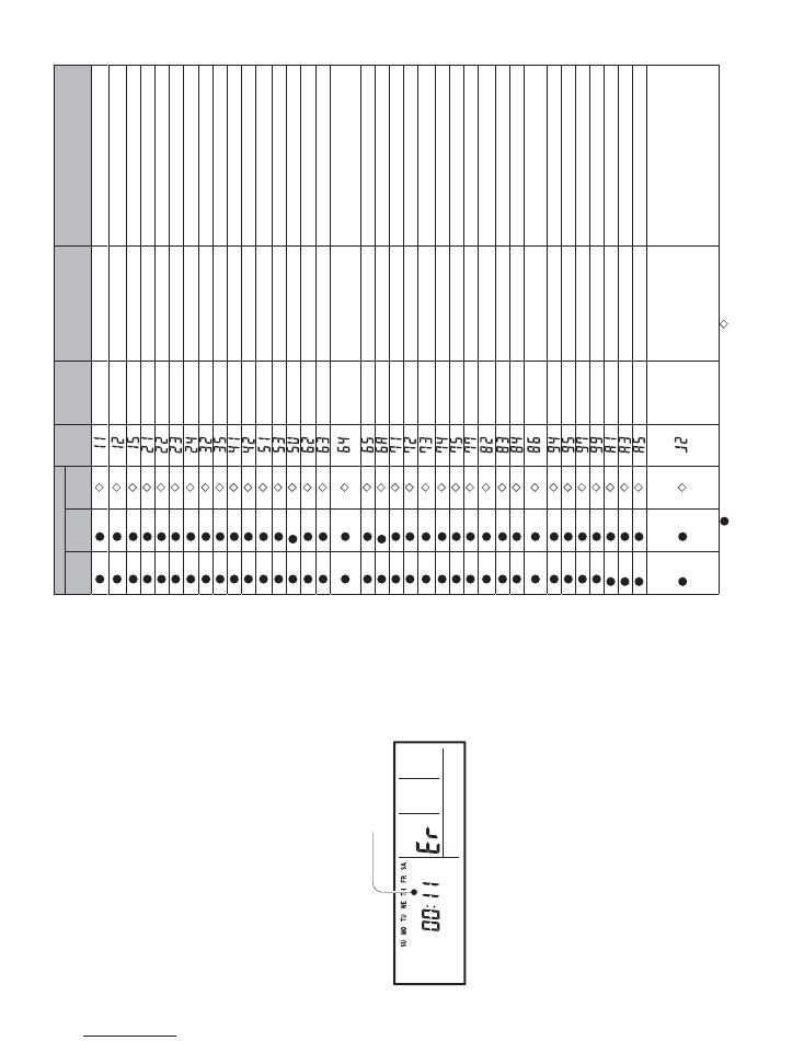
ERROR DETECTION
8
If you use a wired type remote control,
error codes will appear on the remote control display.
If you use a wireless remote control,
the lamp on the photodetector unit will output error
codes by way of blinking patterns.
See the lamp blinking patterns and error codes in the table below.
An error display is displayed only during operation.
Error display
W
ired
remote control Error code
kr
a
m
e
R
N
OI
T
PI
R
C
S
E
D
e
d
o
M
OPERA
TION
lamp
(green)
TIMER lamp (orange)
ECONOMY
lamp (green)
(1)
(1)
Communication
Serial communication error
When the indoor unit cannot receive the signal from the branch unit
When the branch unit cannot receive the signal from the indoor unit
(1)
(2)
Communication
Remote control
communication error
:LUHGUHPRWHFRQWUROFRPPXQLFDWLRQHUURU
(1)
(5)
Communication
Scan error
Check operation incompletion error (normally
, operation disabled)
(2)
(1)
Function setting
Initial setting error
:LULQJPLVWDNH
(2)
(2)
Function setting
Indoor unit capacity error
,QGRRUXQLWFDSDFLW\HUURU
(2)
(3)
Function setting
Connection disabled (series error)
&RPELQDWLRQHUURU
(2)
(4)
Function setting
Connection unit number error
&RQQHFWLRQXQLWQXPEHUHUURULQGRRUXQLW &RQQHFWLRQXQLWQXPEHUHUURUEUDQFKXQLW
(3)
(2)
Indoor unit
Indoor unit main PCB error
,QGRRUXQLW3&%0RGHOLQIRUPDWLRQHUURU
(3)
(5)
Indoor unit
0DQXDODXWRVZLWFKHUURU
0DQXDODXWRVZLWFKHUURU
(4)
(1)
Indoor unit
Room error
,QOHWWKHUPLVWRUHUURU
(4)
(2)
Indoor unit
Indoor unit Heat Ex. sensor error
,QGRRUXQLW+HDW([0LGGOHWKHUPLVWRUHUURU
(5)
(1)
Indoor unit
Indoor unit fan motor error
0DLQIDQPRWRUORFNHUURU 0DLQIDQPRWRUUHYROXWLRQVSHHGHUURU
(5)
(3)
Indoor unit
Water Drain error
'UDLQSXPSHUURU
(5)
(15)
Indoor unit
Indoor unit error
,QGRRUXQLWHUURU
(6)
(2)
Outdoor unit
Outdoor unit main PCB error
2XWGRRUXQLW3&%0RGHOLQIRUPDWLRQHUURU 2XWGRRUXQLW3&%PLFURFRPSXWHUFRPPXQLFDWLRQHUURU
(6)
(3)
Outdoor unit
Inverter PCB error
,QYHUWHUHUURU
(6)
(4)
Outdoor unit
Active filter error, PFC circuit error
V
oltage error stoppage permanently
V
oltage error (can restore)
2YHUFXUUHQWSURWHFWHGRSHUDWLRQVWRSSDJHSHUPDQHQWO\ 3)&KDUGZDUHHUURU
(6)
(5)
Outdoor unit
,30HUURU
T
rip terminal L
error
(6)
(10)
Outdoor unit
Display panel error
0LFURFRPSXWHUVFRPPXQLFDWLRQHUURU
(7)
(1)
Outdoor unit
Discharge thermistor error
'LVFKDUJHWKHUPLVWRUHUURU
(7)
(2)
Outdoor unit
Compressor thermistor error
&RPSUHVVRUWKHUPLVWRUHUURU
(7)
(3)
Outdoor unit
Outdoor unit Heat Ex.
Sensor error
2XWGRRUXQLW+HDW([OLTXLGWKHUPLVWRUHUURU
(7)
(4)
Outdoor unit
Outdoor thermistor error
2XWGRRUWKHUPLVWRUHUURU
(7)
(5)
Outdoor unit
Suction Gas thermistor error
6XFWLRQ*DVWKHUPLVWRUHUURU
(7)
(7)
Outdoor unit
Heat sink thermistor error
+HDWVLQNWKHUPLVWRUHUURU
(8)
(2)
Outdoor unit
Sub-cool Heat Ex. gas
thermistor error
6XEFRRO+HDW([JDVLQOHWWKHUPLVWRUHUURU 6XEFRRO+HDW([JDVRXWOHWWKHUPLVWRUHUURU
(8)
(3)
Outdoor unit
/LTXLGSLSHWKHUPLVWRUHUURU
/LTXLGSLSHWKHUPLVWRUHUURU
(8)
(4)
Outdoor unit
Current sensor error
&XUUHQWVHQVRUHUURUVWRSSDJHSHUPDQHQWO\
(8)
(6)
Outdoor unit
Pressure sensor error
'LVFKDUJHSUHVVXUHVHQVRUHUURU 6XFWLRQSUHVVXUHVHQVRUHUURU +LJKSUHVVXUHVZLWFKHUURU
(9)
(4)
Outdoor unit
Trip detection
T
rip detection
(9)
(5)
Outdoor unit
compressor motor control error
5RWRUSRVLWLRQGHWHFWLRQHUURUVWRSSDJHSHUPDQHQWO\
(9)
(7)
Outdoor unit
Outdoor unit fan motor 1 error
'XW\HUURU
(9)
(9)
Outdoor unit
4-way valve error
ZD\YDOYHHUURU
(10)
(1)
Refrigerant system
Discharge temperature 1 error
'LVFKDUJHWHPSHUDWXUHHUURU
(10)
(3)
Refrigerant system
Compressor temperature error
&RPSUHVVRUWHPSHUDWXUHHUURU
(10)
(5)
Refrigerant system
Pressure error 2
/RZSUHVVXUHHUURU
(13)
(2)
Branch box
Unit flow divider error
((3520DFFHVVHUURU (TXLSPHQWW\SHLQIRUPDWLRQHUURU 6HULDOFRPPXQLFDWLRQHUURUWRRXWGRRUXQLW %UDQFKXQLWVVHULDOFRPPXQLFDWLRQHUURU 6HULDOFRPPXQLFDWLRQHUURUWRLQGRRUXQLW /LTXLGSLSHWKHUPLVWRUHUURU *DVSLSHWKHUPLVWRUHUURU ([SDQVLRQYDOYHIXOOFORVXUHRSHUDWLRQHUURU 5HPRWHFRQWUROOHUFRPPXQLFDWLRQHUURU %UDQFKXQLWHUURU
Display mode
: 0.5s ON / 0.5s OFF
, ( )
: Number of flashing
: 0.1s ON / 0.1s OFF
Wired remote control display (Option)
Error code
9
2016.01.07
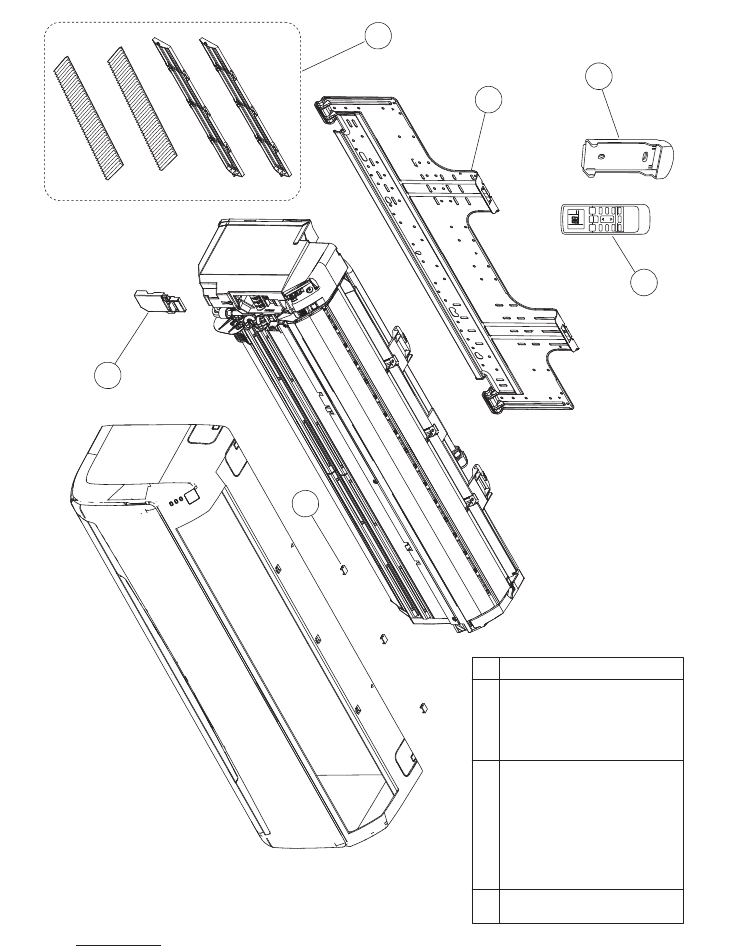
INDOOR UNIT
ASU18RLF
ASU24RLF
PARTS
3
Bracket Panel
Wire Clamper
6
Parts number
Description
Ref
9315023018
9315015013
Screw Cap
5
Air Clean Filter Assy
9309002074
9315212016
1
Remote Control
9379219013
2
4
Remote Control Holder
9305642045
3
6
5
1
2
4
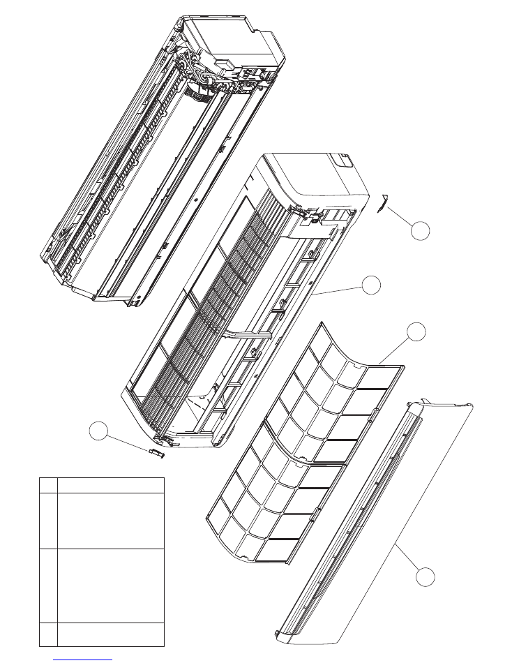
INDOOR UNIT
ASU18RLF
ASU24RLF
10
2016.01.07
11
Front Panel
Air Filter
13
Intake Grille Assy
Parts number
Description
Ref
9314991080
9315014023
12
Grille Clamper
15
14
Receiver Window
9315336163
9306755010
9315010018
14
11
13
15
12
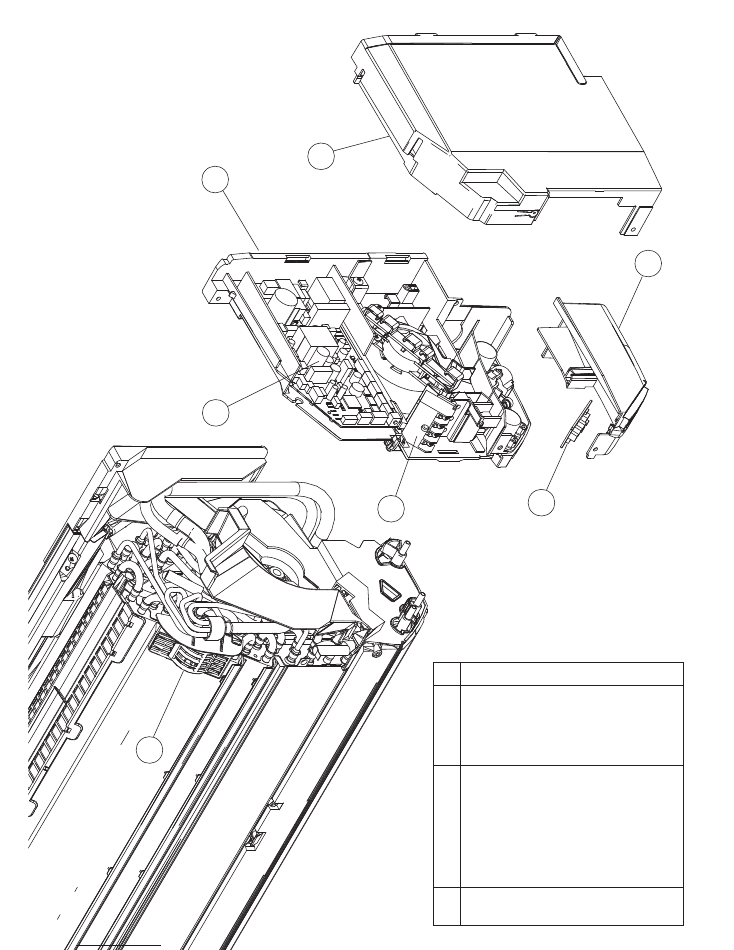
23
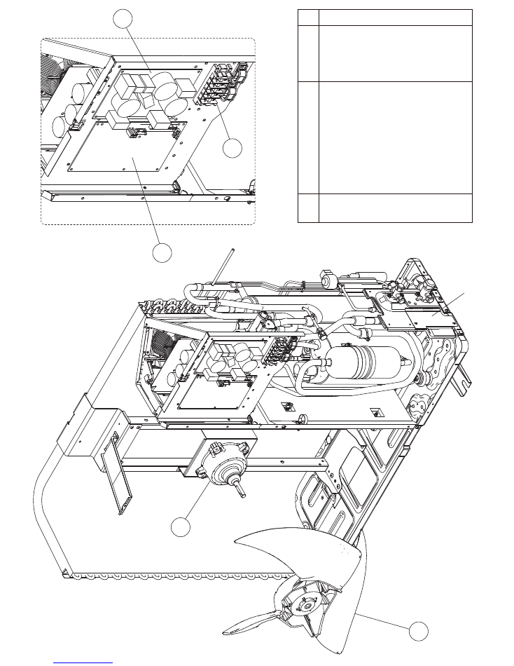
Main PCB (ASU18RLF)
Control Cover
9708540368
23
Main PCB (ASU24RLF)
9708540375
9314997020
21
Control Box
22
9314996023
Terminal
9900447014
24
Indicator PCB
9707210057
26
Display Case
9314999024
25
Room Thermistor Holder
9315252012
27
11
2016.01.06
INDOOR UNIT
ASU18RLF
ASU24RLF
Parts number
Description
Ref
22
24
21
23
25
27
26
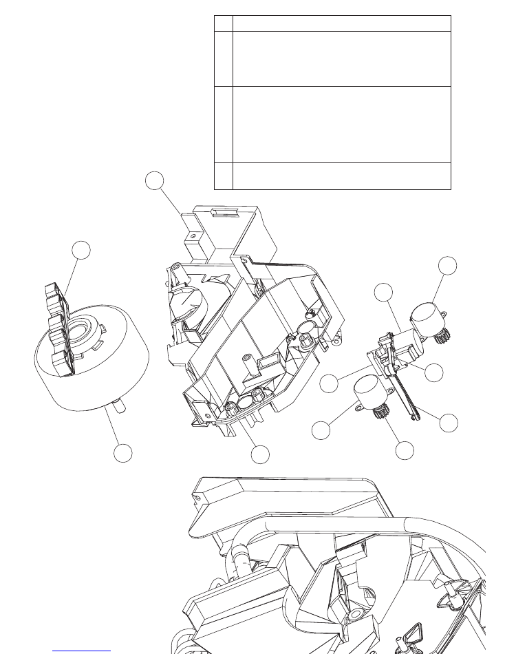
Fan Motor
Motor Clamper
40
9315012012
Bush B
32
9312156016
Motor Step (Red)
41
33
34
35
Motor Step (Green)
Motor Step (Blue)
9602784004
Motor Case
31
9314998027
9900384029
9900384036
9900139063
Link Holder
37
38
39
Link A
Joint A
9315007018
9315008015
9315005014
Gear A
9309994003
36
12
2016.01.07
INDOOR UNIT
ASU18RLF
ASU24RLF
Parts number
Description
Ref
40
41
31
32
35
33
34
36
39
37
38
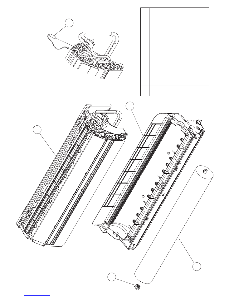
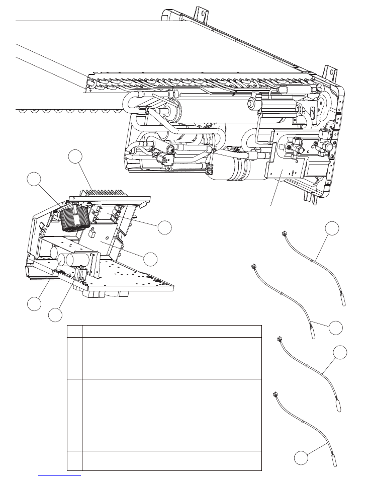
Evaporator Total Assy (24)
53
55
Casing Assy
9315331045
13
2016.01.06
INDOOR UNIT
ASU18RLF
ASU24RLF
Parts number
Description
Ref
51
Crossflow Fan Assy
52
Bearing C Assy
9315024015
9306628017
52
51
55
53
54
54
Pipe Thermistor
9900551018
9315338174
Evaporator Total Assy (18)
53
9315338181
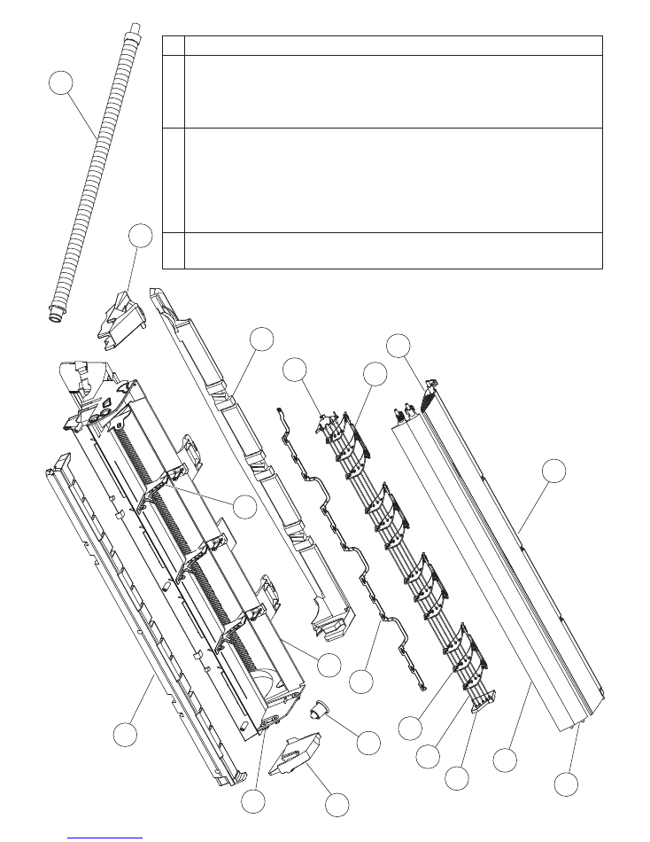
66
63
64
67
62
73
74
65
72
76
75
61
70
78
68
69
71
Parts number
Description
Ref
61
Casing Cover B
63
Casing Cover L
64
Casing Cover R
62
Casing Cover F
65
Drain Cap
9315016010
9315017017
9315018014
9315019011
9367677009
Bush B
72
Spacer D
76
R and L Louver
75
9312156016
9315282019
9311997016
66
Drain Hose Assy
9315769015
67
Casing
9314993015
Louver U (Upper)
68
Louver Z (Lower)
69
Diffuser U
9315000026
9315001023
9315002020
70
Diffuser Z
9
315003027
Piller A
9
315009012
Joint B
9
315006011
71
74
73
Fan Guard
9
305751051
79
Fan Guard Holder Right
9315814012
77
Fan Guard Holder Left
9315815019
78
79
77
14
2016.01.07
INDOOR UNIT
ASU18RLF
ASU24RLF
Casing assy
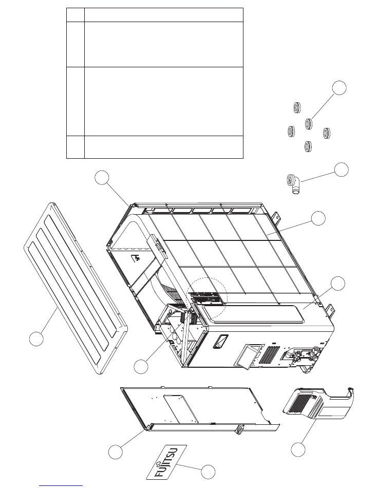
OUTDOOR UNIT
AOU18RLXFW1
AOU24RLXFW1
P
ARTS
2016.01.12
15
7
2
1
8
9
6
5
4
3
3
T
op Panel Sub Assy
9374417032
4
F
ront Panel Sub Assy
9374414079
1
Protective Net
9375381011
9
D
rain Assy
9303029015
10
Drain Cap
313166024302
5
S
ervice Panel Sub Assy
9374415052
7
Right Panel Sub Assy
9374416134
6
Emblem Rear
9351355005
8
V
alve Cover
9374174010
2
T
hermo Holder
9375211011
Ref.
Part number
Description
10
OUTDOOR UNIT
AOU18RLXFW1
AOU24RLXFW1
2016.01.12
16
12
11
13
14
15
14
Filter PCB (AOU24RLXFW1)
9708513072
11
Propeller Fan Assy
9366378020
13
Terminal
Cover plate
9900203023
12
Fan Motor
9602843015
14
Filter PCB (AOU18RLXFW1)
9708513065
15
Main PCB (AOU24RLXFW1)
9708511757
15
Main PCB (AOU18RLXFW1)
9708511740
Ref.
P
art number
Description
OUTDOOR UNIT
AOU18RLXFW1
AOU24RLXFW1
2016.01.12
17
27
30
26
25
29
28
29
ACTPM
9707592016
30
Heatsink
9378530010
25
PTC Thermistor (AOU24)
9704265012
26
Capacitor PCB (AOU18)
9709894033
26
Capacitor PCB (AOU24)
9709894040
28
Transistor PCB (AOU24)
9708512181
28
Transistor PCB (AOU18)
9708512174
27
Choke Coil
9900223014
Valve plate
21
Discharge Thermistor
9900461003
22
Outdoor Thermistor
9900463007
23
Compressor Thermistor
9900466015
24
Heat Exchanger Thermistor
9900514013
Ref.
P
art number
Description
22
23
24
21
Connector
: Blue
Connector : Orange
Connector : Green
Connector
: Red
OUTDOOR UNIT
AOU18RLXFW1
AOU24RLXFW1
2016.01.12
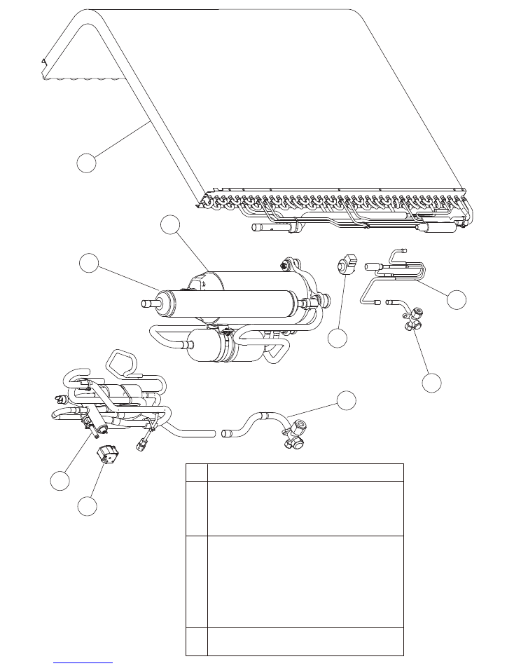
18
35
33
34
39
31
36
32
37
38
Ref.
34
3-way Valve Assy
9377958013
39
3-way Valve Sub Assy
9374470044
36
Compressor
9810135001
35
Accumulator Sub Assy
9374426133
38
4-way Valve Assy
9374425198
37
Solenoid
9970055034
31
Condenser A Sub Assy
9374420308
33
Expansion Valve Assy
9370947144
32
Expansion Valve Coil
9970095030
Part number
Description
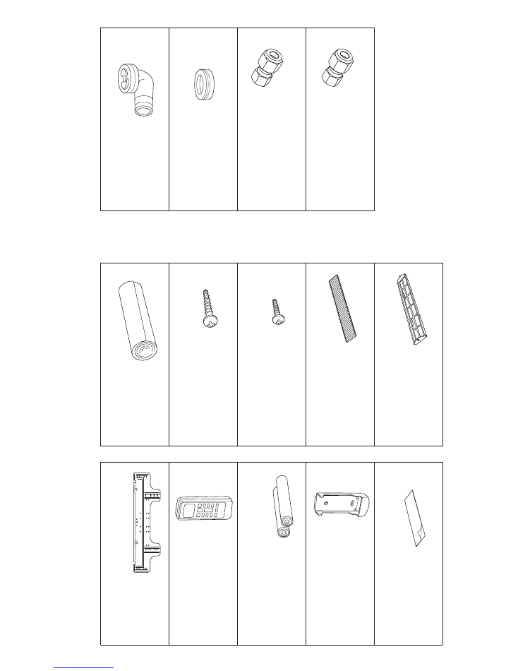
ACCESSORIES
Remote control holder
9305642045
1 piece
Electric filter
9312153060
Ion deodorant filter
9311925071
Remote control
9379219013
1 piece
Battery (penlight)
0600185541
2 pieces shrink pack
Cloth tape
9310519004
1 piece
Tapping screw (big)
M4x 25mm
0700076046
8 pieces
Wall hook bracket
9315023018
1 piece
Tapping screw (small)
0700019036
2 pieces
Air cleaning filter
Adapter G assy
1/2 in. (12.70 mm)
-> 5/8 in. (15.88 mm)
9374749034
1 piece
Adapter E assy
1/4 in. (6.35 mm)
-> 3/8 in. (9.52 mm)
9374749010
1 piece
Air cleaning filter frame
9368568009
2 pieces
OUTDOOR UNIT
INDOOR UNIT
Drain assy
9303029015
1 piece
Drain cap
313166024302
5 pieces
2016.02.10
19
Drain hose insulation
9361756007
1 piece
(AOU18RLXFW1 only)
Adapter is necessary in the
connection of the indoor unit.
For more information, refer
to the installation manual
included with the indoor unit.

1512G4480