Full Text Searchable PDF User Manual
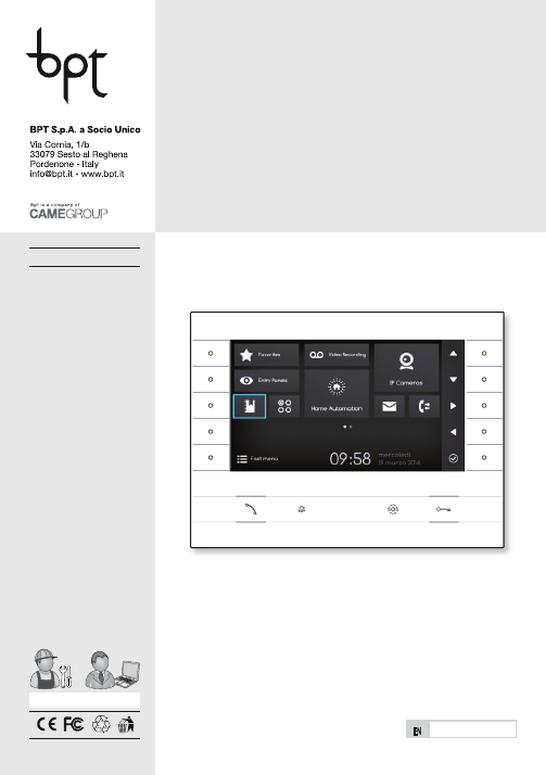
Futura IP
24809760
®
www.bpt.it
English
EN
Futura IP Inst EN 24809760 09-06-14
2
General Notes
• Read the instructions carefully before beginning the installation and carry
out the actions as specified by the maker;
• The installation, programming, commissioning and maintenance of the
product must be carried out only by qualified technical personnel, correctly
trained with regard to respecting the regulations in force, including the
implementation of accident prevention measures and the disposal of
packaging;
• Before carrying out any cleaning or maintenance operation, disconnect
the device from the power supply;
• The equipment must be destined solely for the use for which it was
expressly designed;
• The manufacturer declines all liability for any damage as a result of
improper, incorrect or unreasonable use.
This device complies with the Part 15 of the FCC Rules.
Operation is subject to the following two conditions:
(1) this device may not cause harmful interference and
(2) this device must accept any interference received, including interference
that may cause undesired operation.
Installation
Wall mounting
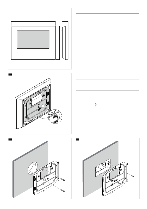
Unfasten the equipment from the metal support by letting it run smoothly
along it after you have pressed the plastic button
A
.
Fix the metal support to the round Ø 60 mm back-box
B
or the rectangular
503 back-box
CD
using the screws provided and paying attention to the
UP direction indication . The box must be installed at an appropriate height
for the user. Avoid tightening the screws too much.
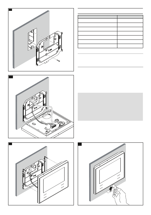
Once the connections are made, hook the video terminal onto the metal
support
EF
. To unfasten the equipment from the metal support press
the plastic button and lift the terminal
G
.
For recessed installation refer to the recessing kit manual.
212
161
29
60
83,5
83,5
2
1
A
C
B
Futura IP Inst EN 24809760 09-06-14
3
Technical features
Type
Futura IP
Local power supply (V DC)
14÷20
Max consumption (mA)
500
Power over Ethernet (PoE)
IEEE 802.3af-PD
Storage temperature °C
-25°C ÷ +70
Operating temperature °C
0 °C ÷ +35
Protection rating (IP)
20
7" LCD TFT colour display (pixels)
800x480
Characteristics of network interface
Ethernet IEEE 802.3 10/100 Base T(X), auto speed, auto half/full duplex
mode, auto MDI/MDI-X
Functional characteristics
Standard SIP protocol (rfc3261), audio and video
Codec video H.264
Codec audio G711A, G711µ
LAN/PoE
H①
Socket for connecting device to LAN or LAN PoE network.
Note: The device automatically recognises the local or PoE power supply.
DISPOSAL
Make sure the packaging material is not disposed of in nature, but rather
disposed of in compliance with the laws in effect in the country in which
the product is being used.
At the end of the product’s life cycle, make sure it not disposed of in nature.
The equipment must be disposed of in compliance with current laws and
its components recycled where possible. The components that should be
recycled are marked with the material’s ID marker.
E
D
1
G
F
Futura IP Inst EN 24809760 09-06-14
4
M1
LAN/PoE
②
①
Terminal board
H②
+
Local power supply
–
+
Doorbell
–
AL
Alarm Input
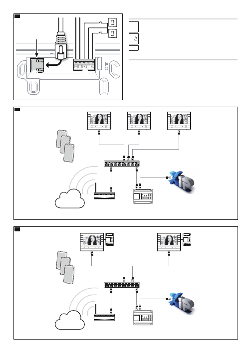
Installation diagrams
Diagram for installation with devices powered by PoE Switch
I
Diagram for installation with locally powered devices
J
• With VAS/101 power supply: 2 Futura IP devices, total max 100mt with
0.5mm
2
section cable.
• With VAS/100.30 power supply: up to 3 Futura IP devices, total max 100mt
with 0.5mm
2
section cable.
Switch PoE
ETI miniser
Router ADSL
(default GW)
VAS/101
VAS/101
M2
M1
+
–
M2
M1
+
–
Switch
ETI miniser
Router ADSL
(default GW)
Internet
Internet
Switch PoE
ETI miniser
Router ADSL
(default GW)
VAS/101
VAS/101
M2
M1
+
–
M2
M1
+
–
Switch
ETI miniser
Router ADSL
(default GW)
Internet
Internet
I
J
H
Futura IP Inst EN 24809760 09-06-14
5
Configuration and commissioning through the device interface
Preliminary operations on PCS Xip
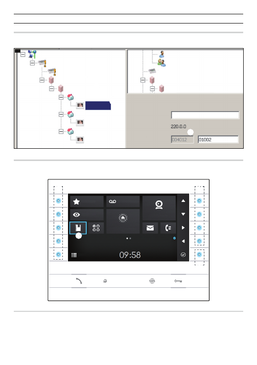
The device is a constituent part of a system based on the Xip system. For this reason the system structure must have been previously constructed using the
PCS Xip software.
K
①
②
③
④
⑤
IP RECV 7
IP RECV 7
IP RECV 7
IP 3 unit
IP 2 unit
IP RECV 7 properties
Name
Address
SIP User Name
IP RECV 7
IP 1 unit
Sub block IP
IP 1 block
ETI
ETI/miniSER
XIP Multi server
Concierge
Group of concierges
ETI
Block IP
Sub block IP
Detecting the "SIP User Name" of the device
K
Create the IP block
①
and Sub block
②
; add the IP units
③
and lastly the IP receivers
④
; select the desired IP receiver. In the properties window you can
see
⑤
the code to use as "
SIP User Name
" to configure the receiver.
Favourites
Video Recording
Entry Panels
Fast Menu
Wednesday
19th March 2014
Home Automation
IP Cameras
⑨
⑦
⑧
⑥
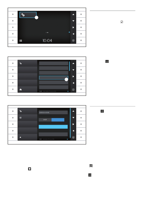
Browsing in the interface
Note: The appearance of the home page may vary according to how the system or User interface is configured.
The area highlighted in blue on the display
⑥
indicates the element selected; use the buttons on the right of the receiver
⑦
to move the selection in the
direction indicated by the arrows on the screen; once the desired element is highlighted, press button
⑧
to open the section connected to it.
The function of buttons
⑨
located on the left of the screen varies depending on what is shown on the screen.
Note: active buttons are highlighted by the blue LED coming on.
Futura IP Inst EN 24809760 09-06-14
6
⑩
⑪
Settings
Settings
System Info
Languages
Date and Time
Network
SIP
Codecs
Fast Menu
Home
Wednesday
19th March 2014
Network
MAC ADDRESS
MODE
192.168.1.4
255.255.255.0
Static
IP ADDRESS
NETMASK
Back
Save
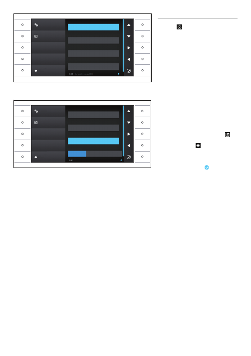
Receiver settings
Use the buttons on the side of the receiver to move the
selection until you get to page 2 of the home page.
Select the button to access the device's setting options
⑩
and press the button next to the icon.
Select the section called “
Network
”
⑪
and press the
button next to the icon.
Note: some sections of the menu require the installer
password to be entered before they can be changed.
The default password is "112233".
The "Network" menu
Note: to fill in the selected field, press the button
next to icon and use the keyboard that appears.
MAC ADDRESS
: The Mac address of the device cannot
be changed.
MODE
: Lets you choose the type of address from:
DHCP: The IP address of the device is assigned by the
DHCP server.
Static: The IP address of the device is manually
assigned.
IP ADDRESS
: If you have chosen to use a static IP, enter
the device's IP address in this space.
The address must belong to the same subnet as the router and the other devices connected; the default address is "192.168.1.4".
NETMASK
: Indicate the subnet mask (if different from the default setting).
GATEWAY
: Should it be necessary to route data traffic towards other subnets, you can indicate a gateway in the relevant space.
Once all the necessary data have been entered, save the setting by pressing the button next to the icon.
Press the button next to icon to access the list of options that can be set.
From the list select the section of the menu dedicated to the SIP and press the button next to the icon.
Futura IP Inst EN 24809760 09-06-14
7
Sip
USERNAME
PASSWORD
00401201002
192.168.1.3
DISPLAY NAME
SERVER
Back
The SIP menu
Note: to fill in the selected field, press the button
next to icon and use the keyboard that appears.
USERNAME
: In this space enter the “
SIP User Name
”
assigned to the device by PCS Xip.
PASSWORD
(absent by default): In this space enter the
password assigned in the Xip receiver credentials in the
server setup window.
DISPLAY NAME
(option available only for systems
without XIP Servers): In this space enter the name that
you want to give to the device.
SERVER
: In this space enter the server's IP address.
Default IP addresses of Bpt servers:
ETI/MiniSER Xip - 192.168.0.3 (port 0) - 192.168.1.3
(port 1)
ETI/SER Xip, 192.168.1.1
SERVER TYPE
: Choose the type of server the device is
connected to from:
XIP Server: Bpt server
Generic: non-Bpt server
None: if no server is present
Once all the necessary data have been entered, save
the setting by pressing the button next to the icon.
Press the button next to icon to access the list of
options that can be set.
If all the operations have been carried out correctly
and if the SIP server is on, the icon will be visible
on the home page and on all the pages it features on,
which indicates that the device has been registered
with the server.
The lists of the entry panels and receivers present on the
network, which the device can communicate with, will
be populated automatically by the server.
Save
Sip account
Save
PASSWORD
192.168.1.1
XIP Server
Generic
None
DISPLAY NAME
SERVER
SERVER TYPE
Back
Futura IP Inst EN 24809760 09-06-14
8
L
M
®
VAS/101
M2
M1
+
–
Switch PoE
®
192.168.1.4
192.168.1.100
192.168.1.4
192.168.1.100
®
VAS/101
M2
M1
+
–
Switch PoE
®
192.168.1.4
192.168.1.100
192.168.1.4
192.168.1.100
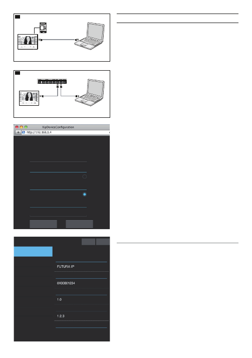
Configuration and commissioning via the WEB interface
Configuring the device can also be carried out via the WEB interface; to do this it is
necessary to assign to your PC an address belonging to the same subnet as the device.
If the device is powered locally, it is possible to connect it directly to your PC, via a
LAN cable
L
.
If the device is powered by PoE switch, the connection diagram is as shown in
figure
M
.
Access the settings web page by entering the address of the device that you wish to
configure in the address bar of your browser (Chrome, Firefox, Safari).
Select the “
INSTALLER
” access option and enter the password, by default “
112233
”,
to access the settings windows.
Note: Access with the "User" credentials (default password 123456) only lets
you consult the following pages, with the exception of operations relating to
updating firmware which can also be carried out by the User.
Note: There is no scroll bar on the right on the settings web pages. To scroll
through the web pages, press and hold down the right-hand mouse button and
drag. On a smartphone or tablet drag your finger across the screen:
System information
This window gives technical information that is useful for identifying the device's
characteristics, the hardware and software version, and the SIP account status.
Futura IP Inst EN 24809760 09-06-14
••••••
Futura IP
SETTINGS
LOG-IN MODE
USER
INSTALLER
PASSWORD
Language
Enter
System Info
System Info
Help
Exit
MODEL
SN
HW VERSION
SW VERSION
ACCOUNT STATUS
Not available
Date and Time
Network
SIP
Maintenance
Diagnostics
Voicemail
9
Futura IP Inst EN 24809760 09-06-14
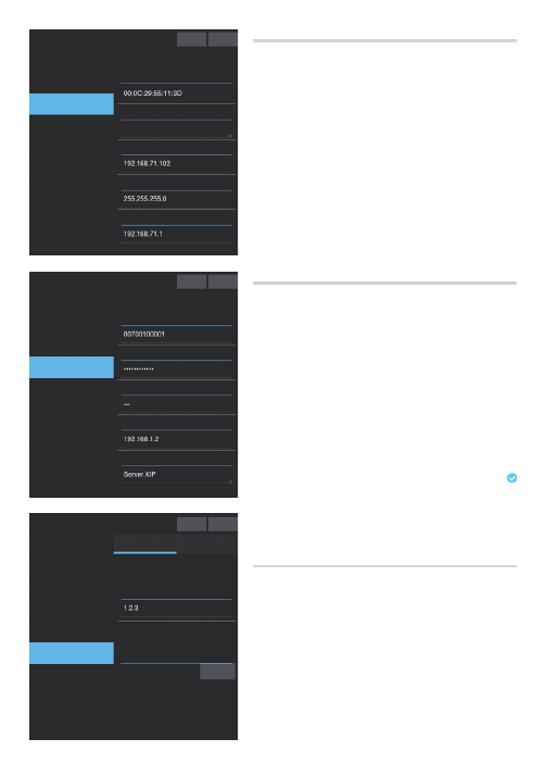
Network
MAC ADDRESS
: The Mac address of the device cannot be changed.
MODE
: Lets you choose the type of address from:
DHCP: The IP address of the device is assigned by the DHCP server.
Static: The IP address of the device is manually assigned.
IP ADDRESS
: If you have chosen to use a static IP, enter the device's IP address in
this space. The address must belong to the same subnet as the router and the other
devices connected; the default address is "192.168.1.4".
NETMASK
: Indicate the subnet mask (if different from the default setting).
GATEWAY
: Should it be necessary to route data traffic towards other subnets, you can
indicate a gateway in the relevant space.
To save the changes made or reload the previous data, press the relevant button that
will appear at the bottom of the page.
To save the changes made or reload the previous data, press the relevant button that
will appear at the bottom of the page.
Select the section called SIP from the list.
SIP
USERNAME
: In this space enter the “
SIP User Name
” assigned to the device by PCS Xip.
PASSWORD
(absent by default): In this space enter the password assigned in the Xip
receiver credentials in the server setup window.
DISPLAY NAME
(option available only for systems without XIP Servers): In this space
enter the name that you want to give to the device.
SERVER
: In this space enter the server's IP address.
Default IP addresses of Bpt servers:
ETI/MiniSER Xip - 192.168.0.3 (port 0) - 192.168.1.3 (port 1)
ETI/SER Xip, 192.168.1.1
SERVER TYPE
: Choose the type of server the device is connected to from:
XIP Server: Bpt server
Generic: non-Bpt server
None: if no server is present
To save the changes made or reload the previous data, press the relevant button that
will appear at the bottom of the page.
If all the operations have been carried out correctly and if the SIP server is on, the
icon will be visible on the receiver's home page and on all the pages it features on,
which indicates that the device has been registered with the server.
The lists of the entry panels and receivers present on the network, which the device
can communicate with, will be populated automatically by the server.
Maintenance
Through this window you can update the device's firmware by proceeding as follows:
Press the "Charge" button, select the file containing the firmware update in your
computer, and start up the process.
Network
Help
Exit
MAC ADDRESS
MODE
IP ADDRESS
NETMASK
GATEWAY
Static
System Info
SIP
Help
Exit
USERNAME
PASSWORD
DISPLAY NAME
SERVER
SERVER TYPE
Date and Time
Network
SIP
Maintenance
Diagnostics
Voicemail
System Info
Maintenance
No file selected
Help
Exit
Load
VERSION
UPDATE
CONFIGURATION
FILE
Date and Time
Network
SIP
Maintenance
Diagnostics
Voicemail
System Info
Date and Time
Network
SIP
Maintenance
Diagnostics
Voicemail

10
Futura IP Inst EN 24809760 09-06-14
System Info
Diagnostics
Help
Exit
Reload
Save
Remote
Error
LOG LEVEL
STATISTICS
LOG FILES
MODE
IP ADDRESS
Date and Time
Network
SIP
Maintenance
Diagnostics
Voicemail
Diagnostics
STATISTICS
This section brings together statistical data on the operation of the device.
LOG FILES
This section lets you generate files containing data of use to technical service in
identifying the causes of any possible problems.
LOG LEVEL
: lets you choose the accuracy and type of LOG files to collect.
MODE
: lets you choose where to save the LOG files from:
Local-RAM: the file is saved in the device's temporary memory
Local-FLASH: the file is saved in the device's internal memory
(warning! capacity is limited)
Remote: the file is saved on a remote server
IP ADDRESS
: give the IP address of the remote server in this space.

11
Futura IP Inst EN 24809760 09-06-14
