Full Text Searchable PDF User Manual
HOUSEHOLD INSTANT GAS WATER HEATER
(Flue Exhaust Type)
INSTRUCTION MANUAL
8l, 12l, 16l, 20l
Certified to ISO9001
LPGSASA Permit No 1008-26/1-RSA-12-A
Indoor & Outdoor Use
Please read the manual carefully and understand the operation prior to installation and use.
The registered LPGSASA gas practitioner must commission the gas water heater before you sign the certificate of
compliance.
Retain this manual for future reference.
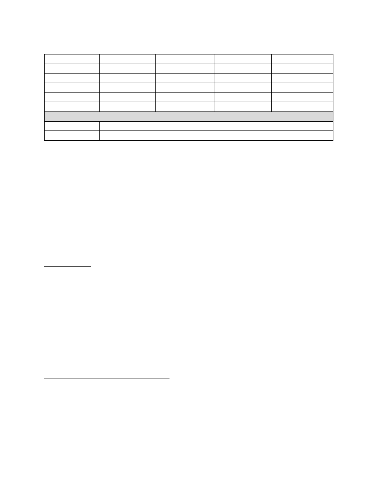
Technical Data
Name
8lt
12lt
16lt
20lt
Model No
JSD 16-LN1
JSD 24-LN1
JSD 32-LN1
JSD 40-LN1
Type of Gas
LPG
LPG
LPG
LPG
Consumption at MAX
1.50 kg/h
2.25 kg/h
3.0 kg/h
3.75 kg/h
Operating Pressure
2.8 kPa
2.8 kPa
2.8 kPa
2.8 kPa
Permit No
1008-26/1-RSA-12-A
1008-26/1-RSA-12-A
1008-26/1-RSA-12-A
1008-26/1-RSA-12-A
Product Type
CLASS 'B' FOR INDOOR INSTALLATION. CAN BE INSTALLED OUTDOORS BUT
MUST
BE FLUED
FLUE AVAILABLE FROM GEYSER INSTALLER
Gas Consumption as per Technical data sheet above
The unit is to be installed by a certified LPGSASA gas practitioner
If the unit is installed outside the gas water heater MUST be flued
This gas water heater will switch off within 4 minutes if no flue is fitted
NB
- Only a SANS 1237 Approved 2.8kPa regulator must be fitted
NB
- This appliance must be installed in accordance with SANS 10087 part 1
NB
- This appliance must
ONLY
be installed by a LPGSASA installer
For Your Safety
This appliance is set to operate on LPG only
If you smell gas;
•
Turn off the gas supply at the cylinder / bottle
•
Extinguish ALL naked flames
•
Do NOT operate any electrical appliances
•
Ventilate the area
NB
- Should the odour persist, contact your local dealer or gas suppliers immediately
Burn - Back (Fire in the tube or chamber)
In the event of a burn-back, immediately turn off the gas supply at the cylinder valve. After
ensuring that the naked flame is extinguished, re-open and re-light the appliance in the normal
manner. Should the appliance burn-back again, close the control valve and phone a service
technician.
Do NOT use the appliance again until the service technician has declared that it is safe to do so.

Gas Pressure Regulator
This appliance requires an operating pressure of 2.8 kPa at the appliance. A suitable LPG
regulator that complies with the requirements of SANS 1237 must be installed / used.
Important Information to the User
This appliance may ONLY be installed by a certified LP gas installer. All registered installers are
issued with a card showing their registration number. Ask to be shown the card before allowing
any installation to commence and make note of the installer QCC number.
Upon completion of the installation, the installer is required to explain the operation details of
the appliance together with the safety instructions. You will be asked to sign acceptance of the
installation and be provided with a completion certificate.
You should only sign for acceptance of the installation when the installation is completed to
your satisfaction. Note that your invoice is required in the event that you wish to make a
guarantee claim.
Important Information to the Installer
This appliance may only be installed by an LP gas installer, registered to the Liquefied Petroleum
Gas Association of Southern Africa. The appliance must be installed in accordance with the
requirements of SANS 10087-1 and any fire department regulation and / or local bylaws
applicable to the area.
If in doubt, check with the relevant authority before undertaking the installation. Upon
completion of the installation, you are required to fully explain and demonstrate to the user the
operational details and safety practices applicable to the appliance and installation.
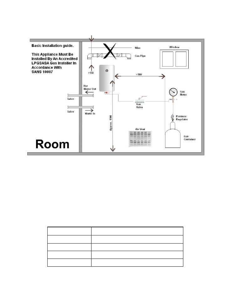
Correct Indoor Installation
If flexible hose is being used, it MUST be BS3212 of SANS1156 approved hose. The hose MUST
NOT be longer than 2 meters. The hose should NOT be fed directly through a wall or
cupboard, neither should it be behind or above the gas water heater.
We DO NOT recommend using hose for the gas connection. This will restrict the gas flow and
volume and will underperform, as a result. We recommend to use copper, composite stainless-
steel flex pipe.
Air Entry and Vent Area Requirements
Thermal Burner (KW) Min area of the Air-In Hole and Vent Hole (Cm²)
<12
100
12 - 16
130
16 - 20
160
20 - 26
200
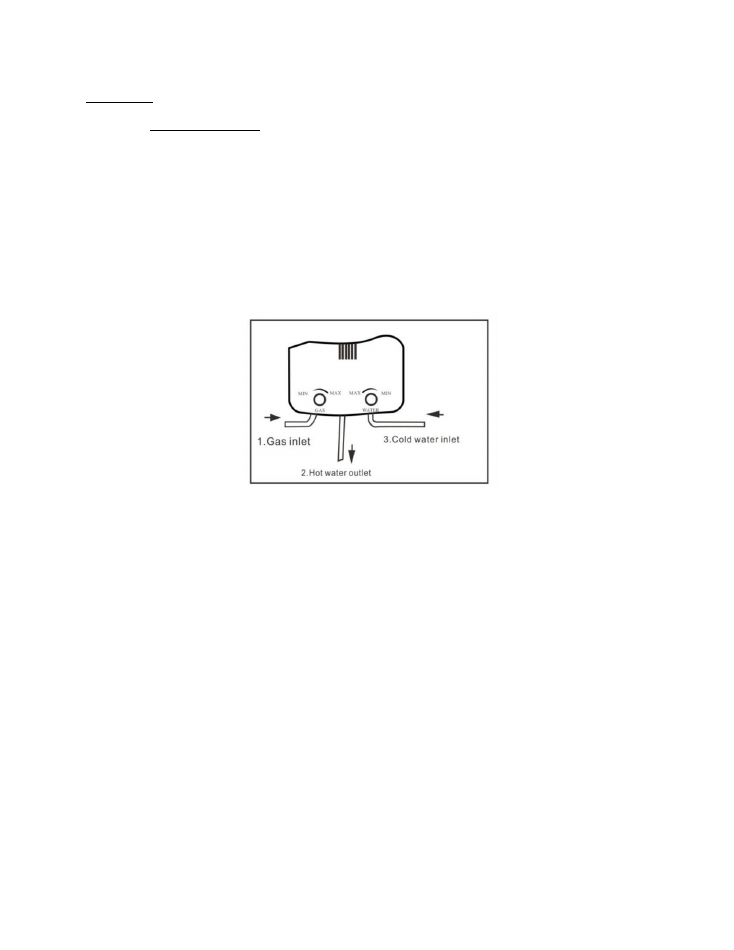
Installation
Gas inlet
–
Use two wrenches
(It will break if held with one wrench at the gas water heater
outlet)
Use a swivel fitting as supplied
NB
- Hot water outlet
–
It is recommended to fit a FULL-BORE water valve. Do NOT use flex type
toilet connectors. The flow will be restricted and will result in gas water heater failure
Cold water inlet
–
Flush the cold-water pipe before connecting to free the pipe of dirt. When
using water from a storage tank, it is recommended to fit an inline water filter.
Do NOT use flex type toilet connectors.
Preparation
The gas water heater ignition function is powered by two large 1.5V. DC (Type D) torch
batteries. Please insert the correct way as indicated on the battery housing.
Batteries are NOT included.
Ignition
Open the gas at the cylinder valve and the gas valve after the regulator.
Open the warm water tap. The electronic ignitors will light up the main burners after 6 to 10
seconds.
First time ignition after installation, or when changing the cylinder, might take longer as there
will be air inside the gas pipe. Repeat if ignition is not obtained within the 10 seconds.
NB
- Remember that the installer must by law commission your newly installed water heater in
your, or your representative’s presence, before you sign off the installation.

Installation of Flue
Setting up the Air Vent
The air vent should be as near to the floor as possible, but below the halfway distance of the
total distance to the ceiling.
The exhaust flue should be to the outside of the room and properly sealed to prevent exhaust
fumes entering to the inside.
The bend to the outside will not be less than 250mm from the centre of the flue to the gas
water heater connection.
Precautions
As a precaution, if you are away from home and the gas water heater will not be used for some
time, CLOSE THE CYLINDER VALVE. Always close the cylinder valve first before changing the
empty cylinder with a full cylinder.

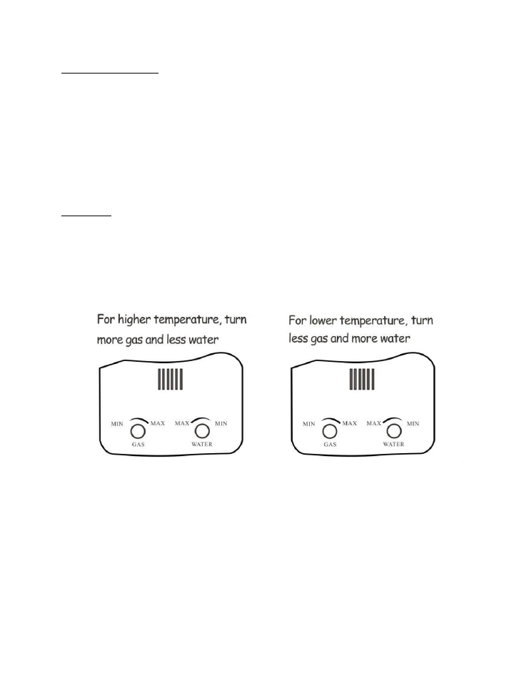
Temperature Control
To adjust;
Use clearly marked controls on the gas water heater control panel. You can adjust the flame
from low to high as well as the required water flow.
Should the water flow be too high, close the valve at the cold-water inlet slightly.
Shut-Off
The gas water heater will shut off automatically when you close the warm water supply. It will
also shut off if you close the cold water supply to the gas water heater, or if you close the
cylinder valve.
This gas water heater MUST NOT be used for anything other than the heating of water.
NB
–
The gas water heater should not be used continuously for periods longer than 20 minutes
at a time.
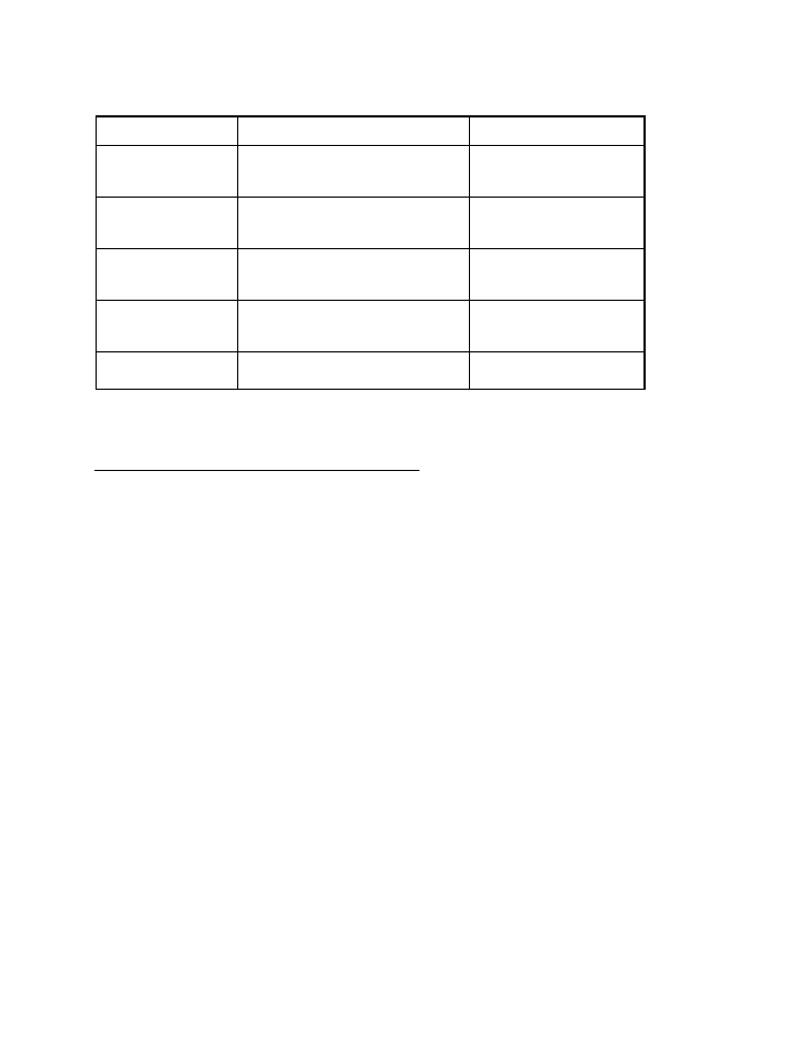
Trouble Shooting
Protective Function
Reaction
Solution / Remarks
Water Pressure Too High
If Water Pressure is Over 0.8Mpa, the Water-Out
Valve will Release Water and Lower the Pressure
Increase Valve Pressure Limit
According to Local Water Supply
Pressure
Water Pressure Too Low
If Water Pressure is Below 0.025Mpa the Water
Heater Cannot be Ignited
Water Pressure Pump to be Fitted or
Use Water Heater when Pressure is
Higher
20 Minute Auto Shut Off
Shuts Off Automatically After 20 Minutes of Use
Restart Water Heater
Low Battery
Although a Spark Sound can be heard the Battery
Power is too Low to Open the Solenoid Valve
Change to New Quality Batteries
Over Heat Protection
Water Heater Automatically Shuts Off when Water
Temperature is Above 77˚C
Restart Water Heater When Water
has Cooled
Repair and Maintenance
–
by Professional Person
Gas water heaters MUST be checked by a professional person annually. The following points
MUST be checked;
Leaks on the gas connections.
Leaks on water in and outlets.
Water inlet sieve
–
free from dirt and clogging
–
clean if necessary.
All parts functioning 100%
Flame quality and combustion (Soot)
Carbon accumulation on heat exchanger
–
clean if necessary.
No combustion leaks to the inside of the room.
Gas regulator
–
checked.
Clean carbon accumulation and oxidation on ceramic ignitors
–
if necessary.

Repair and Maintenance
–
by Owner
Clean the outside cover with warm water and a mild detergent using a soft cloth.
Do
NOT
use any abrasive cleaners or scourers.
Clean the cover vents with a soft brush.
Check the flue, make sure there are no obstructions. After cleaning, make sure that the flue is
properly fitted so that NO combustion will be released to the inside of the room.
Make sure that NO dirt is dropped to the inside of the gas water heater.
Check fittings and connections regularly with a 50/50% soap and water solution for gas leaks.
If there is a leak, stop using the gas water heater and close the valve on the cylinder.
Remove the batteries from the gas water heater.
Contact your installer or your local qualified gas dealer.
Do NOT use the gas water heater for any other purpose except for producing hot water i.e.
drying clothes
–
this will block the air vents
Always drain the water at the water exhaust if the gas water heater is not to be used for some
time, or if
the temperatures drop below 0˚C ambient temperature.
Tampering
Under NO circumstance may an unauthorized person tamper with the unit. ONLY authorized
LPGSASA certified persons may carry out repairs to the unit. For anyone else to do so is not only
extremely dangerous, but AGAINST THE LAW
–
SANS 347
Department of Labour, Pressure Equipment Regulations, South African National Standard
(DOL / PER)
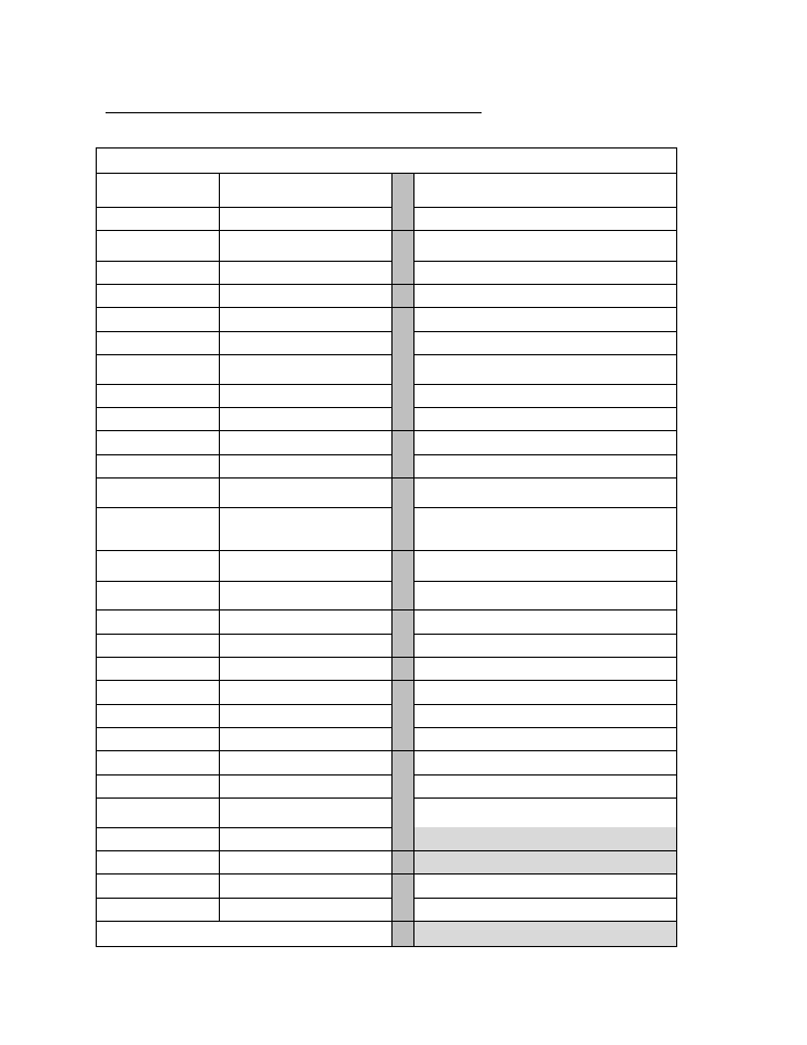
Maintenance and Repair Guide to Common Malfunctions
Cause / Malfunction
Solutions
Improper Operation
Gas Valve not Open
Open Gas Valve
Water Supply not Open
Open Water Valve
Improper Regulation Method of
Water temp
Increase Gas Volume, Reduce Water Volume
Reduce Gas Volume, Increase Water Volume
Improper Position of Water Switch
Turn Water Switch to Hot Water Position
Air in Gas Feed Line
Open and Close Hot Water Supply Several Times
Inadequate Fresh Water Supply
Improve Ventilation and Ensure Air Supply
Gas Pressure
Gas Pressure too High
Regulate Pressure Relief Valve - Reduce Overall Gas
Supply
Gas Pressure too Low
Check for any Twists in Gas Supply Hose
Water Pressure
Water Pressure too High
Reduce Water Supply
Water Pressure too Low
Utilize when Water Pressure is back to Normal
Surroundings &
Gas Valve is Half Opened
Open Gas Valve Completely
Inadequate Supply of
Gas
Gas Feed Hose is too Long
Check for Correct Hose Size and Length
Diameter of Joints too Small
Check for Restrictions in Gas hose. Use Full Bore Valves
&
Fittings
Improper Pressure Relief Valve
Water Heater of a Content Over 8lt - Pressure Relief
Valve (LPG) 1.2m 3kg/h
Simultaneous Consumption of Gas
by Several Users
Stop Other Users from Using the Gas
Blockage of Water Route
Clean Filtration Net on Water Admitting Orifice
Blockage of Shower
Clean Shower Device
Blockage of Vent Pipe
Clean Flue Pipe
Inadequate Battery Voltage
Replace Batteries with Quality Batteries
Low Water Temperature
Reduce Water Volume
Safety Protection
Exorbitant Air Pressure Protective
Device
Utilize when Air Pressure Recovers to Normal
Electrical Leakage Protective Device
Professional Repair Only
Heat Protective Switch
Professional Repair Only
20 Minute Protective Device
Re-open Hot Water Valve
Other Causes
Professional Repair Only

The installer MUST use two wrenches
One to hold the gas inlet on the gas water heater
and one to tighten the ½” swivel to 15mm
copper solder
–
supplied.
This is the correct way to install the gas inlet, without breaking the pipes.
If using a ½” female to
hose tail connection with an 8mm hose, the gas flow volume will be
inhibited and this will decrease the gas pressure.
This gas water heater operates on gas pressure 2.8 kPa ONLY. Do not increase pressure.
If Installed Inside, ensure that;
The installer abides by SANS 10087-1 specifications of cross ventilation.
NB
- If installed outside, a flue must be fitted as this unit is fitted with a flue sensor.
NB
–
If installed inside, a flue must be flued to the outside of the building.
NB
- By Law, it must cut out within 4 minutes if no flue is fitted.
NB
- Bridging out of the flue sensor is not permitted.
NB
–
A valid COC Certificate must accompany any warranty claim.
Rev 0
–
11/2017