Full Text Searchable PDF User Manual
Yingli Solar PV Modules, Installation and User Manual
page 1
This manual applies to photovoltaic modules (“PV modules”,
also commonly known as solar panels) manufactured by
Yingli Green Energy Holding Co. Ltd. (“Yingli Solar”), and
is explicitly written for qualified professionals (“Installer”
or “Installers”), including without limitation licensed
electricians and RAL Certified PV Installers.
I N T R O D U C T I O N
Thank you for choosing Yingli Solar as your PV module provider. We
appreciate your business! This manual contains important information
pertaining to the electrical and mechanical installation and maintenance
of PV modules, and contains safety information that you must read carefully
and be familiar with before handling, installing, and/or maintaining Yingli Solar
PV modules.
Yingli Solar does not assume responsibility and expressly disclaims liability for
losses, damages, or expenses arising out of, or in any way connected with this
Installation and User Manual. Yingli Solar assumes no responsibility for any
infringement of patents or other rights of third parties, which may result from
using Yingli Solar PV modules. No license is granted expressly or by implication
or under any patent or patent rights. The information in this manual is believed
to be reliable, but does not constitute an expressed or implied warranty. Yingli
Solar reserves the right to make changes to its PV modules and other products,
their specifications, or this manual without prior notice.
Yingli Solar and its subsidiaries are not liable for any damages caused by
inappropriate installation, use, or maintenance of Yingli Solar PV modules,
including without limitation damages, losses, and expenses caused by non-
observance of the instructions of this manual or caused by or in connection with
products of other manufacturers.
Yingli Solar PV modules are designed to meet the requirements for the standards
IEC 61215 and IEC 61730, application class A. Modules rated for use in this
application class may be used in systems operating at greater than 50 V DC
or 240 W, where general contact access is anticipated. Modules qualified for
safety through IEC 61730-1 and IEC 61730-2 and within this application class are
considered to meet the requirements for safety class II. In the course of the PV
module certification process, the compliance of this manual with the certification
requirements has been verified by an independent certification laboratory.
This Installation and User Manual is available in different languages. In cases of
discrepancy between versions, the English language version shall control.
Failure to comply with the requirements listed in this manual will invalidate the
Limited Warranty for PV Modules as provided by Yingli Solar at the time of sale
to the direct customer. Additional recommendations are provided to enhance
safety practices and performance results. Please provide a copy of this manual
to the PV system owner for their reference, and inform them of all relevant
aspects of safety, operation, and maintenance.
S A F E T Y
General
You must understand and follow all applicable local, state, and federal
regulations and standards for building construction, electrical design, fire,
and safety, and must check with local authorities to determine applicable
permitting requirements before attempting to install or maintain PV modules.
Rooftop PV systems should only be installed on dwellings that have been
formally analyzed for structural integrity, and confirmed to be capable
of handling the additional weighted load of PV system components,
including PV modules, by a certified building specialist or engineer.
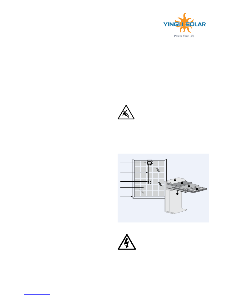
For your safety, do not attempt to work on a rooftop until
safety precautions have been identified and taken, including
without limitation fall protection measures, ladders or
stairways, and personal protective equipment (PPE).
For your safety, do not install or handle PV modules under adverse conditions,
including without limitation strong or gusty winds, and wet or frosted roof surfaces.
The flat-plate PV module construction consists of a laminated assembly
of solar cells encapsulated within an insulating material with a rigid
glass surface and an insulated substrate. The laminated assembly is
supported by an aluminum frame that is also used for mounting the
module. See Figure 1 for an illustration of the PV module components.
Figure 1: Module components and cross-section of the laminated assembly
Electrical
PV modules can produce current and voltage when exposed to
light of any intensity. Electrical current increases with higher
light intensity. DC voltage of 30 Volts or higher is potentially
lethal. Contacting the live circuitry of a PV system operating
under light can result in lethal electric shock.
Junction Box
Cable
Connector
Cell
Frame
1
1. Aluminum Frame
2. Glass
3. Encapsulating EVA
4. PV Cell
5. Backsheet
2
3
5
4
y i n g l i s o l a r . c o m
YINGLI SOLAR PV MODULES
Installation and User Manual
Revision Date Apr 19th, 2016 | Applicable for IEC certified products
File name: Corporate Logo with Tagline / Vertical.ai
Yingli Solar PV Modules, Installation and User Manual
page 2
De-energize PV modules by removing them entirely from light or by
covering
their front surface with an opaque material. Regard the safety regulations for
live electrical equipment when working with modules that are exposed to any
light. Use insulated tools and do not wear metallic
jewelry while working with
PV modules.
In order to avoid arcing and electrical shock, do not disconnect electrical
connections under load. Faulty connections can also result in arcing and
electrical shock. Keep connectors dry and clean, and ensure that they are in
proper working condition. Never insert metallic objects into the connectors, or
modify them in any way in order to secure an electrical connection.
Do not touch or handle PV modules with broken glass, separated frames or
a damaged backsheet unless the PV modules are first disconnected and you
are wearing proper PPE. Avoid handling PV modules when they are wet unless
cleaning the PV modules as directed in this manual. Never touch electrical
connections that are wet without protecting yourself with insulated gloves.
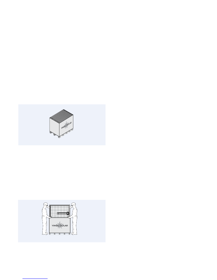
Transport and Handling
Yingli Solar PV modules must be transported in the supplied packaging only and
kept in the packaging until they are ready to be installed. Protect pallets against
movement and exposure to damage during transportation. Secure pallets from
falling over. Do not exceed the maximum height of pallets to be stacked, as
indicated on the pallet packaging. Store pallets in a cool and dry location until
the PV modules are ready to be unpackaged.
Figure 2: Pallet of PV modules
Yingli Solar PV modules are heavy, and should be handled with care. PV modules
shall be handled at the frame; never use the junction box or cables as a grip. Do
not exert mechanical stress on the cables. Never step on PV modules or drop
or place heavy objects on them. Be careful when placing PV modules on hard
surfaces, and secure them from falling. Broken glass can result in personal injury.
PV modules with broken glass cannot be repaired and must not be used. Broken
or damaged PV modules must be handled carefully and disposed of properly.
For unpacking PV modules from the Yingli Solar supplied packaging, first remove
the pallet lid (after removing securing straps, if provided). Remove PV modules
one at a time by sliding them up the channel in the package (see Figure 3). You
may need to secure the remaining PV modules in the pallet packaging to prevent
them from falling over.
Figure 3: Removing PV modules from a pallet
Check PV modules for damage due to transportation before they are installed;
do not install damaged modules. Contact the company you purchased the Yingli
Solar PV modules from in order to obtain information on making claims for
defective PV modules.
PV module surfaces are susceptible to damage that could affect the performance
or safety of the PV module; do not damage or scratch the PV module surfaces,
and do not apply paint or adhesive to any of the surfaces, including the frame.
For your safety, do not disassemble or modify Yingli Solar PV modules in any
way. Doing so may degrade performance or cause irreparable damage and will
void any applicable warranties.
If it is necessary to store PV modules prior to installation, the PV modules
should remain inside the packaging and protected from exposure that could
compromise the durability of the packaging.
Fire
Yingli Solar PV Modules have a Class C fire resistance rating in accordance with
the IEC 61730-2 certification. When PV modules are mounted on rooftops, the
roof must have a fire resistant covering suitable for this application. PV modules
are electrical generating devices that may affect the fire safety of a building.
The use of improper installation methods and/or defective parts may result
in the unexpected occurrence of an electrical arc during operation. In order to
mitigate the risk of fire in this event, PV modules should not be installed near
flammable liquids, gases, or locations with hazardous materials.
In the event of a fire, PV modules may continue to produce a dangerous voltage,
even if they have been disconnected from the inverter, have been partly or
entirely destroyed, or the system wiring has been compromised or destroyed. In
the event of fire, inform the fire crew about the particular hazards from the PV
system, and stay away from all elements of the PV system during and after a fire
until the necessary steps have been taken to make the PV system safe.
A P P L I C AT I O N I N F O R M AT I O N
Application Restrictions
Yingli Solar PV modules must be mounted on appropriate mounting structures
positioned on suitable buildings, the ground, or other structures suitable for PV
modules (e.g. carports, building facades or PV trackers). PV modules must not
be mounted on moving vehicles of any kind. Yingli Solar PV modules must not
be installed in locations where they could be submerged in water.
Yingli Solar PV modules must not be sited in locations where aggressive
substances such as salt or salt-water, or any other type of corrosive agent, could
affect the safety and/or performance of the PV modules. Although some types
of Yingli Solar PV modules have passed the IEC 61701 salt-mist corrosion test
with a salt concentration of 5% by weight, galvanic corrosion can occur between
the aluminum frame of the PV module and mounting or grounding hardware if
such hardware is comprised of dissimilar metals. Yingli Solar recommends that
only stainless steel and aluminum metal directly contact PV modules in seaside
installations to limit corrosion.
Artificially concentrated light must not be directed on Yingli Solar PV modules.
Design Recommendations
Yingli Solar recommends that PV modules be mounted at a minimum tilt angle
of 10 degrees to allow for proper self-cleaning from normal rain showers.
Partial or complete shading of a PV module or modules can significantly reduce
system performance. Yingli Solar recommends minimizing the amount of shade
throughout the year to increase the amount of energy produced by the PV
modules.
Lightning protection is recommended for PV systems that are to be installed in
locations with high probability of lightning strikes.
High system voltages could be induced in the event of an indirect
lightning
strike, which could cause damage to PV system components.
The open area of
wire loops should be minimized, as shown in Figure 4,
in order to reduce the risk
Series wiring (voltage additive)
Parallel wiring (current additive)
Fully engage and lock
Cap
+
–
Yingli Solar PV Modules, Installation and User Manual
page 4
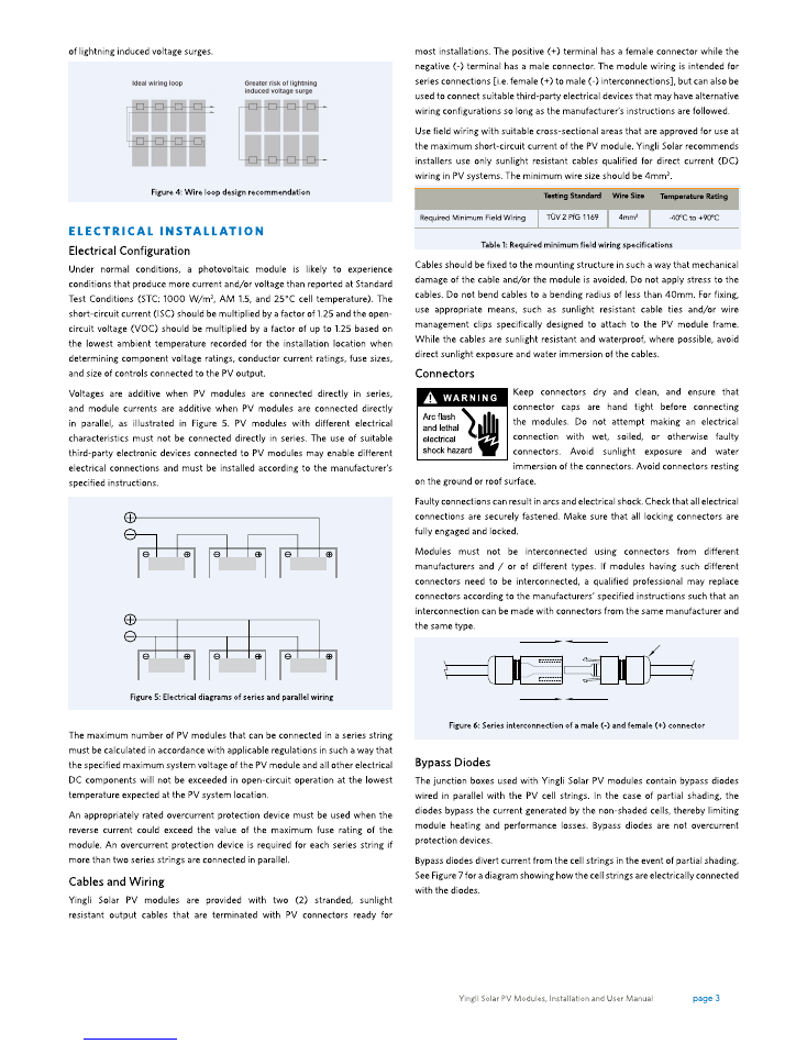
Figure 7: Electrical circuitry of cells and bypass diodes
In the event of a known or suspected diode failure, installers or maintenance
providers should contact the company the PV modules were purchased from.
Never attempt to open the junction box of a Yingli Solar PV module yourself.
PV Array Grounding
For optimal performance, Yingli Solar recommends that the negative pole of the
PV array be connected to ground.
Equipment Grounding
The frame of the PV module, as well as any exposed non-current-carrying metal
parts of fixed equipment that are able to become energized by the PV system,
must be connected to the equipment grounding conductor (EGC) in order to
prevent electrical shock. Even when applicable regulations, code requirements,
and standards do not require safety-related grounding, Yingli Solar recommends
grounding all PV
module frames in order to ensure the voltage between
electrically conductive equipment and earth ground is zero in all circumstances.
Proper equipment grounding is achieved by bonding all exposed non-current-
carrying metal equipment continuously to one another using an appropriately
sized EGC or racking system that can be used for integrated grounding (see
Option B in Grounding Methods below).
Yingli Solar PV modules employ a coated aluminum frame for corrosion
resistance. In order to properly ground the module frame, the coating must be
penetrated.
The potential for corrosion due to the electrochemical action between dissimilar
metals in contact is minimized if the electrochemical voltage potential between
the dissimilar metals is low. The grounding method must not result in the direct
contact of dissimilar metals with the aluminum frame of the PV module that
will result in galvanic corrosion. An addendum to UL Standard 1703 “Flat Plate
Photovoltaic Modules and Panels” recommends metal combinations not exceed
an electrochemical potential difference of 0.5 Volts.
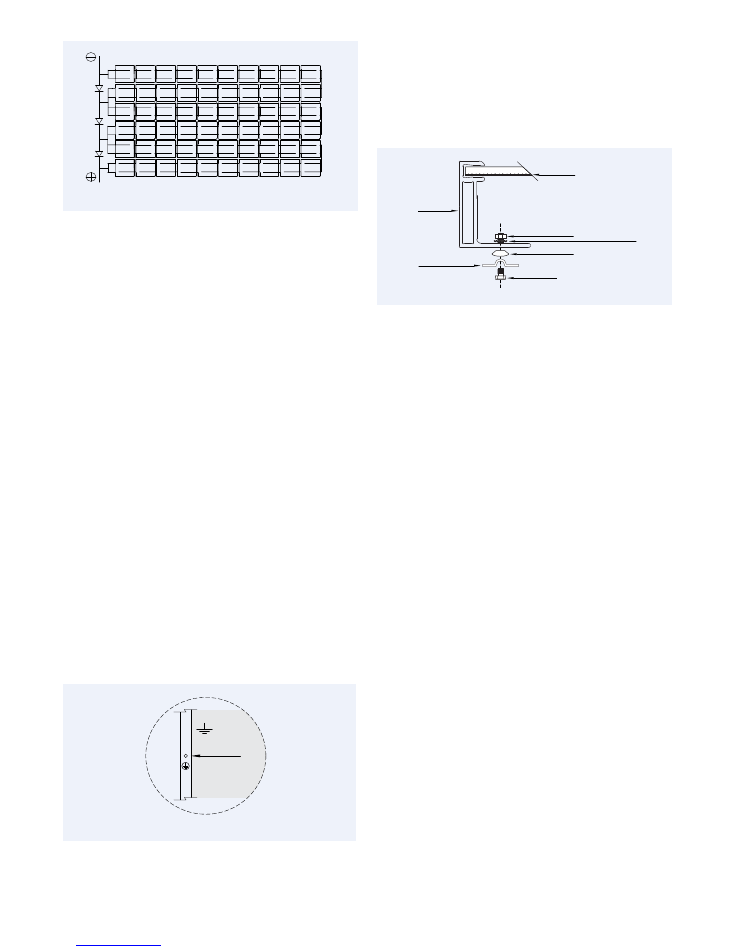
The frame rails have pre-drilled holes marked with a grounding sign, as
illustrated in Figure 8. These holes should be used for grounding
purposes and
must not be used for mounting the PV modules. Do not drill additional holes
into the frame rails.
Figure 8: Grounding hole detail
The following grounding methods are available:
Option A: Screw Assembly (see Figure 9)
1. A grounding screw assembly must be attached at a designated grounding
hole location using only stainless steel hardware. Insert an M5 stainless
steel screw first through the stainless steel cup washer, and then through the
grounding hole.
2. Loosely engage a stainless steel backing nut and toothed lock washer to the
screw.
Figure 9: Grounding screw assembly detail
3. Bend the EGC into an omega (Ω) shape to tightly fit between the partially
installed screw head and cup washer. The EGC shall be exclusively in contact
with stainless steel.
4. Tighten the screw to 2.3 N∙m torque. The toothed lock washer should be
visibly engaged to the frame.
5. Route the appropriately sized EGC in such a way as to avoid contact with the
aluminum module frame.
Option B: Racking Manufacturer Integrated
Grounding Methods
Yingli Solar PV modules can be grounded by bonding PV modules to a grounded
racking system. Integrated grounding methods must be certified for grounding
PV modules and must be installed in accordance with the specified instructions
of their respective manufacturers.
option c: additional Third-party grounding Devices
Yingli Solar PV modules can be grounded using third party grounding devices so
long as they are certified for grounding PV modules and the devices are installed
according to the manufacturer’s specified instructions.
M E C H A N I C A L I N S TA L L AT I O N
General
Yingli Solar PV Modules have been certified for a maximum static load on the
back of the module of up to 2400 Pa (i.e. wind load) and a maximum static load
on the front of the module of up to either 2400 Pa or 5400 Pa (i.e. wind and
snow load), depending on the module type (please refer to the data sheet for
this information).
Mounting structures and other mechanical parts must be designed and approved
to withstand the design wind and snow loads applicable for a particular site.
Yingli Solar PV modules must not be subjected to forces from the substructure,
including forces caused by thermal expansion.
The mounting method must not result in the direct contact of dissimilar
metals with the aluminum frame of the PV module that will result in galvanic
corrosion. An addendum to UL Standard 1703 “Flat Plate Photovoltaic Modules
and Panels” recommends metal combinations not exceed an electrochemical
potential difference of 0.5 Volts.
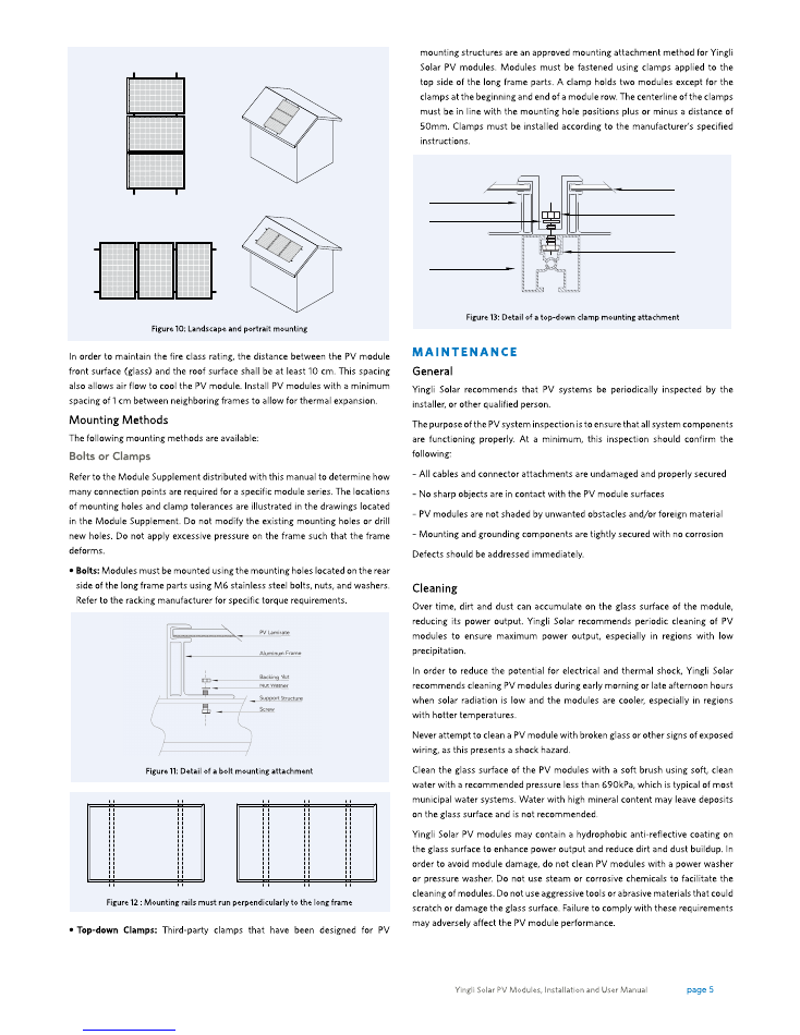
Yingli Solar PV modules can be mounted in landscape or portrait orientation, as
illustrated in Figure 10, provided that the mounting method follows one of the
acceptable methods listed below.
Grounding Holes
ø0.236in (6mm)
PV Laminate
Backing Nut
Toothed Lock Washer or KEPS Nut
Cup Washer
Aluminum
Frame
Screw
Equipment
Grounding
Conductor
Landscape Orientation
Portrait Orientation
Screw
Backing Nut
Nut Washer
PV Laminate
Mounting Rail
Aluminum Frame

Yingli Solar PV Modules, Installation and User Manual
page 6
Yingli Solar PV modules are designed to withstand high snow loads. However, if
removing snow is desired to enhance production, use a brush to gently remove
snow. Do not try to remove frozen snow or ice from PV modules.
D E CO M M I S S I O N I N G
The dismantling of PV systems must be performed with the same care and
safety precautions used during the initial installation. The PV system can
generate hazardous voltage even after the system has been disconnected.
Follow safety regulations for working with live electrical equipment.
R E C YC L I N G
Yingli Solar is a member of PV Cycle, the European association for voluntary
take back and recycling of PV modules. Please contact PV Cycle at www.
pvcycle.org for details regarding the recycling process.
© Yingli Green Energy Holding Co. Ltd.
InstallationManual_IEC_EN_20160419_V03
YINGLISOLAR.COM
NYSE:
YGE
Yingli Green Energy Holding Co., Ltd.
service@yingli.com
Service hotline:+86-312-2188055
Complaints hotline:+86-312-8922216
Yingli Solar PV Modules, Installation and User Manual
page 7
The information in this supplement is believed to be reliable, but does not constitute an expressed or implied warranty. Yingli Solar reserves the right to make
changes to its PV modules and other products, their specifications, or this supplement without prior notice.
This supplement to the installation manual does not contain information about some older module series no longer being manufactured by Yingli Solar. If you require
information about such modules, please contact Yingli Solar.
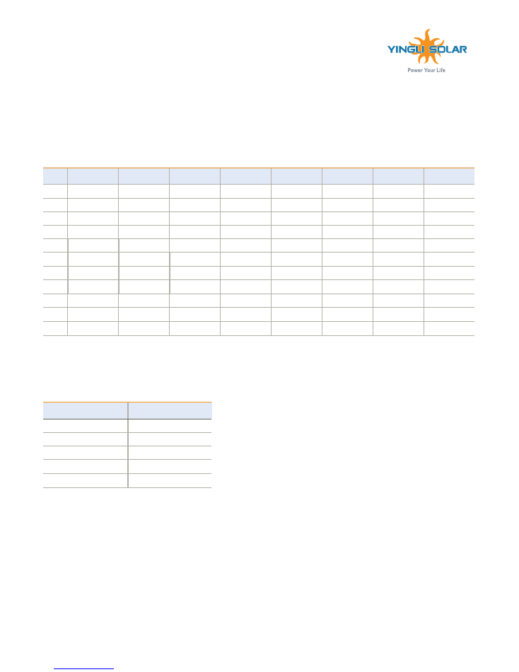
This supplement refers to modules of the following types:
Table 1: Module types
FAMILY
YGE 60 Cell Series 2
YGE 72 Cell Series 2
PANDA 50 Cell
Series
PANDA 60 Cell
Series 2
PANDA 72 Cell
NH Series
YLM 50 Cell
Series
YLM 60 Cell
40mm Series
YLM 72 Cell 40mm
Series
TYPE
YL250P-29b
YL300P-35b
YL220C-25b
YL260C-30b
YL310C-36b
YL215D-25b
YL260D-30b
YL315D-36b
YL255P-29b
YL305P-35b
YL225C-25b
YL265C-30b
YL315C-36b
YL220D-25b
YL265D-30b
YL320D-36b
YL260P-29b
YL310P-35b
YL230C-25b
YL270C-30b
YL320C-36b
YL225D-25b
YL270D-30b
YL325D-36b
YL265P-29b
YL315P-35b
YL235C-25b
YL275C-30b
YL325C-36b
YL230D-25b
YL275D-30b
YL330D-36b
YL270P-29b
YL320P-35b
YL240C-25b
YL280C-30b
YL330C-36b
YL235D-25b
YL280D-30b
YL335D-36b
YL275P-29b
YL325P-35b
YL245C-25b
YL285C-30b
YL335C-36b
YL240D-25b
YL285D-30b
YL340D-36b
YL280P-29b
YL330P-35b
YL250C-25b
YL290C-30b
YL340C-36b
YL345D-36b
YL285P-29b
YL335P-35b
YL295C-30b
YL345C-36b
YL290P-29b
YL340P-35b
YL300C-30b
YL350C-36b
YL345P-35b
YL355C-36b
YL350P-35b
YL360C-36b
YINGLI SOLAR PV MODULES
Module Supplement
Revision Date July 20th
,
2016 | Applicable for IEC certified products.
File name: Corporate Logo with Tagline / Vertical.ai
M O U N T I N G R E Q U I R E M E N T S
Mounting Method: Bolts and Clamps
Table 2: Mounting requirements
Modules that Require
Four (4) Connection Points
Modules that Require
Six (6) Connection Points
YGE 60 Cell Series 2
YGE 72 Cell Series 2
PANDA 50 cell series
PANDA 72 Cell NH Series
PANDA 60 Cell Series 2
YLM 72 Cell 40mm Series
YLM 50 cell series
YLM 60 Cell 40mm Series
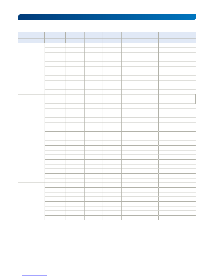
E L E C T R I C A L C H A R AC T E R I S T I C S
Nameplate ratings are average values. The electrical characteristics are within +/- 10 percent of the indicated values of Isc, Voc, and Pmax under Standard Test
Conditions (irradiance of 1000 W/m
2
, AM 1.5 spectrum, and a cell temperature of 25°C). Refer to module datasheets for specific power output tolerances. Note that
not necessarily all power classes are available for all module series given in the first column of Table 3. Please refer to Table 1 to see which power classes actually
exist for which module series.
Yingli Solar PV Modules, Installation and User Manual
page 8
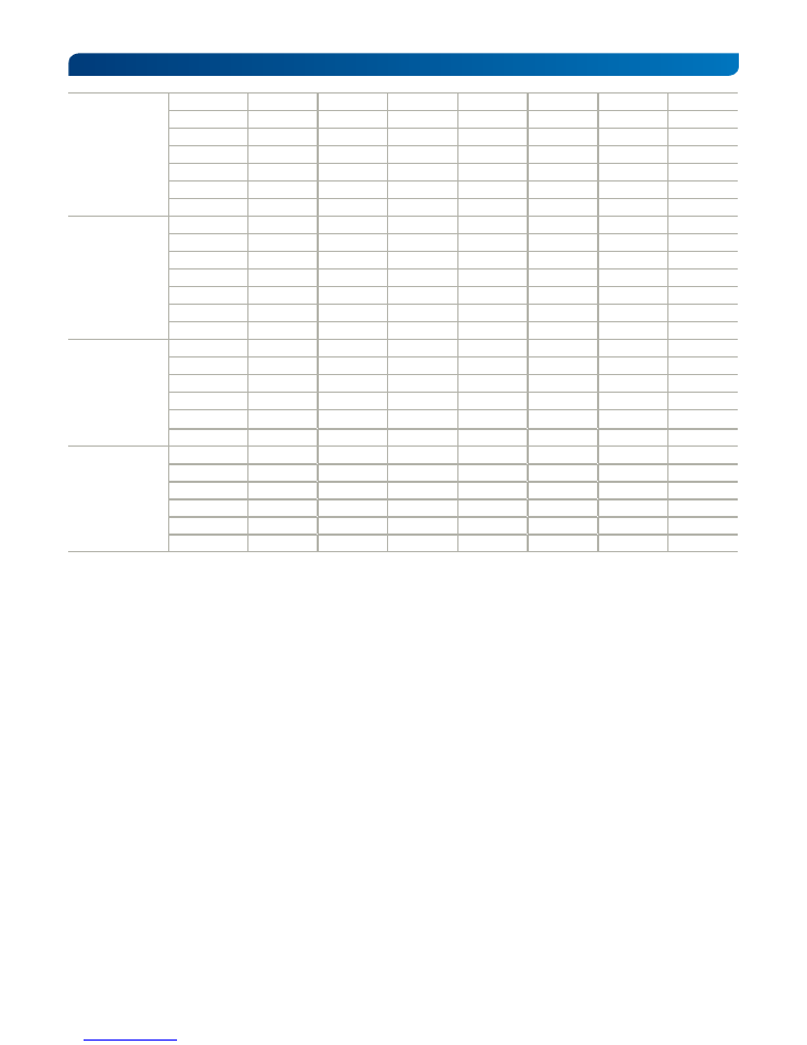
Table 3: Electrical characteristics
Series
Module
P
max
V
mpp
I
mpp
V
oc
I
sc
Max. system
voltage
Max. series fuse
rating
[W]
[V]
[A]
[V]
[A]
[V]
[A]
YGE 72 Cell Series 2
YL350P-35b
350
47.2
9.51
38.2
9.17
1000
15
YL345P-35b
345
47.0
9.45
38.0
9.08
1000
15
YL340P-35b
340
46.7
9.40
37.8
9.00
1000
15
YL335P-35b
335
46.7
9.34
37.6
8.91
1000
15
YL330P-35b
330
46.4
9.29
37.4
8.84
1000
15
YL325P-35b
325
46.3
9.24
37.3
8.72
1000
15
YL320P-35b
320
37.0
8.64
46.0
9.18
1000
15
YL315P-35b
315
36.8
8.56
45.7
9.12
1000
15
YL310P-35b
310
36.3
8.53
45.6
8.99
1000
15
YL305P-35b
305
36.1
8.45
45.4
8.93
1000
15
YL300P-35b
300
35.8
8.37
45.2
8.86
1000
15
YGE 60 Cell Series 2
YL290P-29b
290
38.6
9.65
31.9
9.12
1000
15
YL285P-29b
285
38.4
9.55
31.6
9.02
1000
15
YL280P-29b
280
38.2
9.45
31.4
8.92
1000
15
YL275P-29b
275
37.9
9.35
31.0
8.90
1000
15
YL270P-29b
270
37.9
9.27
30.7
8.80
1000
15
YL265P-29b
265
30.5
8.70
37.8
9.18
1000
15
YL260P-29b
260
30.3
8.59
37.7
9.09
1000
15
YL255P-29b
255
30.0
8.49
37.7
9.01
1000
15
YL250P-29b
250
29.8
8.39
37.6
8.92
1000
15
PANDA 72 Cell
NH
Series
YL360C-36b
360
40.2
8.95
47.8
9.27
1000
15
YL355C-36b
355
39.8
8.92
47.6
9.26
1000
15
YL350C-36b
350
39.4
8.89
47.4
9.26
1000
15
YL345C-36b
345
39.0
8.85
47.2
9.26
1000
15
YL340C-36b
340
38.5
8.82
47.0
9.25
1000
15
YL335C-36b
335
38.1
8.79
46.8
9.25
1000
15
YL330C-36b
330
37.7
8.76
46.6
9.25
1000
15
YL325C-36b
325
37.3
8.72
46.4
9.24
1000
15
YL320C-36b
320
36.8
8.69
46.2
9.24
1000
15
YL315C-36b
315
36.4
8.65
46.0
9.23
1000
15
PANDA 60 Cell Series 2
YL300C-30b
300
32.7
9.16
40.1
9.66
1000
15
YL295C-30b
295
32.4
9.11
39.9
9.62
1000
15
YL290C-30b
290
32.0
9.06
39.6
9.58
1000
15
YL285C-30b
285
31.6
9.01
39.4
9.54
1000
15
YL280C-30b
280
31.3
8.96
39.1
9.5
1000
15
YL275C-30b
275
30.9
8.91
38.8
9.47
1000
15
YL270C-30b
270
30.5
8.85
38.6
9.43
1000
15
YL265C-30b
265
30.1
8.79
38.3
9.37
1000
15
Yingli Solar PV Modules, Installation and User Manual
page 9
PANDA 50 Cell Series
YL250C-25b
250
27.6
9.06
33.3
9.73
1000
15
YL245C-25b
245
27.3
8.97
33.1
9.62
1000
15
YL240C-25b
240
26.9
8.92
32.9
9.50
1000
15
YL235C-25b
235
26.5
8.87
32.6
9.41
1000
15
YL230C-25b
230
26.1
8.81
32.4
9.34
1000
15
YL225C-25b
225
25.8
8.72
32.2
9.15
1000
15
YL220C-25b
220
25.6
8.59
32.0
9.03
1000
15
YLM 72 Cell 40mm
Series
YL345D-36b
345
38.3
9.02
47.7
9.38
1000
15
YL340D-36b
340
37.9
8.97
47.3
9.35
1000
15
YL335D-36b
335
37.6
8.91
46.9
9.32
1000
15
YL330D-36b
330
37.2
8.86
46.6
9.29
1000
15
YL325D-36b
325
36.9
8.81
46.2
9.27
1000
15
YL320D-36b
320
36.6
8.75
45.9
9.24
1000
15
YL315D-36b
315
36.2
8.69
45.5
9.21
1000
15
YLM 60 Cell 40mm
Series
YL285D-30b
285
31.7
9.00
39.6
9.41
1000
15
YL280D-30b
280
31.4
8.91
39.3
9.38
1000
15
YL275D-30b
275
31.2
8.82
38.9
9.34
1000
15
YL270D-30b
270
30.9
8.73
38.6
9.31
1000
15
YL265D-30b
265
30.7
8.64
38.3
9.27
1000
15
YL260D-30b
260
30.4
8.56
38.0
9.24
1000
15
YLM 50 Cell Series
YL240D-25b
240
27.1
8.87
32.9
9.41
1000
15
YL235D-25b
235
26.7
8.81
32.5
9.38
1000
15
YL230D-25b
230
26.3
8.75
32.1
9.34
1000
15
YL225D-25b
225
25.9
8.69
31.7
9.31
1000
15
YL220D-25b
220
25.5
8.63
31.3
9.27
1000
15
YL215D-25b
215
25.1
8.57
31.0
9.24
1000
15
Yingli Solar PV Modules, Installation and User Manual
page 10
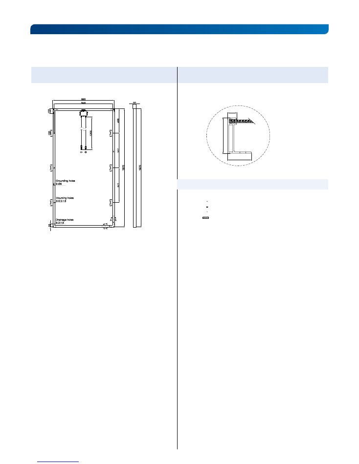
R E A R A N D S I D E V I E W D I M E N S I O N S O F M O D U L E S E R I E S W I T H 5 0 M M F R A M E
UNITS: mm
PANDA 72 Cell
NH
Series
Frame Cross Section
12
32
50
SECTION A–A
Frame P Cross Section A-A
Legend
Legend
Grounding holes
Mounting holes
Drainage holes
Mounting tolerance
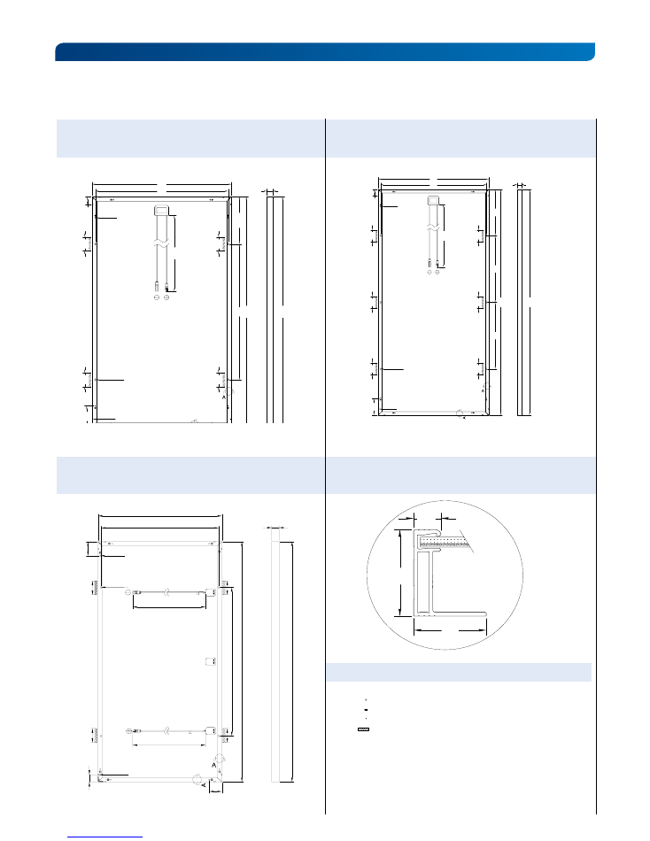
Yingli Solar PV Modules, Installation and User Manual
page 11
PANADA 50 Cell Series Frame Cross Section
(also valid for YLM 50Cell Series)
12
40
32
SECTION A-A
Legend
Legend
Grounding holes
Mounting holes
Drainage holes
Mounting tolerance
PANDA 60 Cell
Series2
YGE 72 Cell Series 2
(also valid for YLM 60Cell 40mm Series)
(also valid for YLM 72Cell 40mm Series)
R E A R A N D S I D E V I E W D I M E N S I O N S O F M O D U L E S E R I E S W I T H 4 0 M M F R A M E ( CO N T. )
UNITS: mm
1100
946
990
1960
150
55
A
A
403
40
1960
577
577
Grounding holes
8-
Φ
6
Mounting holes
6-6.5
×
8
Drainage holes
8-3
×
8
100
100
100
100
100
100
10
00
946
990
967 16
40
150
55
Drainage holes
8-3
×
8
Mounting holes
4-6.5
×
8
Grounding holes
8-
Φ
6
A
A
336.5
40
16
40
100
100
100
100
+
-
40
1
640
1
640
806
850
1
030
Mounting holes
4-6.5
×
8
Drainage holes
8-3
×
8
55
10
0
Grounding holes
8-Ø6
A
A
1000
1000
100
10
0
Yingli Solar PV Modules, Installation and User Manual
page 12
© Yingli Green Energy Holding Co. Ltd.
Module Supplement_IEC_EN_20160720_V03
YINGLISOLAR.COM
NYSE:
YGE
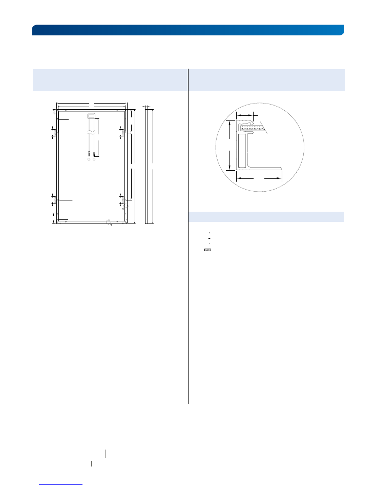
YGE 60 Cell Series 2 Frame Cross Section
R E A R A N D S I D E V I E W D I M E N S I O N S O F M O D U L E S E R I E S W I T H 3 5 M M F R A M E
UNITS: mm
1000
946
990
967 1640
150
55
Drainage holes
8-3
×
8
Mounting holes
4-6.5
×
8
Grounding holes
8-
Φ
6
A
A
336.5
35
1640
100
100
100
100
Legend
12
35
32
SECTION A-A
Legend
Grounding holes
Mounting holes
Drainage holes
Mounting tolerance
Yingli Green Energy Holding Co., Ltd.
service@yingli.com
Service hotline:+86-312-2188055
Complaints hotline:+86-312-8922216