Full Text Searchable PDF User Manual

1
© Wilks-USA
TX750 / TX750i
1
READ THIS MANUAL CAREFULLY BEFORE USE – FAILURE TO DO SO MAY RESULT IN INJURY, PROPERTY
DAMAGE AND MAY VOID WARRANTY. • KEEP THIS MANUAL FOR FUTURE REFERENCE. • Products covered by
this manual may vary in appearance, assembly, inclusions, specifications, description and packaging.
V 1.0
Gasoline Pressure Washer
TX750 . TX750i

2
© Wilks-USA
TX750 / TX750i
Contents
02 -
Contents
03 -
General Safety Instructions
04 -
Explanation of the symbols used in this Manual
05 -
Maintenance and Storage
Getting to know your petrol washer
06 -
Assembly
07 -
Operation and Use
08 -
Water Supply from the Water Mains
09 -
Adjusting the Spray Pattern
10 -
Using the Detergent Facility
Clearing a Blockage
Safety Instructions for the Engine
11 -
Pre-Operation Inspection
12 -
Fuel and Fuel Tank
Fuel Tank Filter
Oil Level Switch
Air
Filter
13 - Storage
Winter and Long Term Storage
14 -
Maintenance
Exhaust Control System
Maintenance
Replacement of Parts
Modifying
Problems Affecting Exhaust Emissions
Water Suction Filter Checking
15 -
Spark Plug Maintenance
Carburettor Idling Adjustment
16 - Transport
Storage
Prepare for Storage
17 -
Removal Fom Storage
Service Schedule
Engine Oil Replacement
18 -
Service Schedule Table
19 -
Troubleshooting
20 - Troubleshooting
21 -
Pump Parts Diagram
22 -
CE Declaration of Conformity
3
© Wilks-USA
TX750 / TX750i
General Safety Instructions
•
GENERAL SAFETY INSTRUCTIONS
•
Read instructions carefully before operating this product.
•
Keep bystanders away.
•
This product is for outdoor use only.
•
Ensure the engine is stopped before carrying out adjustments, cleaning or maintenance.
•
Always turn off the engine and water supply when finished.
•
Do not use the product if found to be damaged.
•
Only use with detergents specified by the manufacturer. Other chemicals may compromise the safety of the product.
•
Do not direct the pressure jet towards mechanical parts containing lubricant grease. ■
•
Clean vehicle tyres from a minimum of 50cm to avoid damage by the high pressure jet. ■
•
Do not point high pressure jets at people, animals, live electrical parts or the product itself. ■
•
Do not use accessories such as hoses and connections that are not advised by the manufacturer.
•
Engage the high pressure safety catch located on the gun when not in use. ■
•
Do not step/stand on the high pressure hose.
•
Ensure the nozzle is securely attached before using the Product. High pressure can cause it to be fired from the lance
with considerable force, and could cause injury damage. ■
•
Be ready for the kick-back force and the sudden torque on the spray assembly when operating the trigger.
•
A high pressure jet can remove paint and other surface finish. It can also damage tarmac and grouting.
•
Switch off completely when not attended.
•
The hose is designed specifically for operation with high pressures. Take care to avoid damage that may prevent
correct operation of the product.
•
This product is not to be used by children or anyone with reduced capabilities.
•
Always completely unwind the high pressure hose prior to operation.
•
Make sure that the machine is switched off before unwinding the high pressure hose, and take care not to pull the
machine over.
•
Do not let the high pressure hose contact the hot engine exhaust.
•
Do not use this product indoors.
•
Keep exhaust emissions away from air intakes.
3
4
© Wilks-USA
TX750 / TX750i
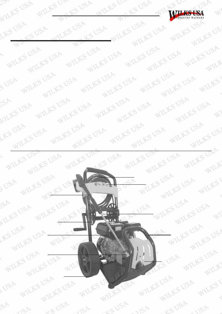
Explanation of the symbols used in this Manual
Technical Paramaters
Warning! Read the operating
Instructions before use!
Wear hearing protection!
Warning! Do not inhale exhaust fumes
Wear safety goggles!
Attention! Hot surfaces! Risk of burns!
High-pressure jets can be dangerous
if misused. Do not aim at animals,
electrical appliances or the machine itself.
Wear protective gloves
Warning! Risk of injury. Pay special attention
Wear safety shoes
Caution! Be aware of potential risks/hazards
Model
TX675
TX700
TX725
TX750
Max Pressure
13Mpa (1885 PSI)
17Mpa (2465 PSI)
18Mpa (2610 PSI)
27Mpa (3950 PSI)
Continuous
Pressure
10Mpa (1450 PSI)
15Mpa (2175 PSI)
16Mpa (2320 PSI)
22Mpa (3200PSI)
Max Flow Rate
9.2L/min
9.2L/min
9.2L/min
10L/min
Engine
2.5-4 HP
5.5 HP
6.5 HP
8 HP
Rated Rotation
Speed
3400 RPM
3400 RPM
3400 RPM
3400 RPM
Allowable
Temperature
0-60ºC
0-60ºC
0-60ºC
0-60ºC
5
© Wilks-USA
TX750 / TX750i
•
Do not attempt to modify the product In any way.
•
To ensure good operating conditions, range regular service from an authorized agent.
•
Only use replacement parts supplied by the manufacturer.
•
Only use fresh, clean and good quality fuel in the engine.
•
Never operate the engine without oil.
•
Never refuel in close proximity to naked flames, sparks or other sources of ignition e.g. cigarettes.
•
Do not refuel when the engine it hot.
•
Wipe up and correctly dispose of any fuel spillage immediately within public guidelines.
•
Move away from the refuelling areas before restarting the engine. Store fuel for short periods only in a suitable
container away from heat and direct sunlight.
•
Clean the pressure washer thoroughly after each use.
•
Regularly check external nuts and fixings to ensure vibration caused by normal caused y normal use has not loosened
them. Remove the spark plug ignition lead (HT Lead) from the back of the spark plug and position the lead to avoid
accidental reconnection.
•
Store the machine in a secure dry location out of reach of children.
•
Empty the fuel lank before storage.
Maintenance and Storage
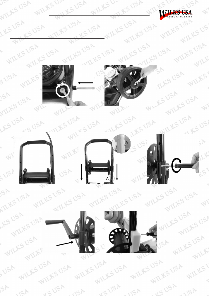
Getting to Know Your Petrol Washer
Fuel Tank
Lance Nozzle End
Wheels
Hose Reel (TX750i)
Gun/Lance
Spare Hose
Nozzle Storage
Lance Extension
Lower Frame
Detergent Tank
6
© Wilks-USA
TX750 / TX750i
Note: Every Machine is tested during production, so there may be a few drops of water inside the pump
assembly
Assembly
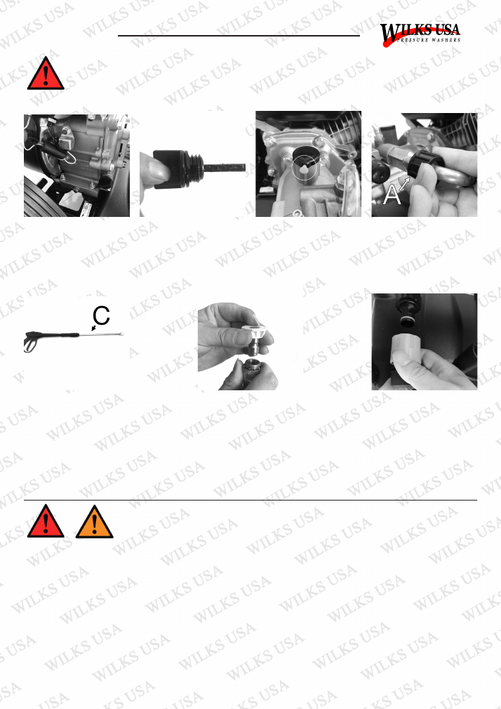
To assemble the wheels (figs 1-2)
Insert the axle in to the axle tube
at the bottom of the frame, then
fix with M6 screws.
Fig.01
Fig.02
Assemble the wheel on the axle
and fix it with a nut.
In the direction of the arrow, fix
the hose reel on the frame (TX750i
only)
Fig.03
Fig.04
Fig.05
Fig.06
Fig.07
In the direction of the arrow, insert
the handle of the frame into the
frame, lock it by lock catch A.
In order to avoid the hose reel
moving, fix it with screw and nut
In the direction of the arrow, insert
the handle into the mounting hole
of the hose reel.
Assemble the panel as shown.
7
© Wilks-USA
TX750 / TX750i
Operation and Use
Warning:
The engine is not filled with oil. It is necessary to fill the unit before starting the engine. The engine
will not product a spark unless sufficient oil is inside.
Caution:
Do not run the engine with high or low oil level as this can cause engine damage.
Caution:
Only use unleaded gasoline.
Caution:
Avoid damaging your hose by ensuring it does not touch the hot exhaust during or after use.
Caution:
Avoid damaging your pump by ensuring the water supply is clean and free of any foreign objects
Caution:
Inlet water temperature must not exceed 40ºC and 20 PSI
Caution:
Never let the appliance operate for more than 2 minutes with the spray gun in the closed position
Caution:
Never operate the pressure washer with repeated and rapid on/off movements of the trigger
WARNING: The engine is not provided with oil. It is necessary to fill the unit before starting the
engine.
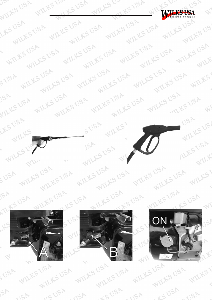
Fig.08
Engine Oil. (fig.08-09) Warning:
The engine is not provided
with oil. It is necessary to fill the unit before starting the engine.
The engine has two oil fill points at the front and back of the
engine. Remove the desired cap and fill with the engine oil
specified to the upper level mark or base of threads.
Fig.09
Pump Oil. (fig.10) Warning:
The YELLOW pin must be
removed from the RED
breather plug before use.
High Pressure Connection
(fig.11-14):
Connect the
high pressure hose A to the
units high pressure outlet.
Fig.10
Fig.11
Connect the High Pressure
Hose to the Trigger B:
Insert
the lance C into the gun
end. Press firmly and twist
the coupling into the locked
position.
Fig.12
Connecting the Hose:
Connect the hose to the
water inlet connector (MAX.
20PSI, MAX 40°C Temp)
and turn the water on
completely.
Fig.14
Inserting a Nozzle (fig.13):
To insert a nozzle, pull back
the locking collar at the end
of the lance, insert nozzle
and release the collar. This
will lock the nozzle in place.
Ensure the nozzle is inserted
correctly. If not it can fly
out and injure personnel or
damage property.
Fig.13
8
© Wilks-USA
TX750 / TX750i
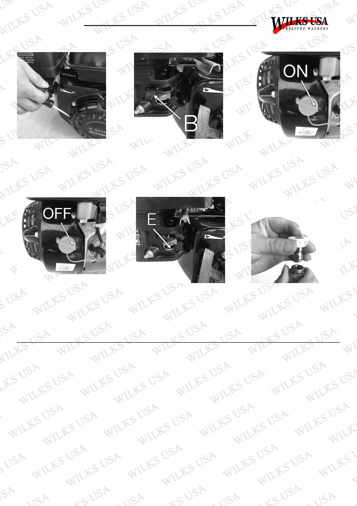
Pull the trigger to eliminate
trapped air and wait for a steady
flow of water to emerge from the
spray nozzle.
NOTE: In order to assist further
setup it is recommended to press
the trigger during the pulling of
recoil start handle.
Fig.15
To prevent accidental operation
the trigger is fitted with a locking
facility.
Fig.16
Starting the Engine (fig.17-20):
Push the fuel lever A to the right
(ON position)
Fig.17
Fig.18
Fig.19
Push the Choke lever B to the left;
closing the Choke for initial start-
up.
NOTE:
Do not use the Choke
if the engine or air temperature is
warm.
Turn the engine switch clockwise
to the ON Position.
•
Connect a water supply hose (not supplied) to the water inlet connection of the pressure washer
•
Turn on the water supply and pull the trigger until water is continually flowing out of the nozzle.
WATER SUPPLY FROM A CONTAINER / STANDING WATER
•
Unscrew the coupling part for the water inlet.
•
Screw the suction hose with filter (not Included) onto the water connection of the unit.
•
Hang the filter in the container.
•
Vent the unit before operation.
•
Unscrew the high pressure line at the high pressure outlet of unit.
•
Switch on the unit and let it run until water is free of bubbles at the high pressure outlet.
•
Switch off the unit and screw on high pressure hose again.
Water Supply from the Water Mains
9
© Wilks-USA
TX750 / TX750i
You have a choice of 5 different colour coded nozzles giving you different spray patterns/pressures to choose
from. See fig.25
0º Nozzle (Red)
This nozzle delivers a pinpoint stream and is extremely powerful. It covers only a small area for
cleaning. The nozzle should only be used on surfaces which can withstand the high pressure such as metal/
concrete.
15º Nozzle (Yellow)
This nozzle delivers a powerful 15 degree spray for intense cleaning of small areas. The
nozzle should only be used on surfaces which can withstand the high pressure
25º Nozzle (Green)
This nozzle is used where high pressure is still required, over a medium sized area.
Produces more power than White nozzle in a smaller area.
40º Nozzle (White)
This nozzle a less focused spray pattern, giving a wider area of cleaning with less power.
This is used for most cleaning applications
Low Pressure Nozzle (Black)
This is used for chemical application only. The nozzle created the required back
pressure to draw detergent from the tank.
Adjusting the Spray Pattern
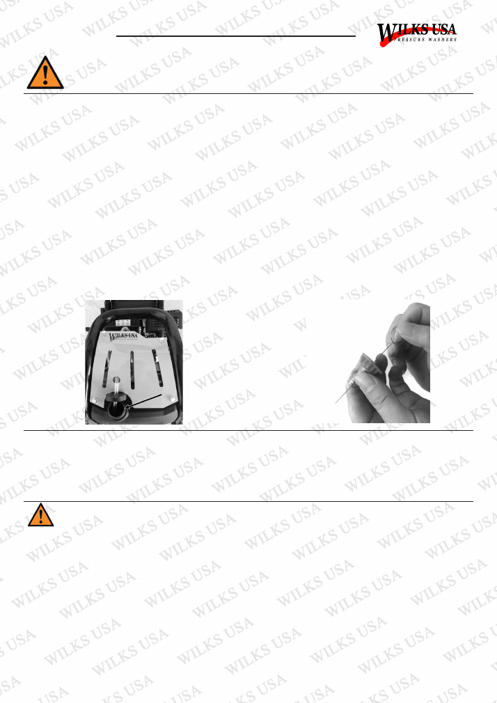
Pull the black handle on the Recoil
Starter gradually until you feel
resistance; then make a rapid pull
Fig.20
Fig.21
Fig.22
Push the Choke lever B to the left;
closing the Choke for initial start-
up.
NOTE:
Do not use the Choke
if the engine or air temperature is
warm.
Turn the engine switch clockwise
to the ON Position.
Stopping the engine (fig. 23-24)
In an emergency turn the engine
switch anticlockwise to the OFF
position to stall the engine. To
stop the appliance normally, use
the following sequence:
Fig.23
Turn the engine switch
anticlockwise to the OFF position.
Then slide the fuel lever E to the
right OFF position. Caution: When
you have finished working, turn off
the engine. When the machine is
switched off, always discharge the
pressure by depressing the trigger
Fig.24
Attaching a nozzle to the quick-fit
end of the lance.
Fig.25
10
© Wilks-USA
TX750 / TX750i
Fill a suitable container with pressure washer detergent. Do not use washing up liquid as it contains salt. Please
follow the instructions on the container. Most automobile detergents are a combination of detergent and a wax
solution. Viscosity (thickness) of the detergent will increase in cold weather. It is recommended that this type of
detergent is diluted with water before filling the container. When using combination was and wax solutions, we
recommend that they are diluted before use. As a general guide we would recommend a dilution rate of 50/50.
Please follow the instructions of your detergent product for variations/specific requirements.
Note:
A thick viscous detergent will not flow freely from the detergent tank and the residue is likely to cause a
blockage in the system. After using the detergent facility it should be flushed thoroughly with clean water
to remove ANY trace of detergent. To activate detergent facility, fit the BLACK nozzle to the end of the lance.
Submerge the end of the detergent tank inlet hose in the container/solution. Suction and mixing will occur as
water flows through the pump. You may be required to fit the shorter of the supplied hoses in conjunction with
the black nozzle to create the required pressure to draw detergent.
Using the Detergent Facility
Before using the pressure washer to clean patio paving slabs it is advisable to test a small area first
as some paving slabs are manufactured from inferior materials and the use of a pressure washer
could damage the surface
If at any time the flow rate stutters or is inconsistent, release the trigger and switch OFF the machine. Squeeze
the trigger to release any pressure and check the jet end of the lance for any blockage. If a blockage is
suspected, use some wire (supplied to rear of instruction manual) to clean inside the nozzle.
Clearing a Blockage
Safety Instructions for the Engine
1. Before operating the engine, be sure to read all instructions carefully as injury or permanent damage to the
machine may occur.
2. Run the engine in a well ventilated area.
3. Ensure the appliance is at least 1 metre away from building walls or other equipment.
4. Keep the appliance away fro flammable liquids such as petrol.
5. Refuel in a well ventilated area with the engine switched off and avoid sparks or naked flames.
6. When refuelling, ensure that you do not over fill the tank.
7. If any fuel is spilled ensure it is cleaned up thoroughly before restarting.
8. Ensure the fuel cap is located securely.
9. The exhaust mufflers get very hot and will remain hot for some time after the engine is switched off.
10. Ensure the appliance is completely cooled before transporting or storing.
Fig.26
Fig.27
11
© Wilks-USA
TX750 / TX750i
Engine oil is a key factor in deciding the engine’s performance. Do not use engine oil with additives or 2-stroke
gasoline engine oil as they do not have sufficient lubricating properties, which may shorten the engine’s service
life.
1. Check the engine is on level ground.
2. 10W-40 to 15W-30 is recommended for general all-temperature use.
3. Remove Dipstick and clean it.
(fig.28)
4. Re-insert the Dipstick into the oil filler port without screwing it in, lift out to check oil level.
5. If the oil level is too low, add the required amount of engine oil to the oil filler mark or to the lowest thread.
6. Replace the Dipstick securely.
Pre-Operation Inspection
Running with insufficient engine oil may damage the engine severely.
Caution
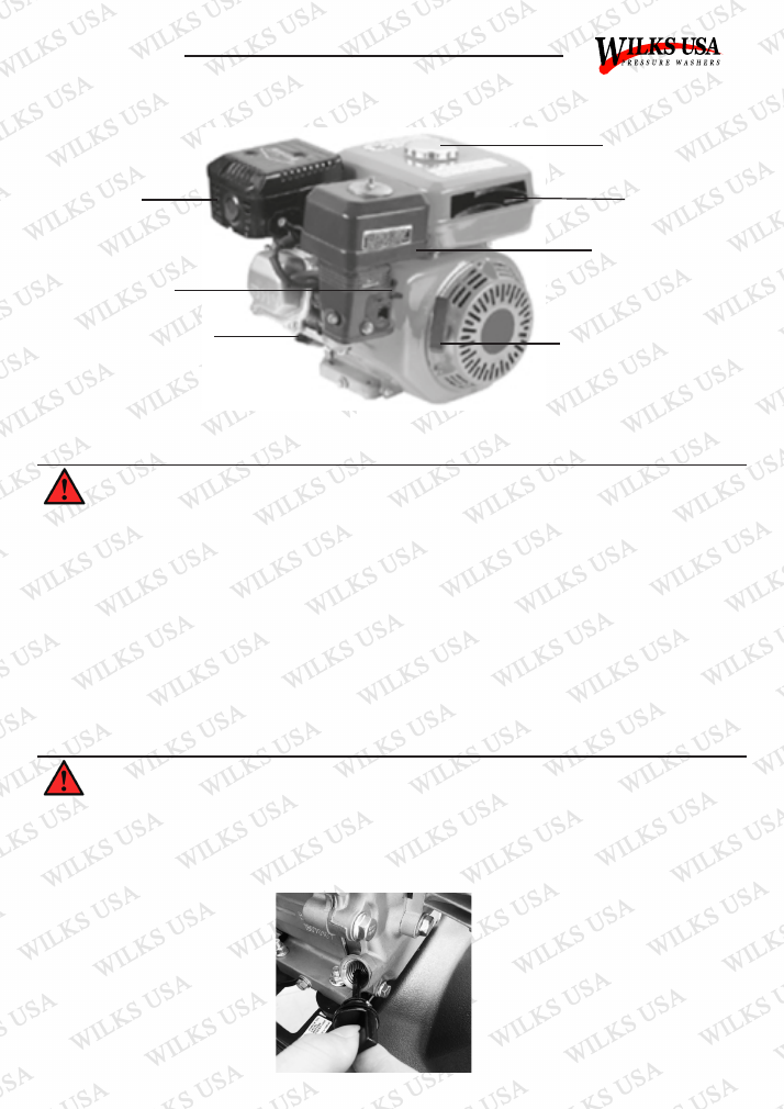
Exhaust
Choke Lever
Dipstick
Fuel Tank Cap
Fuel Tank
Air Filter
Recoil Starter Handle
Fig.28
12
© Wilks-USA
TX750 / TX750i
Fuel and Fuel Tank
Only use unleaded petrol or fuel with an octane number over 86. Using unleaded petrol or fuel will decrease the
possibility of producing carbon deposits and extend the engines service life. Never use old or polluted petrol or
fuel or a mixture of petrol and engine oil. Make sure the fuel is free of dirt and water.
Handle fuel with care because it can damage plastic and painted surfaces. Remove the fuel filler cap and check
the fuel level. If the fuel level is too low, refuel the tank taking care not to over fill.
Caution
Petrol is extremely flammable and is explosive under certain conditions. Refuel in a well ventilated area with
the engine stopped. Do not smoke or allow naked flames or sparks in the area where petrol is stored or where
refuelling is taking place. After refuelling, make sure the tank filler cap is returned securely. Be careful not to
spill the fuel when refuelling. Spilled fuel or vapour may ignite. If any fuel is spilled make sure the area is dry
before starting the engine.
Warning
After every 150 hours of running or every three months, the fuel tank filter should be removed and cleaned.
Remove the fuel tank filler cap and filter, clean thoroughly using environmentally friendly water based de-
greasing agent and re-fit.
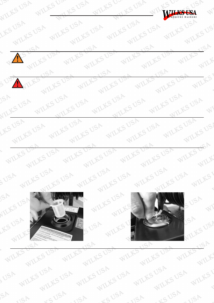
Fuel Tank Filter (fig.29)
Oil Level Switch
Air Filter (fig.30)
The engine oil alarm is designed to prevent the operator starting the engine when the oil in the crankcase is
insufficient. Running with insufficient oil will damage the engine. Once the oil level in the crankcase is too low,
the engine oil alarm will stall the engine automatically to avoid damage while the engine switch is still ON.
Fig.29
Fig.30
After every 100 hours of running or every month, the air filter should be removed, examined for deterioration
and cleaned. Clean the air filter thoroughly using an environmentally friendly water based degreasing agent.
Allow to dry full then replace the air filter. Never run the engine without the air filter fitted.

13
© Wilks-USA
TX750 / TX750i
Storage
Winter and Long Term Storage
If the engine is not to be used or is to be stored for more than one month the following storage procedure
should be carried out:
1. Drain all the fuel from the fuel tank and the carburettor. Ensure that all fuel has been removed.
2. Remove the spark plug and pour approximately one table spoon full of clean engine oil into the spark plug
hole.
3. With the ignition turned OFF, gently pull on the recoil starter handle several times.
4. Re-fit the spark plug and continue to pull the recoil starter handle until the piston is on the compression
stroke (when resistance is felt) then stop pulling.
5. Store the pressure washer in a dry well ventilated place under a cover to prevent any dust or debris from
accumulating on the pressure washer.
If the pressure washer is not being used for more than three months or if there is any danger of ice or frost
where the unit is stored, especially during the Winter months, certain precautions must be taken to ensure no
damage occurs to your washer or gun. Follow the previous steps for storage by ensuring there is no water left
inside the unit. The pump may require insulated protection from freezing conditions. The gun must be drained
of fluids to avoid water expansion. This will damage your gun.
14
© Wilks-USA
TX750 / TX750i
Maintenance
With the engine running, carbon monoxide, nitrogen oxide and hydrocarbon are produced, and in certain
conditions nitrogen oxide and hydrocarbons will react together to make ‘photochemical smog’ which is toxic.
Therefore exhaust control is very important. The manufacturer decreases exhaust emissions by introducing
‘poor fuel’ carburettors and other devices to solve the problem. The keep the exhaust of your engine within the
standard exhaust emission values, pay attention to the following:
Exhaust Control System
Maintenance
Maintain the engine periodically in accordance with the maintenance schedule. The maintenance schedule is
made out on the basis of normal use in normal conditions. If using under heavy load, dusty or wet conditions
or in high temperatures, more frequent maintenance will be necessary.
Replacement of Parts
We recommend that you use parts that are supplied by the manufacturer or equivalent quality parts.
Replacement parts of an inferior quality may impair the effectiveness of the exhaust control system.
Modifying
Modifying the exhaust control system may make the exhaust emissions exceed statutory limits. Illegal
modifications are:
1. Dismantling or modifying any part of the air inlet or outlet system.
2.Modifying or removing speed adjustment controls or connections which may result in the engine running
outside its set parameters.
Problems Affecting Exhaust Emissions
1. Difficulty in starting or stopping.
2. Erratic idling.
3. Giving off black smoke or excessive fuel consumption
4. Poor ignition or spark
5. Ignition too advanced. If you have any of these problems please contact your dealer.
Caution:
Before carrying out any maintenance to the machine release any pressure and remove the water connection.
Water Suction Filter Checking
Check periodically in order to avoid deposits clogging it.

15
© Wilks-USA
TX750 / TX750i
Spark Plug Maintenance
After every 50 hours clean the spark plug with a brush. If the insulator on the spark plug is damaged replace
it immediately. Check the spark plug gap with a feel gauge, the gap should be 0.7-0.8mm. If adjustment is
necessary bend the side electrode carefully. Check the spark plug gasket is in good condition or replace with a
new one. Screw in the spark plug to the bottom first by hand and then tighten by using a spark plug wrench. If
a new spark plug is used, twist a 1/2 more turn after impacting the gasket. If using the original gasket, twist 1-8
- 1/4 more turn.
Caution:
The spark plug eliminator should be serviced at least once every 100 hours of operation so as to keep it in good
condition.
Warning:
The muffler is very hot hen the engine is running and remains hot for a prolonged period after the engine has
stopped. Only service after the engine cools down completely.
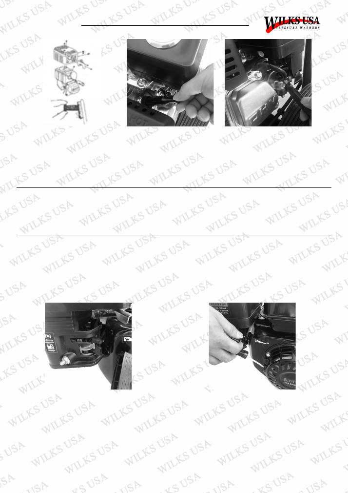
Unscrew two nuts and remove the exhaust elbow from the engine body.
Unscrew five screws from the muffler guard and take it out.
Unscrew from the spark plug eliminator and separate the muffler.
Clean the spark eliminator mesh with a wire brush.
Reinstall the spark plug eliminator in reverse order of removal.
Caution:
Be careful not to damage the spark plug eliminator. Never use a damaged spark eliminator.
Carburettor Idling Adjustment
Start and pre-heat the engine until it reaches normal working temperature. Obtain standard idling by adjusting
the throttle fixing screw under the engine. Standard idling: 3400±300 RPM.
16
© Wilks-USA
TX750 / TX750i
Transport
Transport with the fuel switch in the OFF position. Ensure the engine is cooled so as to avoid the risk of burns
or fire.
Caution:
Do not tilt the engine to avoid spilling fuel. Spilled fuel or vapour will ignite.
Storage
If the engine is not to be used for a long period of time ensure it is stored correctly. Make sure the storage area
is dry and free of dust.
Prepare For Storage
Disconnect the spark plug. Put a spoonful of fresh engine oil into the cylinder and rotate the engine to distribute
the oil evenly. Replace the spark plug. Pull the recoil starter handle until you feel resistance and then keep
pulling so as to align the arrow of the starting sleeve with the hole of the starter: This will close both the inlet
and outlet valves to help prevent rusting inside. Cover the engine to keep it free of dust.
17
© Wilks-USA
TX750 / TX750i
Removal Fom Storage
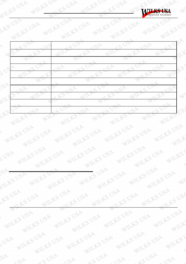
Before re-using, service the engine in accordance with the instructions in the following table. Table for removal
from storage only. For full service schedule, see Page 18.
Storage Time
Service Item
Within One Month
No Service Needed
One - Two Months
Drain out the original fuel from the fuel tank and refuel
Two Months - One Year
Drain out the original fuel from the fuel tank and refuel
Drain out the original fuel in the carburettor
Empty the deposit cup
Above One Year
Drain out the original fuel from the fuel tank and refuel
Drain out the original fuel in the carburettor
Empty the deposit cup
Move the engine from the storage place and start up
1. Unscrew the drain plug and drain out the fuel in the carburettor.
2. Turn off the engine switch first, disconnect the deposit cup and empty it.
Note:
Do not dump oil containers or discard engine oil into the ground. For environmental protection take discarded
engine oil in a closed container to a recycling centre.
Warning:
Fuel is extremely flammable and explosive under certain conditions. Keep cigarettes, naked flames and sparks
away from the operating site.
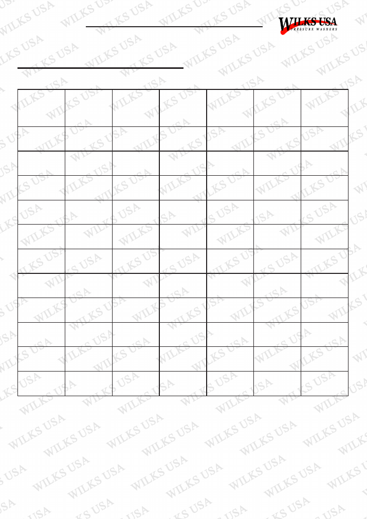
Service Schedule
To keep the engine in sound condition, the user should maintain it according to the table below.
Caution:
Use parts that are supplied by the manufacturer, otherwise damage to the engine may occur..
Warning:
Stop the engine before servicing. If servicing is required with the engine running, ensure there is good
ventilation in the area. Exhaust emissions contain carbon monoxide which may cause injury or be fatal if
inhaled.
Engine Oil Replacement
Place the machine on a level surface and warm up the engine for several minutes. Then stop the engine.
Remove oil filler cap. Place an oil pan under the engine. Remove the oil drain plug so that oil can be completely
drained. You will need to use a tube or other similar device to prevent oil leaking onto the frame of the pressure
washer. Check the oil drain plug, gasket oil filler cap and O-ring - if damaged replace. Reinstall the oil drain
plug. Add the oil to the upper level of the dipstick or lower threads as required.
Note: Do not dump oil containers or allow oil into the environment. Always dispose oil at an appropriate
recycling centre.
18
© Wilks-USA
TX750 / TX750i
Component
/ Task
Every Use
After First 5
Hours Use
First Month
or 20 Hours
Use
Every 3
Months or
50 Hours
Use
Every 6
Months or
100 Hours
Use
Every Year
or 300
Hours Use
Engine Oil
Check
Replace
Replace
Oil Leaks
Check/repair
as necessary
Air Filter
Check
Clean
Clean and
replace as
necessary
Clean and
replace as
necessary
Clean and
replace as
necessary
Clean and
replace as
necessary
Valve
Clearance
Adjust as
necessary
Combustion
Chamber
De-coke as
necessary
Idle Speed
Check/adjust
as necessary
Nuts & Bolts
Check/tighten
as necessary
Check/tighten
as necessary
Check/tighten
as necessary
Check/tighten
as necessary
Check/tighten
as necessary
Check/tighten
as necessary
Fuel Tank
Flush and
clean
Flush and
clean
Flush and
clean
Fuel Line
Check
Check/Clean
Replace as
necessary
Replace as
necessary
Replace as
necessary
Replace as
necessary
Fuel Filter
Check
Check/Clean
Clean and
replace as
necessary
Clean and
replace as
necessary
Clean and
replace as
necessary
Clean and
replace as
necessary
Spark Plugs
Check/Clean
Clean and
replace as
necessary
Clean and
replace as
necessary
Clean and
replace as
necessary
Clean and
replace as
necessary
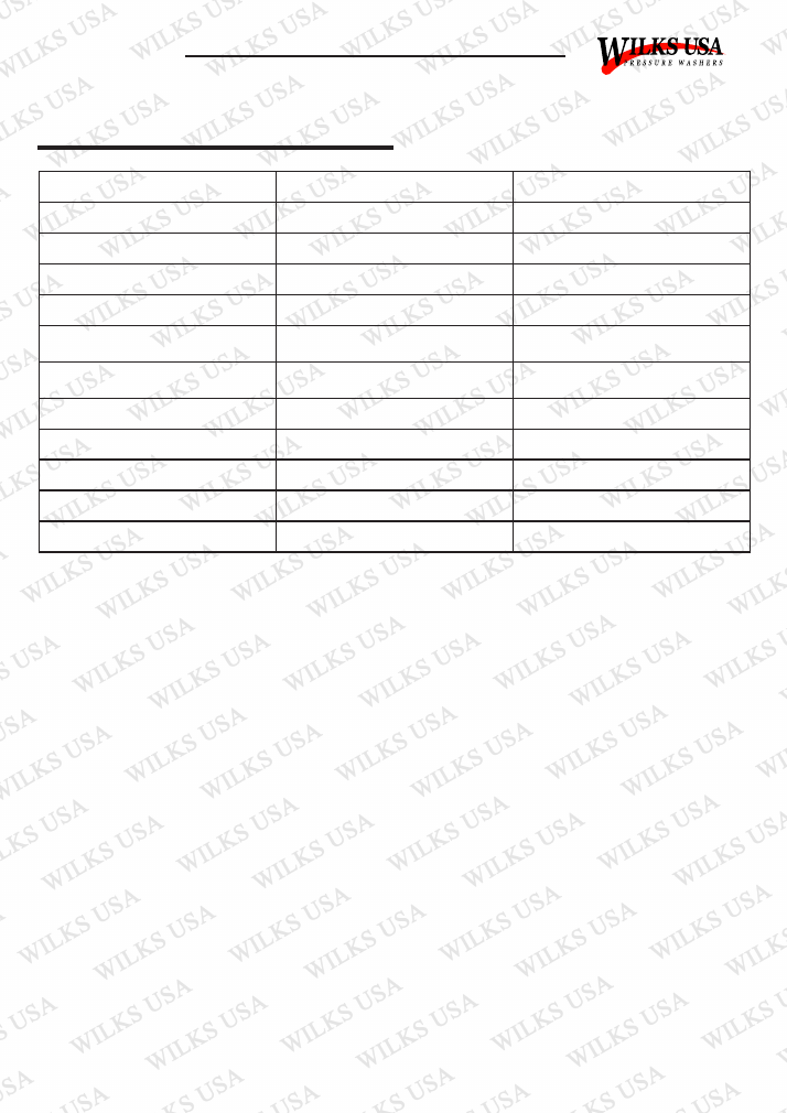
Service and maintenance tasks to be conducted by qualified technicians / authorized repair centres only.
Service Schedule Table
1. For the convenience of transport the Pump is not supplied with oil, and the Breather Plug is not installed
(Certain models only). Please add 15W-30 - 10W-40 Machine oil before using. Pump oil is to be topped up the
centre line of the sight glass, then install the breather plug.
2. After first 20 hours use, remove the pump oil. Add a similar level of kerosene and operate the machine
without load for 10-15 seconds. Shut off the machine, drain of kerosene and replace with new motor oil.
3. Please check the oil mass before using. If lower than the centre line on the spy glass, top up to the centre
line.
4. Accumulative use after 100 hours, change the oil in the same way. For every 100 hours use thereafter, repeat
the oil change/service. It is very important in order to extend the service life of the pump.
19
© Wilks-USA
TX750 / TX750i
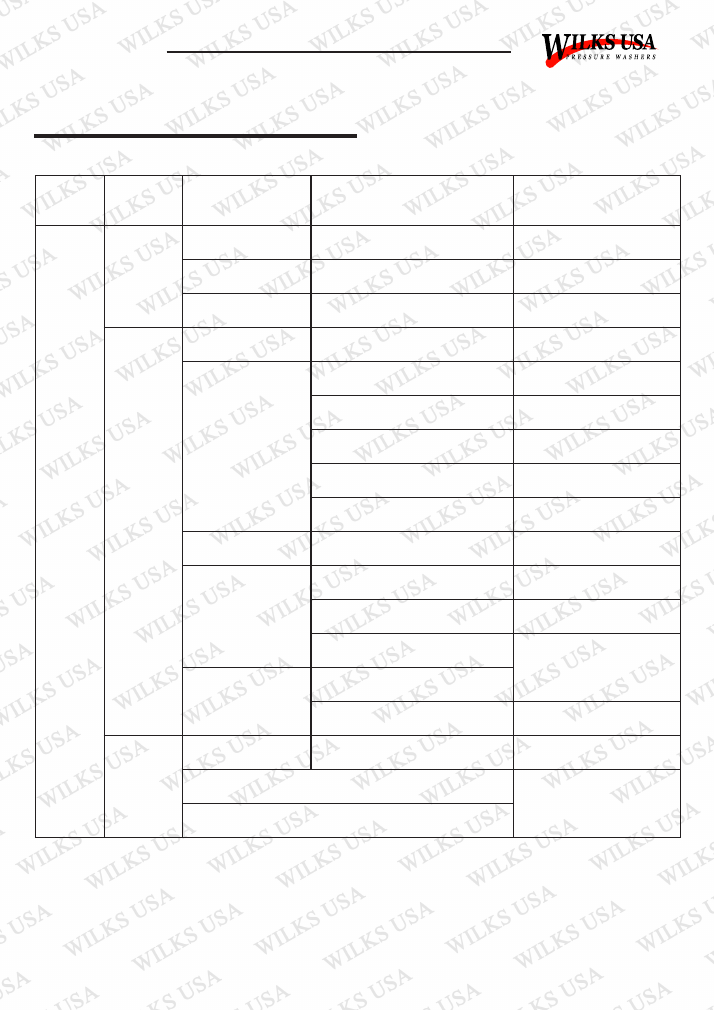
Troubleshooting
Trouble
Probable Cause
Remedy
Fluctuating Pressure
Pump sucking in air
Check connections are tight
Valves dirty, worn or seized
Contact customer helpline
Blocked jet
Remove blockage using jet cleaning tool
Water leakage from pump
Seals worn out
Contact customer helpline
The pump does not reach the required
pressure
Pump sucking in air from connections
or hose
Check tightness of all connections
Suction/delivery valves are clogged
Clear or replace valves. Have machine
checked by Service Centre
Unload valves are stuck
Loosen and re-tighten regulating screw
Lance or nozzle worn out
Check and/or replace
Pump is running but no water delivery
Kinked inlet and or pressure hose
Check, straighten and replace if required
Blocked inlet filter
Remove and clean filter
Blocked jet
Remove blockage using jet cleaning tool
20
© Wilks-USA
TX750 / TX750i
Fault
Probable
Cause
Repair
Engine
won’t start
Low
engine
output
Engine
runs
erratically
Insufficient
compression
Loose spark plug
Tighten plug
Loose cylinder head bolt
Tighten bolt
Damaged gasket
Replace gasket
Sufficient
compression
Fuel System Problems
No fuel supplied to
combustion chamber
Insufficient pulling speed for recoil starter
Pull rope sharply
Foreign matter in fuel tank
Clean tank
Clogged fuel line
Clean fuel line with suppliers
advice
No fuel in tank
Add fuel
Fuel tap not open
Open fuel tap
Fuel System Problems
Combustion chamber
(Poor spark)
Spark plug dirty with carbon or wet with
fuel
Remove carbon or dry spark plug
Damaged spark plug
Replace spark plug
Faulty magneto
Consult dealer
Combustion chamber
(Good spark)
Improper adjustment of carburettor
Insufficient pulling speed for recoil starter
Pull rope sharply
Wrong grade of fuel
used
Check grade of fuel
Overloading
Check working conditions
Overheating
Troubleshooting
21
© Wilks-USA
TX750 / TX750i
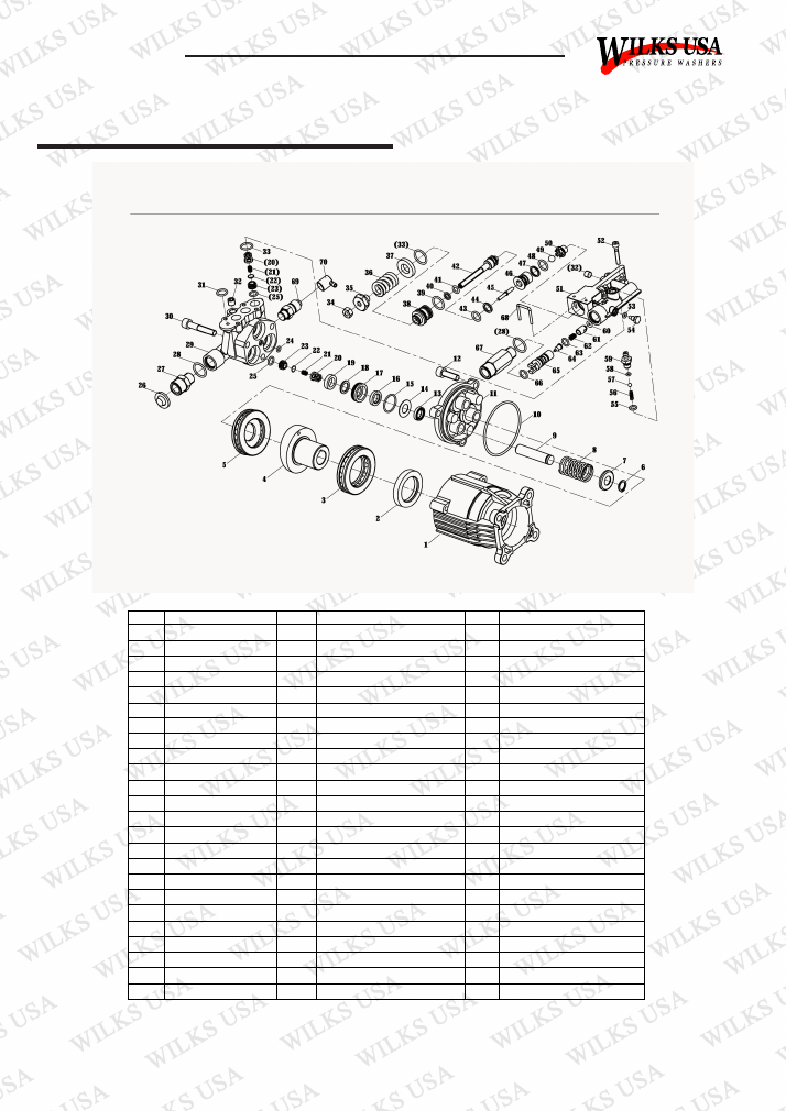
Pump Parts Diagram
Item
Name list
Item
Name list
Item
Name list
1
back housing
25
o-ring 9*1.8
49
φ7/9Cr18 steel ball
2
B35528 oil seal
26
inlet filter
50
lower seat
3
thrust bearing2
27
inlet connector
51
outlet valve body
4
wobble plate
28
o-ring 14*1.8
52
screw M5*30
5
thrust bearing1
29
manifold
53
o-ring 4*2
6
washer 12
30
screw M8*45
54
block 2
7
spring plate
31
o-ring 12*2
55
o-ring 7.65*1.78
8
piston spring
32
throat plug
56
small spring
9
piston
33
o-ring 14*2
57
steel ball φ3/16
10
o-ring 73*2.65
34
nut M6
58
o-ring 3.68*1.78
11
piston seat
35
regulating nut
59
fixed injector
12
screw 8*25
36
regulating pressure spring
60
o-ring 4*2.65
13
oil seal12*20*6
37
washer
61
unilateral valve core
14
washer
38
valve cover
62
unilateral valve spring
15
o-ring 22.4*1.8
39
o-ring 12.42*1.78
63
o-ring 9*1.8
16
seal washer 12*20*4
40
backup ring6.2
64
nozzle
17
packing supt.
41
o-ring 6.07*1.78
65
Venturitube
18
washer
42
valve rod
66
o-ring 10*1.8
19
washer seal 12*20*5
43
o-ring 8.5*1.8
67
outlet connector
20
valve boot
44
PTFE/8.7*11.6*1.25
68
pin
21
valve spring
45
pin
69
thermal relief
22
valve gasket
46
upper seat
70
TRV outlet protector
23
valve seat
47
PTFE/10.3*13*1.25
24
o-ring 4.5*1.8
48
o-ring 10*1.8
22
© Wilks-USA
TX750 / TX750i
CE Declaration of Conformity
EC Declaration of Conformity
with the
European Machinery Directive 2006/42/EC
We hereby certify that the machine detailed below complies with all relevant provisions of the EC
Machinery Directive 2006/42/EC and National Laws and Regulations adopting this Directive.
----------------------------------------
Declaration Ref. No.:-
Manufacturer:-
Manufactures Address:-
Authorised Representative (in EU):-
Authorised Representative’s Address:-
Name of the person authorised to compile the technical
file (in EU):-
Address of the person authorised to compile the
technical file (in EU):-
Product:-
Description:-
Type / Model No.:-
Procedure for assessment of conformity conducted by:-
We hereby declare that the machine detailed also
complies with all relevant provisions of the following
other EC Directives:-
Harmonised Standards Applied (in full):-
TX750 / TX750i
Union Mart Ltd
Unit 4, Mauretania Rd, Nursling Industrial Estate, Nursling,
Southampton SO16 0YS, UK
Union Mart Ltd
Unit 4, Mauretania Rd, Nursling Industrial Estate, Nursling,
Southampton SO16 0YS, UK
Michael S McQuaide
Unit 4, Mauretania Rd, Nursling Industrial Estate, Nursling,
Southampton SO16 0YS, UK
Petrol Pressure Washer Wilks-USA TX750 / TX750i
Petrol High Pressure Washer
Wilks-USA TX750 / TX750i
ISET S.r.l. Sede Legale e Uffici
(Note: Machinery is NOT referred to in Annex IV)
2006/42/EC Machinery Directive
2000/14/EC Noise Emission
2014/30/EU EMC Directive
EN 60335-2-79:2012
EN 1679-1:1998+A1:2011
EN 55012:2007/A1:2009
Person empowered to
draw up the declaration:-
Position:-
Place of issue:-
Michael S McQuaide
Managing Director
Unit 4, Mauretania Rd, Nursling Industrial
Estate, Nursling, Southampton SO16 0YS
Signature: -
Date:-
15.08.2018
----------------------------------------
This declaration relates exclusively to the machinery in the state in which it was placed on the market, and excludes
components which are added and/or operations carried out subsequently by the final user