Full Text Searchable PDF User Manual
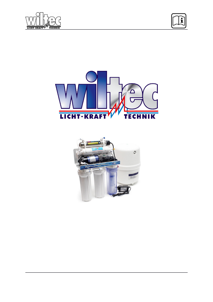
Operation Manual
Reverse Osmosis (RO) System
NW-RO50-C1/C1-1/G1/G1-1/A2UV/A1/NP35/H/E2/D1
NW-RO-BX23
NW-RO-400-E2
Read and follow the operating instructions and safety information before using for the first time.
Technical changes reserved!
Due to further developments, illustrations, functioning steps and technical data can differ
insignificantly.
Updating the documentation
If you have suggestions for improvement or have found any irregularities please contact us.
© by WilTec Wildanger Technik GmbH
Seite 16
Version 3.2016

The information contained in this document is subject to change without prior notice. No part of this
document can be copied or duplicated in another form without
the prior written consent of WilTec
Wildanger Technik GmbH. The WilTec Wildanger Technik GmbH assumes no liability for any errors in
this user manual or the connection diagram.
Although WilTec Wildanger Technik GmbH has made every effort to make sure that this user manual is
complete, accurate and updated, errors cannot always be avoided. In the event of problems with this
user manual please complete and send this form back to us.
FAX-notification (++
+49 2403 55592-15
),
from: ________________________________________
Name:
________________
Firm:
_____________________
Tel/Fax:
__________________
I would like to report the following mistakes:
_______________________________
____________________________________
Customer Service WilTec Wildanger Technik GmbH
e-mail:
Tel:++ +49 2403 55592-0
Introduction
Thank you for purchasing this quality product.
To minimize the risk of injury by means of fire or
electric shock we urge that our clients take some basic safety precautions when using this
device. Please read the operation instructions carefully and make sure you have understood its
content.
Always use a grounded power connection with the appropriate mains voltage. You can find the
corresponding mains voltage on the type plate. If you have any doubts about the connection being
grounded, have it checked by a qualified professional. Never use a faulty electric cable.
Do not inspect the electrical part of the pressure pond filter in a wet or damp environment or when you
are wet yourself and protect it from direct sunlight. Install this device in a safe location so that nobody
can step on the cable, fall over or damage it. Disconnect the power plug before cleaning it and use
only a damp cloth for cleaning. Avoid using cleaning agents and make sure that no liquid enters the
electrical part of the pump.
The electric part of the device contains no parts that can be inspected or serviced by the user. Leave
the maintenance, adjustment and repair to qualified technical personnel. In case of unauthorised
intervention the 2-year warranty is no longer valid! Keep these operation instructions safe.
© by WilTec Wildanger Technik GmbH
Seite 17
Version 3.2016
Collection Instructions
This Manual describes the Usage of all our RO.Systems.
Please note that some parts of this manual are intended for certain systems.
Usually the arrangement of the filter stages is always the same. The number of filter stages are de-
pending on the model you bought, between 1 and 6.
For RO-Systems without pump:
If you use pressure tank, input water pressure should be higher than 85 psi.
Operation Principle
The RO system adopts U.S. high-tech reverse osmosis technology. This automatic reverse osmosis
system is composed of five filtration stages
.
First, The raw water is filtered by three pre positive car-
tridges
.
The
first stage
:
PPF cartridge, remove suspended substance and other substances up to 5 micron in
raw water. The
second stage
:
granular activated carbon cartridge;
the
third stage
:
high density activated carbon cartridge, to remove odor
、
chlorine and its outgrowth in
raw water
.
After above three stages of filtration, the filtered water is pushed into the
fourth stage
: the reverse os-
mosis (RO) membrane with a high-pressure pump. Since the aperture of the RO membrane is only
0.0001micron, bacteria and filterable virus can pass the RO membrane only if the bacteria would be
reduced in size 4000 times, and filterable virus would be reduced in size more than 200 times. Conse-
quently, any super fine impurities, harmful soluble solid, bacteria and virus in water is blocked by the
high density RO membrane
.
The RO membrane can also filter other impurities and contamination from the filtered water. The harm-
ful substance is automatically removed by means of a waste water outlet. The water filtered through
the RO membrane enters a pressure tank for storage
.
When the user turns on the goose-neck faucet,
the purified water will go through the
fifth stage:
post positive bacteriostatic activated carbon filtration
and into the
Sixth stage:
UV light to kill bacteria, virus and son on or mineral balls to put minerals
back into the water again.
The system controls the water purification process automatically. When the pressure of raw water is to
low or the water storage tank is full, the system will stop the purification machine automatically; When
the water pressure
the normal level, the purification machine will turn on automatically.
The water purified by the RO system is pure drinking water without bacteria and impurities, rich in oxy-
gen, tasty and excellent for your health.
The different filter stages:
Filter
Materials
Functions
Material life
in average
1
st
Stage
PP 5 micron
Un-dissolved contaminants removal, i.e.
sand, silt, rust, etc.
About 10 months
2
nd
Stage
Activated carbon
Activated carbon germicidal adhesion re-
moval of chlorine, organic fertilizer, agricul-
tural chemical, insecticide
About 10 months
3
rd
Stage
Block carbon
Same as 2nd stage, but re-filtration again
About 10 months
4
th
Stage
RO membrane
Heavy metal removal: particles, heavy
metal, ray, bacteria. etc.
About 2 years
5
th
Stage
In-line carbon
Adhere odor & taste and make water deli-
cious
About 1 year
6th Stage
UV-Light
Kills virus and bacteria
About 1 year
6th Stage
Mineral Ball
Puts minerals into the water
About 10 month
© by WilTec Wildanger Technik GmbH
Seite 18
Version 3.2016
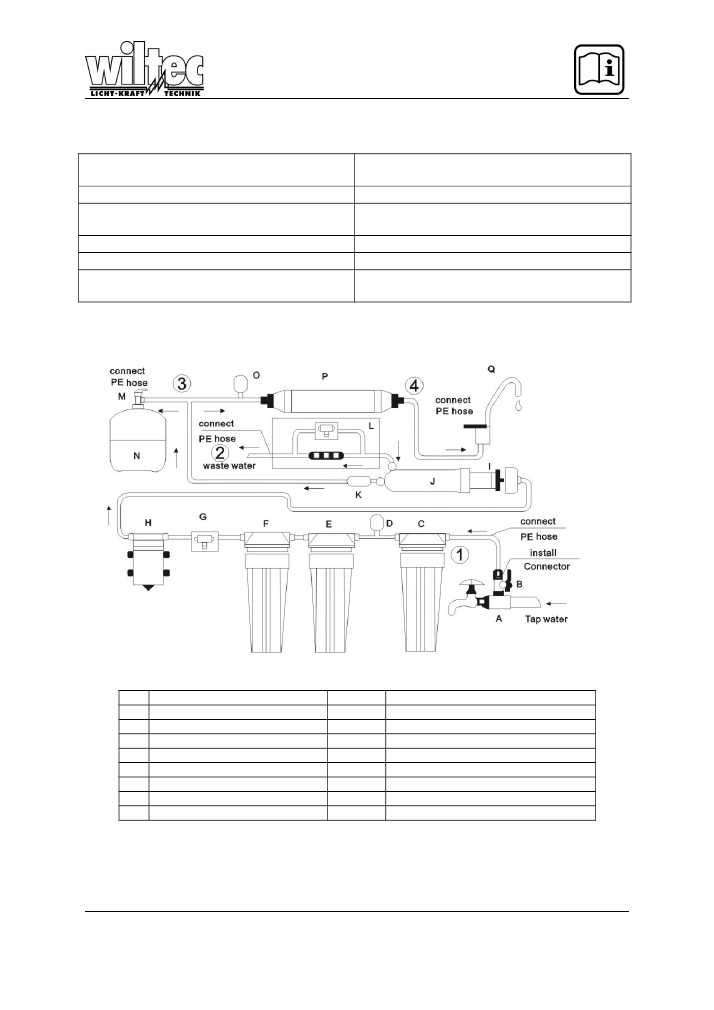
Technical Process
Tap Water
PPF Filter
RO-System
-
Waste water outlet
Low pressure switch
High pressure switch
Granular activated carbon
Postpositive bacteriostatic activated
carbon
High density activated carbon
Sixth filter stage
Booster pump
Purified water
4 way valve
Flow out from goose neck faucet
-
Pressure tank
RO-System und Aufbau
A
3-Way feed water connector
B
Ball valve
C
PP Sediment Cartridge
D
Low pressure switch
E
Activated carbon
F
Activated carbon block
G
Flow in valve
H
Booster pump
I
RO-Membrane
J
Membrane housing
K
Check valve
L
Drain restrictor & Flush valve
M
Tank valve
N
Pressure tank
O
High pressure switch
P
Gourmet filter
Q
Goose Neck faucet
1;2;3;4
Connect plastic hose
© by WilTec Wildanger Technik GmbH
Seite 19
Version 3.2016
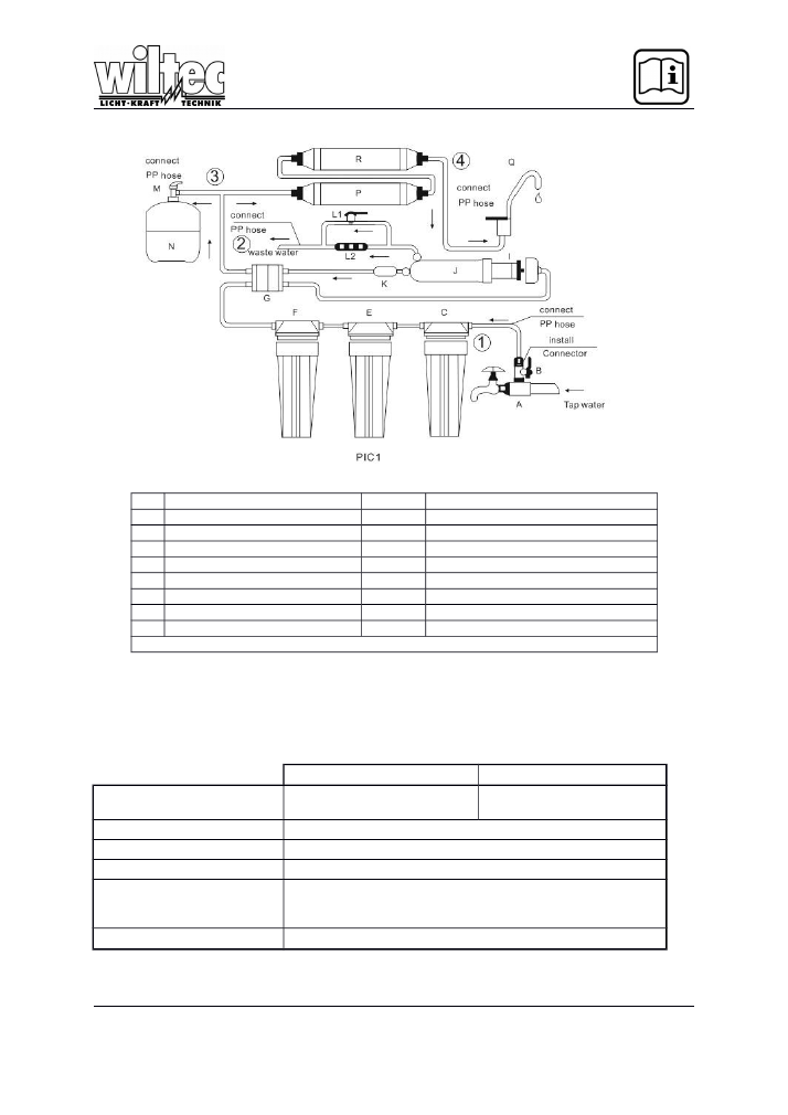
A
3-Way feed water connector
B
Ball valve
C
PP Sediment Cartridge
E
Activated carbon
F
Activated carbon block
G
Flow in valve
Booster Pump*
I
RO-Membrane
J
Membrane housing
K
Check valve
L1+L2
Drain restrictor & Flush valve
M
Tank valve
N
Pressure tank
O
High pressure switch
P
Gourmet filter
Q
Goose Neck faucet
R
Mineral Ball / UV Light
1,2,3,4 connect plastic hose
In PIC1 the booster pump is missing. Usually it is between the third filter stage and the RO-Membrane,
like it is in the technical drawing on the page before.
Please note that availability of a sixth filter stage is depending on the type of system.
Technical Data
RO-50-XX / RO-BX-XX
RO-400-XX
Purified Water Output
50GPD / 185 l/day (25°C)
400 GPD / 1500 l/day
(25°C)
Tank Capacity
3 Gallons
Inlet Water temperature
4-42°C
Applying Water Pressure
1 – 3,5 bar 0,1 – 0,35 MPa
Clean Water Content rela-
tive to inlet Water
15-20%
Water Supply
Tap Water or Ground water TDS 1000ppm less
© by WilTec Wildanger Technik GmbH
Seite 20
Version 3.2016
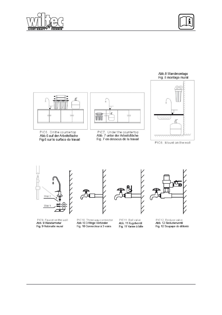
Installation
The system installation method should be determined in accordance with the layout
of your kitchen. Please refer to the installation maps as follows. If the RO unit would
be suspended on the wall
,
it should be fixed with two M6 swelling screws or two con-
crete steel nails according to the aperture on the RO unit hanger plate
© by WilTec Wildanger Technik GmbH
Seite 21
Version 3.2016
1. To install the ball valve, fit a three way feed water connector (A) and place the ball valve(B) on the
three way feed water connector(A), then connect the tap water faucet with three way feed water
connector ( Pic 1,7 and 8).
2. To install the RO membrane
:
screw off the cap of RO housing (J)
,
put the one end with two sealing
rings of RO membrane (I) first into the RO housing
,
screw on the cap tight.
3. The goose-neck faucet (Q) should be positioned for good aesthetics, function and convenience; it
connects to the outlet fitting of the mineral ball filter by means of the white plastic hose.
4. To install the plastic hose at following positions according to technological process. There are
marks numbered 1, 2, 3, 4, on the
Reverse osmosis system layout and components
chart
( Pic1).
You can also find these marks on the RO machine.
Mark 1:
Between water tap and PPF filter(C) with white plastic hose.
Mark 2:
Installing a drain tubing white plastic hose linking to the off let of drain restrictor and
flush valve. Put the drain tubing to sewer or connect with a container for usual washing
.
Mark 3:
Between the valve outlet(M) on water storage tank(N) and the Tee in front of post bac-
teriostatic activated carbon filter(P) with white plastic hose.
Mark 4:
Between the goose-neck faucet (Q) and the post bacteriostatic activated carbon filter
or mineral ball filter if available.
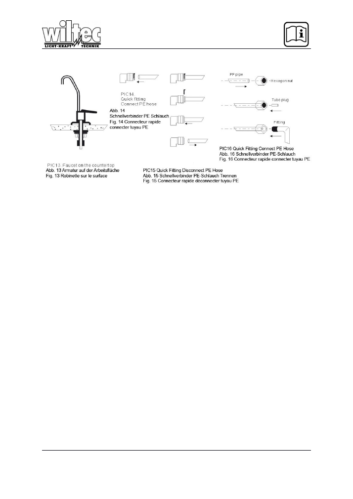
5. Method of connecting plastic hose with fittings
Cut a plastic hose after measuring.
Place the plastic hose into hexagon nut. ( Pic12)
Place white tube plug into the nozzle of plastic hose push the tube plug to the plastic hose end
by hand or tools. ( Pic12)
Place the plastic hose into the fittings. (Pic12)
Screw on the hexagon nut tightly.
5.1. Method of connecting plastic hose with quick fittings (PIC10)
Cut a plastic hose after measuring.
Insert plastic hose deep into the quick fitting
5.2. Method of disconnecting the plastic hose from the quick fittings (PIC11)
Remove the small part
Press the round part until it touches the main body of quick fitting.
Pull the plastic hose.
6.
Power cord.
This system is equipped with a transformer which uses single-phase power supply of 220V (See
transformer voltage). To use it, please plug the power cord of transformer into power supply
socket.
© by WilTec Wildanger Technik GmbH
Seite 22
Version 3.2016
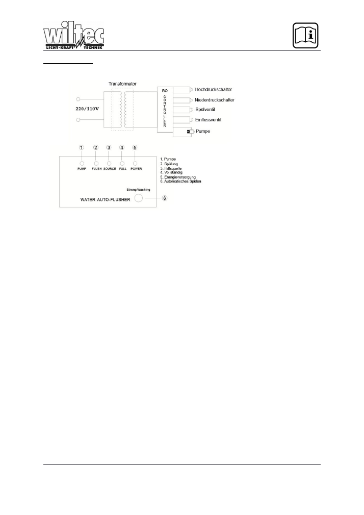
Funktionsprinzip
Once the system is turned on, it flushes 30 seconds, will.
• After two hours of cleaning the water, it flushes again for 30 seconds.
• After five seconds, the system responds to the low pressure switch
• If the high pressure switch operates, the system stops after 20 seconds.
• If the key (6) "Strong Washing" is pressed, the system purges for 20 seconds.
• Are the LEDs (1), (3), (5) is switched on, is hereby indicated that the system produces pure water.
• Are the LEDs (3, (4), (5) is switched on, is hereby indicated that the pressure tank is full.
• If the LEDs (2, (3), (5) is switched on, is hereby shown that the system is flushed.
© by WilTec Wildanger Technik GmbH
Seite 23
Version 3.2016
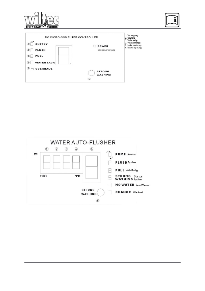
• If the system is turned on, it flushes for 30 seconds, the display (display) is analogous (2).
• After rinsing, pure water is produced, the display is analogous (1).
• When the pressure tank is full, the system comes to a standstill, the display is analog (3).
• A warning buzzer will be shown unless a lack of feed water is or the pressure of the incoming water is too
low, the display is analogous (4).
• After two hours of production of pure water, there is again a 30 second rinse.
• In the event that the system is working for an unusually long timeframe, it is automatically switched off,
which likewise warning buzzer is activated, the display is analogous (5).
• If you press the button (6) for strong flushing (Strong Washing) is rinsed for 30 seconds.
RO Kontrollbox
1. st digit diode (1): Two viewing options "E" control beeps "P" Control is silent
The function can be changed by pressing for 2 seconds the "STRONG WASHING" key (6).
2. Paragraph diode (2) (3) (4) show the TDS value. If the system flushes, the digit diodes (3) (4)
show the remaining seconds for rinsing
3. Paragraph diode (5) shows the operating state of the system. The explanation can be found
on the right side of the controller.
4. Press the button (6) to flush the system
© by WilTec Wildanger Technik GmbH
Seite 24
Version 3.2016
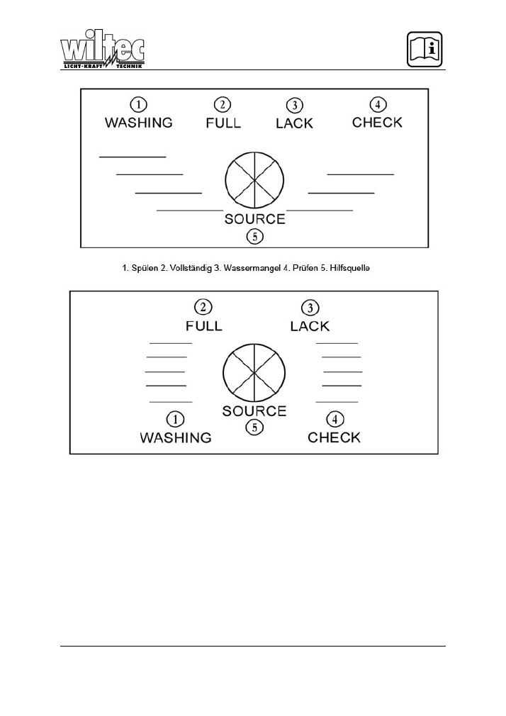
-
If the system is turned on, is rinsed for 30 seconds, the display is analogous diode (1).
-
After flushing the system begins with the production of pure water, the display is ana-log
diode (5)
-
After the pressure tank is full, the system comes to a standstill, the display is analogous
diode (2)
-
Using buzzer indicates whether a lack of feed water is present or whether the to-run water
pressure is too low, the display is analogous diode (3).
-
After two hours the preparation of pure water, is rinsed for 30 seconds, the display is anal-
ogous diode (1).
-
Where has worked the system for an unusually long period, it is automatically-table to stop
at the same time warning buzz, the display is analogous diode (4).
© by WilTec Wildanger Technik GmbH
Seite 25
Version 3.2016

Operational Approach
After the installation
,
please wash the filters of each stage before using the system for the first time.
The steps is as follows:turn on the ball valve( B) of the faucet tubing, turn off the tank valve(M) of wa-
ter storage tank(N),turn on the goose-neck faucet(Q),
Open the flush valve (L1)).
plug the power cord into power supply socket
,
then the high pressure pump(H) starts up automatically
,
the waste water outlet begins to drain
,
filters
of each stage are being washed automatically.
After washing the tank, turn on the tank valve (M) of water storage tank (N) and turn off the goose-
neck faucet (Q), the reverse osmosis filter begins to generate purified water. When you use this sys-
tem for the first time, let the purified water flow out from the full water storage tank twice, then the puri-
fied water is suitable for drinking.
Notes:
A) When you use the system for the first time, turn on the goose-neck faucet to drain the
water. (There could be a little bit of black water flowing out from faucet
,
please continue
washing to drain it)
B) When you use the system for the first time, TDS test data may be a bit high
,
please con-
tinue washing until the TDS test data becomes normal.
C) When you use the system for the first time, the purified water is not drinkable until steps
A and B are done. The concentrated waste water used for the making of the purified wa-
ter cannot be used for drinking.
After the installation & adjustment, the system begin to produce purified water automatically
.
Usually,
turn off the goose-neck faucet(Q)
、
turn on the tank valve(M) of water storage tank
,
let the purified water
flow into tank. When the water storage tank is full of purified water
,
the system stops working automati-
cally. Turn on the goose-neck faucet (Q) to use the purified water.
Maintenance
It is highly recommended to replace filters periodically to keep the high quality of water. This helps to
take full advantage of filters and guarantee the standard of water quality. If a user takes care of the fil-
ters and replaces them periodically, the water purifier system could have a longer lifetime. The period
of Filter-replacement depends on the quality of the raw water, the impurity quantity of the raw water.
Based on empirical statistics a family of four persons usually consumes l0L (10kgs) purified water
each day.
© by WilTec Wildanger Technik GmbH
Seite 26
Version 3.2016

RO membrane pressure washing
:
When RO membrane purifies the water, there is impurity and bacteria left on the surface of the water,
which may affect the quality and volume of the purified water
.
Thus the RO membrane must be
cleaned periodically
.
In our system, the RO system will flush the RO membrane manually by turning on
the flush valve (L1) for 2-3 minutes once a week.
Notice
:
In order to make you system work efficiently, please use the specified filters, provided by the
same vendor of the purification system.
Warning
1)
Don't drink the water of first two tanks; let it drain or use it for other utilities upon installation. And
test the RO unit for about 2 hours until the above operations is completed successfully.
Clean the remaining contaminants and sediment in the unit.
Check if the unit works normally and without water leakage.
2)
Don’t take apart the parts of system. Any wrong operation may lead to water leakage and system
failure/damage.
3)
Don't apply the system to purify hot water.
4)
Don’t place air valve discharged on the pressure tank.
5)
To ensure the quality of purified water, please replace the first and the second filters in a period of
no longer than 10 months.
6)
Please check the power supply and make sure it is a suitable voltage.
7)
Keep the RO unit away from sunshine.
8)
When the system is not used for a long period, please turn off the power and shut off the ball
valve.
9)
Follow the initial operation before reusing the system after longtime standing idle.
Load move and install it carefully.
© by WilTec Wildanger Technik GmbH
Seite 27
Version 3.2016

Trouble Shooting
If the following problems occur, please check as follows:
1)
Pump can not work to generate purified water
:
Check if the pressure of water supply is high enough to work. The RO controller box
does not start the pump under low pressure.
Check if either high pressure switch or flush valve works, (stuck)
Check if the fuse on transformer is burned
,
if so, then check if post in-line carbon
filter(T33) or PP cartridges is blocked, it may cause the pump to be overloaded
2)
RO system does not operate.
Check if power supply is normal.
Check if the feed water ball valve has been turned on (check if water pressure is nor-
mal).
Check if the water storage tank is full of water
3)
RO system can not operate automatically
Check if there is any wrong operation.
Check if the high and low pressure valve is normal.
4)
Pump head leakage:
Check if post in-line carbon filter (T33) or PP cartridges are blocked this may cause the
leaking. Sometime the leakage may be caused by the increased pressure of the water
in the pump head that cannot be released outward. If so, replace all the carbon car-
tridges and send the pump for repair.
Also either a weakened diaphragm or the blocked scale could cause the leaking.
The water can not flow out due to the blocked RO membrane, which is caused by a
blocked flow restrictor. This cause the pump head to be filled with high pressure water
that can cause a leak. It could be rectified by improving the relevant components.
Pump is operating normally
,
but can not generate purified water:
The cause may be that the RO membrane is blocked or pump is out of pressure. If the
RO membrane is blocked
,
please replace the RO membrane. If the cause is that the
pump has no pressure
,
please check if it is due to either the pump being loaded for to
long a time or the filtering materials is often blocked and the adequate maintenance is
not done
,
this can caused the pump structure to be weakened. Send pump for repairing.
5)
No purified water coming out while tank is full of water
:
The cause may be the air inside the tank is out. Please recharge the air (7 psi) and
check if the tank has air leakage. If it does, please replace the tank.
If the post in-line carbon filter is blocked. Please replace the filter.
6)
The wastewater keeps on discharging when the tap of RO system is closed.
Check if flush valve is operating normally; otherwise, replace it.
The input water valve was damaged.
7)
RO system could not be completely stopped or restart operating quickly while the tank is full.
High-pressure switch is out of work. Please repair or replace it.
Check if valve is releasing pressure and is not stuck. Please replace it.
8)
The volume of purified water is too little
:
Check if the filters are not to dirty and exceeded the filter's service life
.
If it is caused by
the RO membrane that is to dirty or not be flushed regularly. Please replace it.
Check if temperature of water is to cold.
The water delivering pressure is not as good as that of the new system. Please replace the pump
© by WilTec Wildanger Technik GmbH
Seite 28
Version 3.2016
Disposal regulations
EU guidelines regarding the disposal of scrap electric appliances (WEEE, 2002/96/EC) were
implemented in the law related to electrical and electronic equipment and appliances.
All WilTec electric devices that fall under the WEEE regulations are labelled with the crossed-out
wheeled waste bin logo. This logo indicates that this electric equipment must not be disposed with the
domestic waste.
The company WilTec Technik GmbH has been registrated in the German registry EAR under the
WEEE-registration number DE45283704.
Disposal of used electrical and electronic appliances
(intended for use in the countries of the European
Union and other European countries with a separate
collection system for these appliances).
The logo on the article or on its packaging points out
that this article must not be treated as normal
household waste but must be disposed to a recycling
collection point for electronic and electrical waste
equipment. By contributing to the correct disposal of
this article you protect the environment and the health
of your fellow men. Environment and health are
threatened by inappropriate disposal.
Materials’ recycling helps reduce the consumption of raw materials.
Additional information on recycling this article can be provided by your local community, municipal
waste disposal facilities or the store where you purchased the article.
Address:
WilTec Wildanger Technik GmbH
Königsbenden 12 / 28
D-52249 Eschweiler
Important notice:
The reprint or reproduction, even of excerpts, and any commercial use, even in part of this instructions
manual require the written permission of WilTec Wildanger Technik GmbH.
© by WilTec Wildanger Technik GmbH
Seite 29
Version 3.2016