Full Text Searchable PDF User Manual
Electrically Released Brake
ERS VAR10 SZ 2500
Service & Installation Instructions
P-2107-WE-A4
SM477GB

WARNER ELECTRIC EUROPE - Rue Champfleur, B.P. 20095, F - 49182 St Barthélemy d’Anjou Cedex
SM477gb - rev 04/16
2/15
CONTENTS
1-
EU DECLARATION OF CONFORMITY ____________________________________ 3
2-
PRECAUTIONS AND SAFETY MEASURES _________________________________ 3
2.1
- S
YMBOLS USED IN THIS MANUAL
_____________________________________________________________ 3
2.2
- S
AFETY PRECAUTIONS FOR INSTALLATION AND MAINTENANCE
_________________________________________ 4
2.3
- P
RECAUTIONS FOR HANDLING
_______________________________________________________________ 5
2.4
- P
RECAUTIONS ON USE
____________________________________________________________________ 5
2.5
- R
ESTRICTIONS ON USE
____________________________________________________________________ 6
3-
STORAGE __________________________________________________________ 6
4-
TECHNICAL SPECIFICATION ___________________________________________ 7
4.1
- B
RAKE DESCRIPTION
______________________________________________________________________ 7
4.2
- T
ECHNICAL DATA
________________________________________________________________________ 7
4.3
- L
ABELING DETAILS
_______________________________________________________________________ 8
5-
INSTALLATION ______________________________________________________ 9
5.1
- C
USTOMER
I
NTERFACE
S
PECIFICATION
_________________________________________________________ 9
5.2
- B
RAKE
M
OUNTING
______________________________________________________________________ 9
6-
ELECTRICAL CONNECTION ___________________________________________ 10
6.1
- M
ICROSWITCH
T
ECHNICAL
D
ATA
____________________________________________________________ 10
7-
MAINTENANCE ____________________________________________________ 11
7.1
- A
IR
G
AP
C
HECKING
_____________________________________________________________________ 11
7.2
- D
ISCS EXCHANGE
_______________________________________________________________________ 12
7.3
- D
ETECTION
C
HECKING
___________________________________________________________________ 12
7.4
- D
ETECTION SETTING
_____________________________________________________________________ 13
7.5
- M
ICROSWITCH EXCHANGE
________________________________________________________________ 13
8-
SPARE PARTS ______________________________________________________ 14
9-
TOOLING _________________________________________________________ 14
10-
TROUBLESHOOTING ________________________________________________ 15
11-
CONTACT _________________________________________________________ 15
WARNER ELECTRIC EUROPE - Rue Champfleur, B.P. 20095, F - 49182 St Barthélemy d’Anjou Cedex
SM477gb - rev 04/16
3/15
1-
EU Declaration of conformity
The Product described in this manual is in conformity with the relevant EU harmonized legislation:
Directive 2014/33/EU
Ensuring lift safety
Directive 2014/35/EU
Electrical safety: Low-voltage electrical equipment
Directive 2006/42/EC
Machinery safety
Evidence of conformity to the Directives is assured through the application of the following standards:
EN 81-1+A3:2009
Safety rules for the construction and installation of lifts – Part 1: Electric lifts (end of the
period of applicability: 31 August 2017).
EN 81-20:2014
Safety rules for the construction and installation of lifts – Lifts for the transport of
persons and goods – Parts 20: Passenger and goods passenger lifts.
EN 81-50:2014
Safety rules for the construction and installation of lifts – Examinations and tests – Parts
50: Design rules, calculations, examination and tests of lift components.
DIN VDE 0580:2011
Electromagnetic devices and components, General requirements.
EN ISO 12100:2010
Safety of machinery – General principles for design – Risk assessment and risk reduction.
2-
Precautions And Safety Measures
Precautions and safety measures must be read before any installation or maintenance of the brake.
Compliance with the instructions and values given by the documentation and marking of the unit is
imperative in order to ensure a proper functioning of the brake.
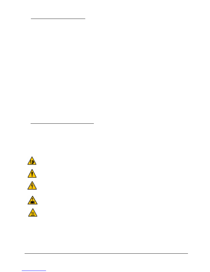
2.1 -
Symbols used in this manual
Action that might damage the brake.
Action that might be dangerous to human safety.
Electrical action that might be dangerous to human safety.
Handling of loads that might be dangerous to human safety.
Surface temperature that might be dangerous to human safety.
WARNER ELECTRIC EUROPE - Rue Champfleur, B.P. 20095, F - 49182 St Barthélemy d’Anjou Cedex
SM477gb - rev 04/16
4/15
2.2 -
Safety precautions for installation and maintenance
During maintenance, make sure that the driving mechanism is stopped and that there is no risk of
accidental starting. The intervention must be signaled and the work area delimited.
All intervention must be done by authorized and qualified personnel, having read and understood
this manual, using adapted procedures and professional tools. All intervention must be done
according the regulation of the country of the installation.
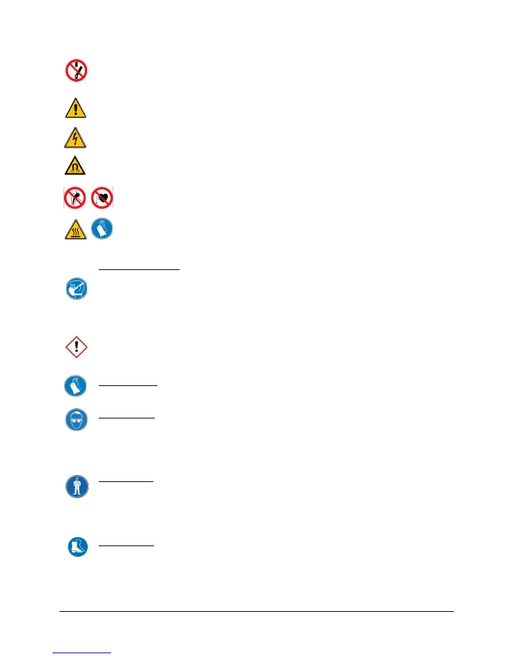
All works on the electrical connections must be done with power off.
Magnetic field generated by the magnet, can create dysfunctions on near machine or device. Users
must also be careful about attractions of tools or other devices during interventions.
Due to the magnetic field generated by the magnet, the bearers of a heart pace-maker or an
implant must avoid the proximity of the unit.
During operation the brake surface can reach temperatures higher than 80°C. Users must be
careful during contact with the unit.
Respiratory protection
Inhalation of large amounts of dust can cause coughs and difficulty in breathing.
Respirator must be worn if exposed to friction material dust. [Dust mask FFP2].
Move to fresh air in case of accidental inhalation of dusts.
In the event of persistent symptoms receive medical treatment.
In case of ingestion of friction material dust, consult a doctor.
Provide appropriate exhaust ventilation at places where friction material dust can be generated.
Do not use brushes, pressurized air or hazardous agents to clean the brake. The use of a vacuum
cleaner is recommended.
Hand protection
Protective and dust-resistant gloves.
Eyes protection
Friction material dust particles, like other inert materials, may be mechanically irritating the eyes.
Safety goggles with side protection.
In case of contact with eyes, carefully rinse with plenty of water.
In the event of persistent symptoms seek medical treatment.
Skin protection
Prolonged skin contact may cause mechanical irritation.
Dust resistant protective clothing.
In case of contact with skin, wash with soap and water as a precaution.
Consult a doctor if skin irritation persists.
Feet protection
Safety shoes must be worn.
WARNER ELECTRIC EUROPE - Rue Champfleur, B.P. 20095, F - 49182 St Barthélemy d’Anjou Cedex
SM477gb - rev 04/16
5/15
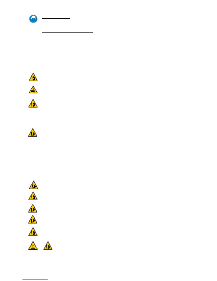
Helmet protection
Safety helmet must be worn.
Protective and hygiene measures
Do not breathe friction material dust.
Wash hands before breaks and at the end of workday.
During maintenance, do not eat, drink or smoke.
Handle in accordance with the general hygienic rules.
Remove and wash contaminated clothes before re-use.
2.3 -
Precautions for handling
Avoid any impact or damage to the brake during handling.
To avoid risk of injury (see mass of the units in the service manual of the brake), use an adapted
device, hoist or crane, for the handling of the unit.
When handling, use the handling holes intended for this purpose.
Never lift the brake using the coil cables.
2.4 -
Precautions on use
Customer is responsible of brake qualification with his interface in order to guaranty that brake
performances are not reduced.
The use of the 2 circuits in redundancy is mandatory.
This brake is designed to work in clean conditions. Friction faces must be kept completely clean of
any oil, water, grease or abrasive dust.
The friction flange, on customer side, must be, also, carefully cleaned and degreased.
The friction faces must be protected, with adapted devices (cover, heating devices, etc…):
•
To avoid pollution and rusting during the lifetime of the unit.
•
To avoid condensation, resulting in freezing conditions, in low temperature/high humidity, or
sticking of the disc.
This brake is designed to work in ambient temperature between 0°C and 40°C.
This brake is designed to work with duty cycle of 50% (Insulation class: 155°C). The temperature of
customer friction flange must not exceed 90°C.
This brake can only be used on « horizontal » position.
When switching on DC-side the coil must be protected against voltage peaks, according
DIN VDE0580.
Make sure the rated supply voltage is set within the tolerances, an under-voltage supply, generates a
reduction of the maximum air gap.
An over-voltage supply generates additional heat on the surface of the brake, with risks
of injury by burning and possible damage to the coil.
WARNER ELECTRIC EUROPE - Rue Champfleur, B.P. 20095, F - 49182 St Barthélemy d’Anjou Cedex
SM477gb - rev 04/16
6/15
Emergency braking
: for emergency braking the switching OFF must be connected on DC current side,
in order to obtain short engaging time of the brake.
Service braking:
for service braking, the switching OFF and ON must be connected on AC current
side, in order to obtain silent switching.
2.5 -
Restrictions on use
Any modification made to the brake without the express authorisation of a representative of Warner
Electric, as far as, any use out of the contractual specification accepted by "Warner Electric", will
result in the warranty being invalidated and Warner Electric will no longer be liable in any way with
regard to conformity.
If maximum rotation speed is exceeded, the guarantee is no longer valid.
The brake must be replaced it is submitted to water projections.
For the brake to comply with directive 2014/33/EU, the installer must observe the general conditions
for installations and use as defined in the EU type certificate, drawn up by the TÜV SÜD Industrie
Service (see EU-BD number in table 1), including the mandatory use of a speed limiting device, in
compliance with EN 81-20 paragraphs 5.6.2.2.1 and 5.6.6.10. Under no circumstances, this device
can replace the system case against the car overspeed in the descending phase.
The customer must be careful to not alter the factory set parameters: Microswitch adjustment.
This brake must not be dismantled.
This brake is designed for static applications. Dynamic brakings are restricted to emergency braking
and test braking.
Unless otherwise specified in the manual service, this range of product is not designed to be used
according 2014/34/EU directive “Equipment for explosive atmospheres” (ATEX).
3-
Storage
These devices are delivered in a package guaranteeing the preservation of the product providing it
is by surface transportation.
In case of a specific request (air or sea transport, long-term storage, etc) contact our factory.
WARNER ELECTRIC EUROPE - Rue Champfleur, B.P. 20095, F - 49182 St Barthélemy d’Anjou Cedex
SM477gb - rev 04/16
7/15
4-
Technical Specification
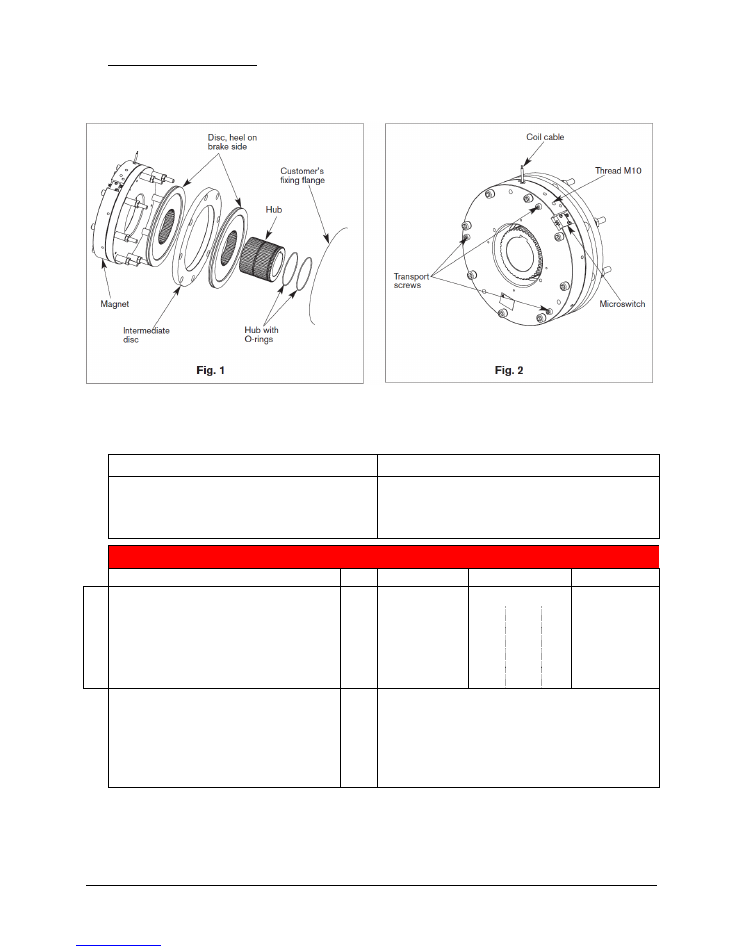
4.1 -
Brake description
4.2 -
Technical data
Table 1
ERS VAR10 SZ2500/----
Certificate :
Directive 2014/33/EU - Norm EN81-20&50 *
EU-BD 592
Directive 95/16/EC - Norm EN81-1+A3**
ABV 592/3 - ESV 592/3
CAUTION: Use a power supply with overexcitation
Size
2500/2200
2500/2500
2500/3000
Pe
r m
ag
ne
t
Torque installed
Nm
2200
2500
3000
Overexcitation voltage
Vdc
207
207 103,5 48
207
Holding voltage
Vdc
103,5
103,5 52
24
103,5
Overexcitation power
Watt
315
315 232 273
315
Holding power
Watt
79
79
59
68
79
Maximum speed
min-1
250
Minimum Air gap
mm
0,4
Maximum Air gap (after wear)
mm
0,7
Cyclic duration factor
ED
60%
Weight
Kg
60
* Brakes produced from 20 April 2016
** Brakes produced until 19 April 2016
WARNER ELECTRIC EUROPE - Rue Champfleur, B.P. 20095, F - 49182 St Barthélemy d’Anjou Cedex
SM477gb - rev 04/16
8/15
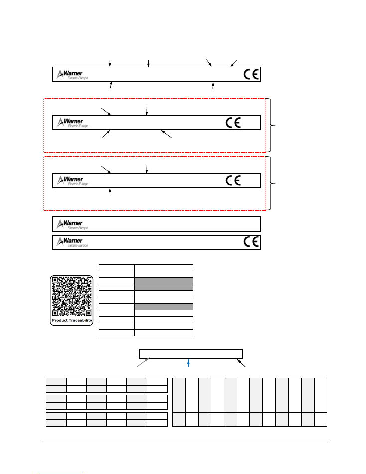
4.3 -
Labeling details
Example of brake labels
In case of presence of QR code label, here is the information contained.
Encoded date details:
Y
M
Day
Example: YN16 is, 2010, 16th February
315/79W
777888-1
CM8
AFAQ
ABVxxx TUV0036 ESVxxx
0333
AFAQ
EU-BD xxx TUV0036
0333
777888-1
CM8
ERS VAR09 SZ1700/1700
Valid until 19th
april 2016
Valid from 20th
april 2016
FRICTION DISC
303xxxxx
7, Rue de Champfleur Z.I.
F-49124 St Barthélémy d'Anjou
207/103Vdc
303xxxxx
ERS VAR09 SZ1700/1700
Voltage
Power
Product N°
Serial N°
WEE Reference
Production date
Type of the brake
Nominal torque / Real torque
Certification CE following 95/16/EC
(TÜV SUD Industrie Service)
Certification EN81-1+A3 (UCMP)
(TÜV SUD Industrie Service)
Type of the brake
Nominal torque / Real torque
EU type-examination certificate 2014/33/EU
(TÜV SUD Industrie Service)
Identify
Data Field
1
Product name
2
Release (NA)
3
Revision (NA)
4
Identification number
5
Serial number
6
Batch number (NA)
7
Manufacturer name
8
Manufacturer postal code
9
Manufacturer town
10
Manufacturer country code
Id
en
tifie
r
D
at
a
Fie
ld
1
Pr
od
uc
t n
am
e
2
Re
le
as
e
(N
A
)
3
Re
vi
sio
n
(N
A
)
4
Id
en
tifi
ca
tio
n
nu
m
be
r
5
Se
ria
l n
um
be
r
6
Ba
tc
h
nu
m
be
r (
N
A
)
7
M
an
ufa
ct
ur
er
n
am
e
8
M
an
ufa
ct
ur
er
p
os
ta
l c
od
e
9
M
an
ufa
ct
ur
er
to
w
n
10
M
an
ufa
ct
ur
er
co
un
try
co
de
2006
2007
2008
2009
2010
2011
U
V
W
X
Y
Z
2012
2013
2014
2015
2016
2017
A
B
C
D
E
F
2018
2019
2020
2021
2022
2023
G
H
I
J
K
L
Ja
nu
ar
y
Fe
br
ua
ry
Ma
rc
h
Apr
il
O
ct
obe
r
N
ov
em
be
r
De
ce
m
be
r
M
N
O
P
Q
R
S
T
U
V
W
X
Ma
y
Jun
e
Jul
y
Aug
us
t
Se
pt
em
be
r
Anglais
Encoded year: 1 letter
Encoded month: 1 letter
Production day
WARNER ELECTRIC EUROPE - Rue Champfleur, B.P. 20095, F - 49182 St Barthélemy d’Anjou Cedex
SM477gb - rev 04/16
9/15
5-
Installation
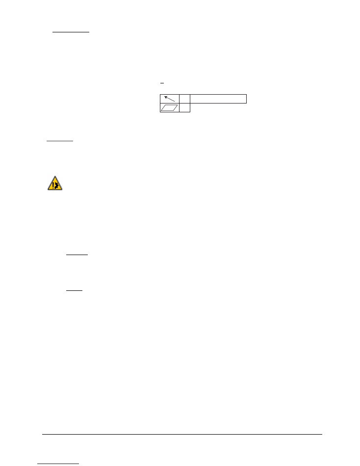
5.1 -
Customer Interface Specification
Customer friction flange specification:
§
Material:
Steel (150 to 250 HV) or Cast iron
§
Roughness:
< Ra 3.2
§
Finishing:
Dry phosphate (with manganese or zinc)
§
Geometric tolerances:
5.2 -
Brake Mounting
Reminder:
Precautions and safety measures must be read before any installation or maintenance of the brake.
Compliance with the instructions and values given by the documentation and marking of the unit is
imperative in order to ensure a proper functioning of the brake.
Avoid any impact or damage to the brake during handling.
Never lift the brake using the coil cables.
This brake is designed to work in clean conditions. Friction faces must be kept completely clean of
any oil, water, grease or abrasive dust.
-
Tighten the three transport screws CHc M8.
-
Put the hub into position on the customer’s shaft.
-
Mount the O-rings on the hub (see Fig. 1).
-
Engage the disc on the hub as illustrated in Fig. 1, the heel on the brake side.
Caution:
When installing and should the brake ever be taken apart, make sure that the friction disc
heel is the right way round when the brake is put back together (see Fig.1).
-
Engage the rear disc the heel on the brake side with the intermediate disc and the brake on the hub.
-
Line the brake up with the customer fixing flange, using the fixing screws.
NOTE:
Secure the fixing screws (safety washer or a thermoplastic liquid such as Loctite).
-
Tighten the 8 fixing screws CHc M12, star sequence tightening, to an initial torque of 50 Nm. The
supply of current to the brake should be switched off.
-
Switch on current to the magnet.
-
Tighten the 8 fixing screws CHc M12(Cs: 130 Nm ±10%). The supply of current to the brake should be
switched on throughout this operation.
-
Remove the three transport screws.
-
Make all the permanent electrical connections
0,1
Customer shaft axis
0,1
WARNER ELECTRIC EUROPE - Rue Champfleur, B.P. 20095, F - 49182 St Barthélemy d’Anjou Cedex
SM477gb - rev 04/16
10/15
6-
Electrical Connection
Brake
ERS VAR10 SZ 2500/---
operates on a direct current supply. Polarity does not affect the brake
operation.
All works on the electrical connections have to be made with power off.
Make sure that the nominal supply voltage is always maintained. A lack of power results in a
reduction to the maximum air gap.
When switching on DC-side the coil must be protected against voltage peaks, according
DIN VDE0580.
Emergency braking
: for emergency braking the switching OFF must be connected on DC current side,
in order to obtain short engaging time of the brake.
Service braking:
for service braking, the switching OFF and ON must be connected on AC current
side, in order to obtain silent switching.
The connecting wires must be thick enough to help prevent sudden drops in voltage between the
source and the brake.
Cable length
m
0 -> 10
10 -> 20
Cross section
mm²
1.5
2.5
Table 2
Tolerances on the supply voltage at the brake terminals: +10% / -15% (CEI 60038:2009:2009-06).
6.1 -
Microswitch Technical Data
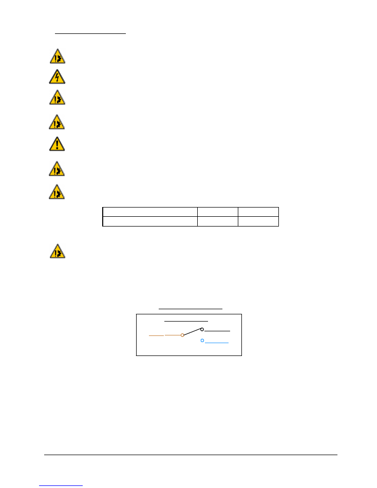
Microswitch connection
Switch Connection
Brown
Black (NC)
Blue (NO)
§
Current range:
10 mA à 100 mA at 24 Vdc
§
For maximum electrical lifetime of the microswitch ensure switching under resistive load
only.
WARNER ELECTRIC EUROPE - Rue Champfleur, B.P. 20095, F - 49182 St Barthélemy d’Anjou Cedex
SM477gb - rev 04/16
11/15
7-
Maintenance
7.1 -
Air Gap Checking
Check the air gap at each maintenance inspection.
This brake is intended for a static application as a safety brake. Any dynamic braking is restricted to
emergency and test braking. Normal use will not lead to any noticeable wear on the lining.
Under no circumstances, this device can replace the system case against the car overspeed in the
descending phase.
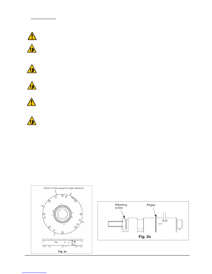
Air gap has to be measured at the 4 points at the circumference and at each braking circuit (see
Fig.
3
). If the maximum value of the air gap (see Table 1) is exceeded in one point, change the disc and
the O-ring.
Do not introduce the feeler gauge more than 10 mm into the air gap.
Avoid the springs and the dampers of noise.
Any modification made to the brake without the express authorisation of a representative of Warner
Electric, as far as, any use out of the contractual specification accepted by "Warner Electric", will
result in the warranty being invalidated and Warner Electric will no longer be liable in any way with
regard to conformity.
The customer must be careful to not alter the factory set parameters: Microswitch adjustment, air
gap adjustment and dampening system. This brake must not be dismantled.
-
Loosen the fixing screws slightly.
-
Slide into the airgap 4 feeler gauges 0,45 mm thick, or according Fig. 3a (put the feeler gauges near the
marks on the magnet).
-
Set the fixation screws to contact.
-
Adjust the adjusting screws, Fig. 3b.
-
Remove the 4 feeler gauges.
-
Tighten the fixation screws (refer to note point 5.2 Installation).
-
Carry out a few successive draws and releases.
-
Check the airgap at several points.
-
Repeat the process if necessary.
WARNER ELECTRIC EUROPE - Rue Champfleur, B.P. 20095, F - 49182 St Barthélemy d’Anjou Cedex
SM477gb - rev 04/16
12/15
7.2 -
Discs exchange
During maintenance, make sure that the driving mechanism is stopped and that there is no risk of
accidental starting. The intervention must be signaled and the work area delimited.
All intervention must be done by authorized and qualified personnel, having read and understood
this manual, using adapted procedures and professional tools. All intervention must be done
according the regulation of the country of the installation.
Warning
: It is mandatory that disassembling and assembling of the encoder is done according the
instructions of the drive manufacturer.
Warning
: not to damage the electric cables during the maintenance action.
This brake is designed to work in clean conditions. Friction faces must be kept completely clean of
any oil, water, grease or abrasive dust.
Customer friction flange must be also carefully cleaned.
-
Disconnect the brake electrically
-
Remove the fixation screws
-
Remove the brake
-
Clean the friction faces with a clean and dry cloth.
-
After the worn friction disc is replaced, assemble the brake according chapter 5.2.
7.3 -
Detection Checking
Any modification made to the brake without the express authorisation of a representative of Warner
Electric, as far as, any use out of the contractual specification accepted by "Warner Electric", will
result in the warranty being invalidated and Warner Electric will no longer be liable in any way with
regard to conformity.
The customer must be careful to not alter the factory set parameters: Microswitch adjustment, air
gap adjustment and dampening system adjustment. This brake must not be dismantled.
-
Switch ON the brake, the state of both microswitches must change.
-
Switch OFF the brake.
-
Insert a feeler gauge 0.2 mm in the nearest control zone of the microswitch.
-
Switch ON the brake, the state of both microswitches must not change.
WARNER ELECTRIC EUROPE - Rue Champfleur, B.P. 20095, F - 49182 St Barthélemy d’Anjou Cedex
SM477gb - rev 04/16
13/15
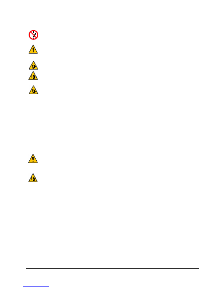
7.4 -
Detection setting
-
Slide a wedge 0,15mm thick close to the screw in the corresponding airgap.
-
Switch on the current and tighten the adjusting screw H M4 (7/flat) in contact with the microswitch
until you reach the commutation point.
-
Remove the wedge.
-
Check that it functions correctly by a few successive draws and releases.
Fig. 4
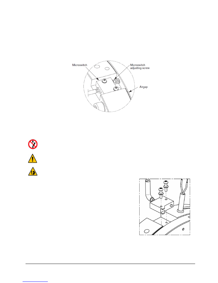
7.5 -
Microswitch exchange
During maintenance, make sure that the driving mechanism is stopped and that there is no risk of
accidental starting. The intervention must be signaled and the work area delimited.
All intervention must be done by authorized and qualified personnel, having read and understood
this manual, using adapted procedures and professional tools. All intervention must be done
according the regulation of the country of the installation.
Warning
: not to damage the electric cables during the maintenance action.
-
Unplug the microswitch
-
Remove the microswitch fixing screws
-
Replace the microswitch
-
Tighten the fixing screws to the torque of 0.8 N.m (±10%)
-
Re-connect microswitch wires (see chapter 6.1)
-
Set the detection as it is shown in the chapter 7.4
Fig. 5
WARNER ELECTRIC EUROPE - Rue Champfleur, B.P. 20095, F - 49182 St Barthélemy d’Anjou Cedex
SM477gb - rev 04/16
14/15
8-
Spare parts
Available spare parts for this brake are the following:
-
Friction disc
-
Microswitch
-
O-ring Kit
Please, join to your spare part request the following information:
•
Warner Electric Europe Reference
•
Production Number
•
Serial Number
•
Production Date
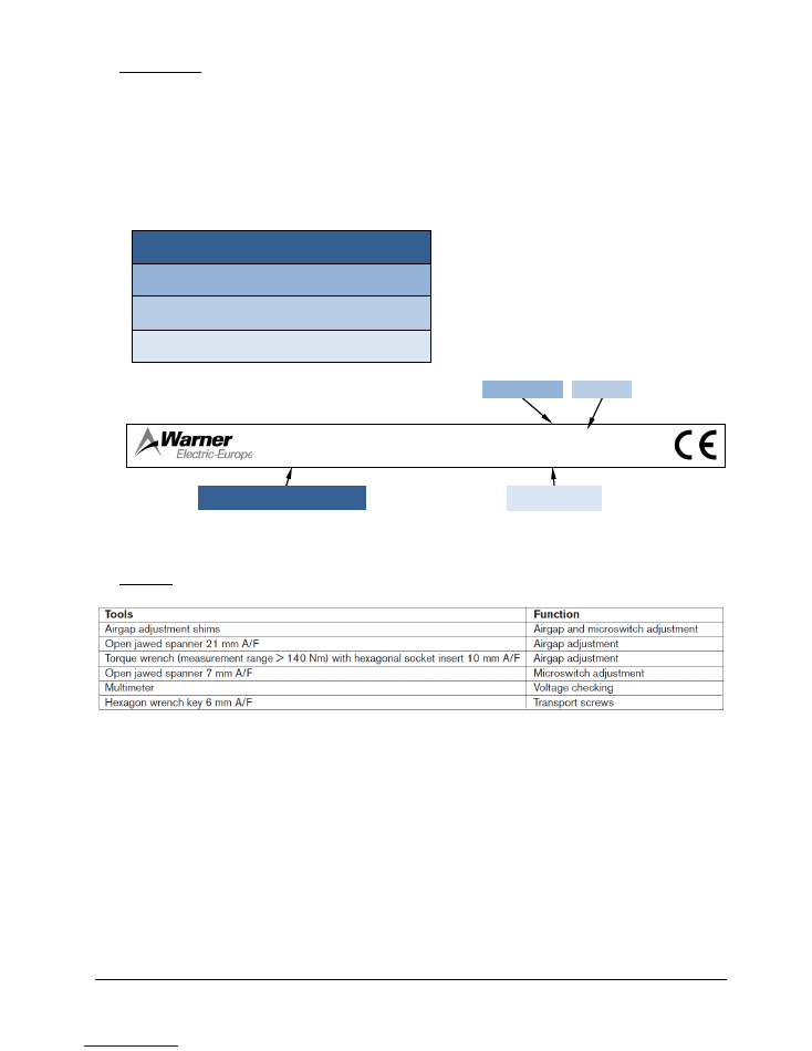
9-
Tooling
207/103VDC 88/21 W
777888-1
303xxxxx
CM8
Production N°
Sérial N°
Production Date
Warner Electric Europe Reference
WARNER ELECTRIC EUROPE - Rue Champfleur, B.P. 20095, F - 49182 St Barthélemy d’Anjou Cedex
SM477gb - rev 04/16
15/15
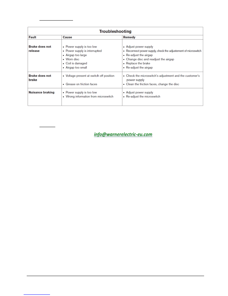
10-
Troubleshooting
11-
Contact
Any question? You can contact us at:
This translation is for information only. In case of discrepancy between this version and the original in French, only the text of the French
version prevails.
All rights reserved to change without prior notice.
www.warnerelectric-eu.com
Rue Champfleur, B.P. 20095
F- 49182 St Barthélemy d’Anjou Cedex
+33 (0)2 41 21 24 24
P-2107-WE-A4 SM477GB 9/18