Full Text Searchable PDF User Manual
MANUAL
|
FRONT HUB MIG70
www.tune.de
As of May 2015
Page 1 of 9
BUILT TO
ENJOY NATURE
BORN IN THE BLACK FOREST
Front Hub
MIG70
M A N U A L
as of May 2015
Number of holes
12, 16, 18, 20, 24, 28, 32
Disc mount
none
Build-in-with
100 mm
Axle diameter
17 mm
Colours
black, silver, red, gold, blue, green, orange, froggy-green
and white (powder-coated)
Bearings hub body
2 specific Tune grooved ball bearings (2 x 61803)
Sealing
dust cap, washer and rubber lip seal
Weight limit
none
Material:
Flange
aluminium, CNC machined
Axle
aluminium, CNC machined
Endcaps
aluminium, CNC machined
Inner sleve
aluminium, CNC machined
MANUAL
|
FRONT HUB MIG70
www.tune.de
As of May 2015
Page 2 of 9
Instructions
General:
• Before every ride, make sure that your tune product is in a good condition and functioning properly. If there
seems to be any irregularities the product should not be used. Contact your retailer for help.
• The Quickrelease must be mounted properly.
• Never clean your Tune products directly with high water pressure (pressure cleaner) and do not use ag-
gressive detergents.
• Only use tires that suit the rim, pay attention not to exceed the maximum tire pressure of the rim and tire.
Maintenance:
The hub should be maintained at least once a year. If used in extreme conditions (rain, mud, salted streets,
transport in the rain) regularly, the hub should be maintained more often. A regular service supports the tech-
nical condition, as well as the durability of the hub.
What does the regular maintenance include?
•
The mounted hub should be cleaned. Afterwards it should be undertaken a detailed visual and technical
examination.
•
When disassembled, the bearings should be examined. The maintenance is described in detail below.
Lacing:
•
The hub is constructed for radial lacing or crossed lacing.
•
The 32 and 36 hole version has to be laced crossed.
•
If the MIG70 hub is gets laced radially the spoke heads have to face outwards.
•
The MIG 70 flanges have been designed to automatically distribute the tension among the spokes evenly
during the lacing process. There will be no more movement, of the flanges relative to each other, once the
spokes all have been tensioned (exerting an overall pulling force of several tons).
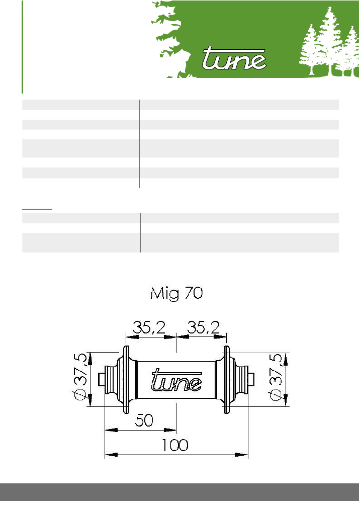
MIG70:
The highest permitted spoke tension is 1000 N.
Pitch circle diameter Ø
37.5 mm
Distance hub flange to wheel center line (l / r) 35.2 / 35.2 mm
Spoke hole diameter Ø
2.4 mm
MANUAL
|
FRONT HUB MIG70
www.tune.de
As of May 2015
Page 3 of 9
Maintenance
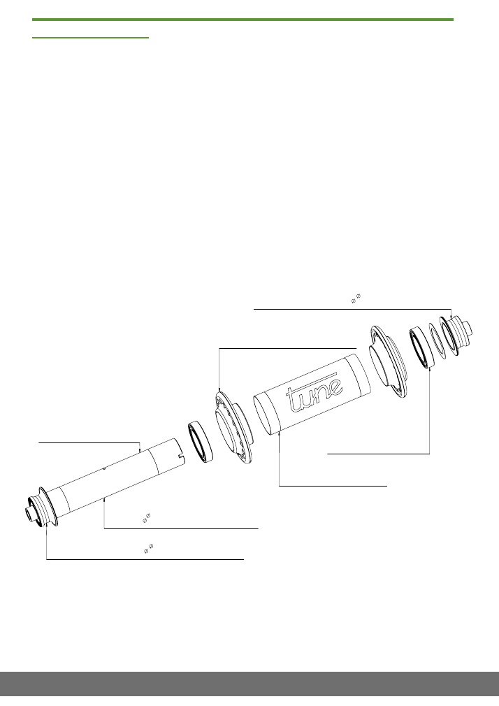
Construction of the hub:
This hub is built up from firmly connected parts, i.e. the axle goes all the way through, with endcaps at
both sides, and all parts are fixed exactly in place.
Tune uses specific bearings not available from any other manufacturer. The bearings distinguish
themselves by there unusual high amount of special grease and a radial play adjusted for the use.
The bearings have a double slid sealing, the hub therefore will run comparatively sluggishly when
new. This will change after the first rides, when the grease has been dispersed evenly in the ball-bear-
ings and the seals are working optimally.
Spare parts can be ordered through your local Tune retailer.
Aluröhrchen für Mig70 VR-Nabe, Farbe /
hub-body-bushing for Mig70 front-hub, color
VN01167(+Farbcode/color code)
Endkappe für King/Princess/Mig70/Dörte, 17mm, 10.0mm, links+rechts, schwarz
end-cap for King/Princess/Mig70/Dörte, 17mm, 10.0mm, left+right, black
NZ0304sw
Einreihiges Rillenkugellager 61803 2RS C3 /
single-row ball bearing 61803 2RS C3
NZ1509
Einreihiges Rillenkugellager 61803 2RS C3/
single-row ball bearing 61803 2RS C3
NZ1509
Endkappe für King/Princess/Mig70/Dörte, 17mm, 10.0mm, links+rechts, schwarz
end-cap for King/Princess/Mig70/Dörte, 17mm, 10.0mm, left+right, black
NZ0304sw
Aluminiumachse 17mm für King/Princess/Mig70/Dörte15, silber
aluminium-axle 17mm for King/Princess/Mig70/Dörte15, silver
NZ0002si
Mig70
BVN01 (+Lochzahl/number of spoke holes)(+Farbcode/color code)
Flansch für Mig70 VR-Nabe, Lochzahl, Farbe /
flange for Mig70 front-hub, number of spoke holes, color
VN001(+Lochzahl/number of spoke
holes)(+Farbcode/color code)
Stand: Oktober 2013
as of: October 2013
MANUAL
|
FRONT HUB MIG70
www.tune.de
As of May 2015
Page 4 of 9
fig.1
Disassembly and assembly of the hub:
Important notes:
• All contact surfaces, except between the bearings and the hub body, should be greased.
• Always remember the exact position of all parts.
• Please contact your dealer, if you feel insecure, don´t have appropriate skills or the needed
equipment.
Needed tools / material:
• tool kit Tune Tool 08 (No. BWZ0000)
• plastic hammer
• an rob (old Quickrelease axle)
• hot air blower
• vernier caliper
•
1
Grease (we recommend Molykote Rapid Plus Paste, alternative bearing grease)
•
2
Glue (e.g. 3M Scotch-Weld TL-70, Loctite 641)
This manual leads you through the complete disassembly, assembly and adjustment of the hub. Not all
steps have to be carried out maintaining the hub.
If you only want to adjust the bearing play you can start with the first step
„Removing the endcap“
after-
wards you can continue with the step
„Setting the bearing play“.
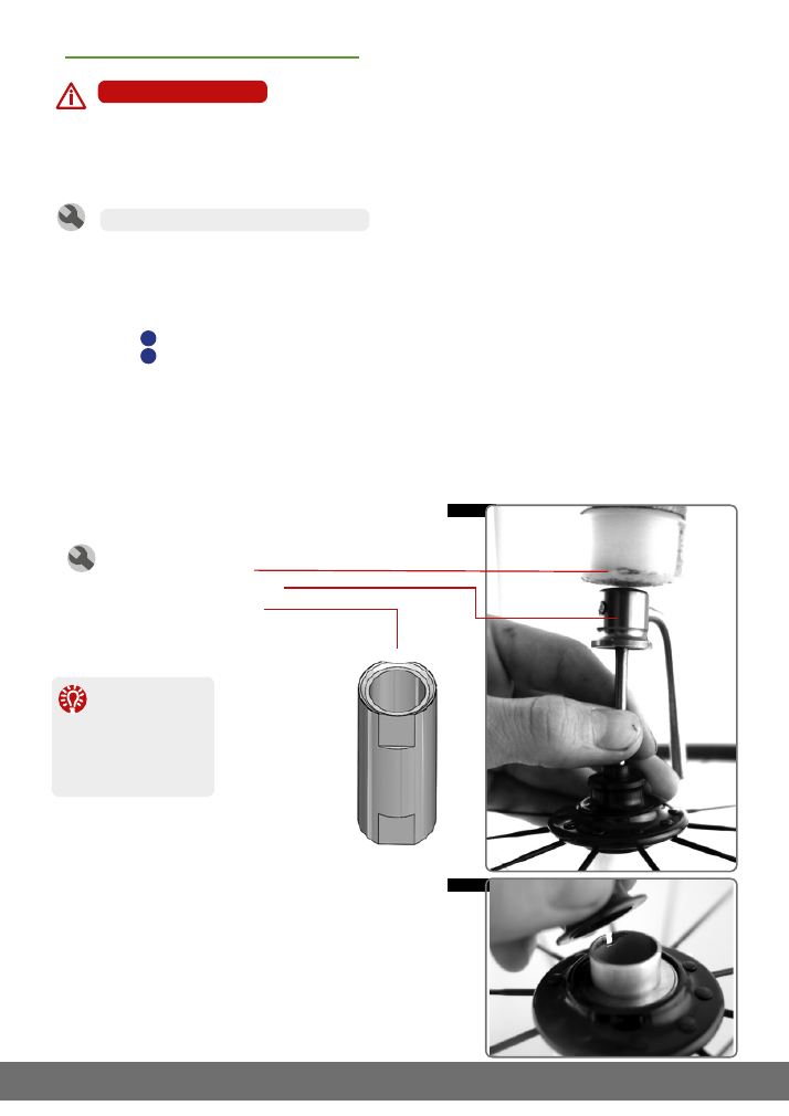
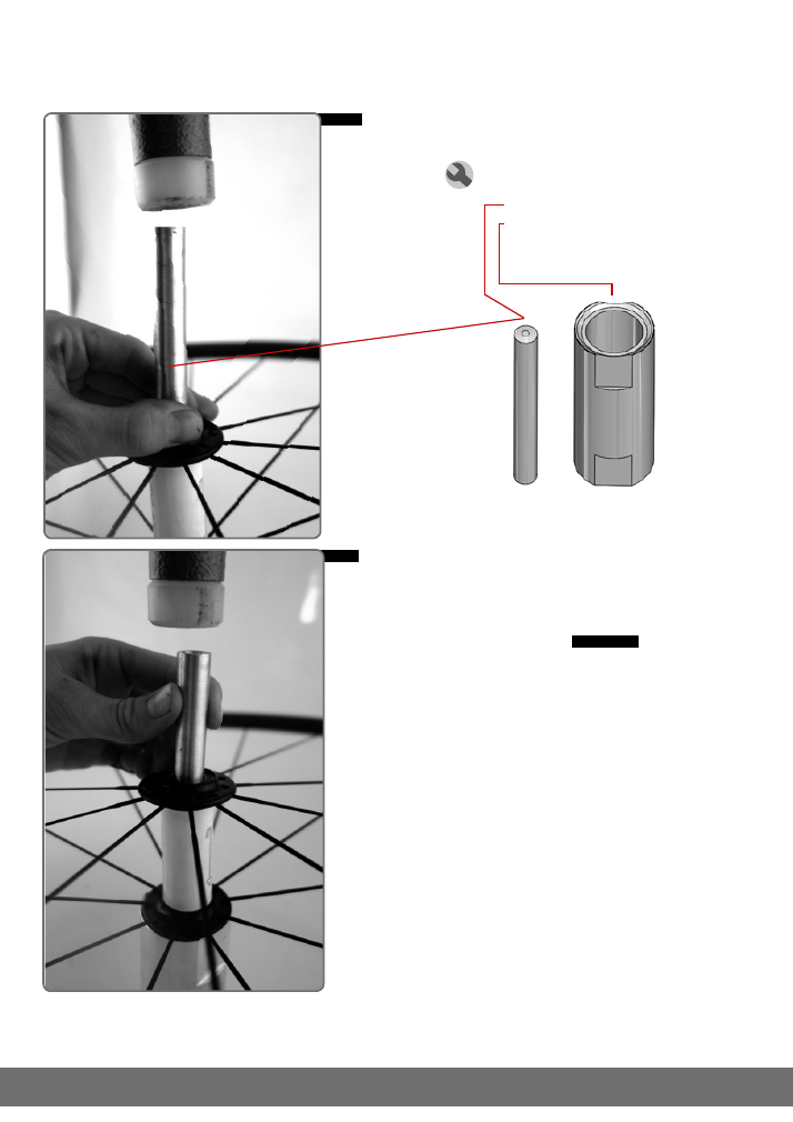
The hub gets placed on the main tool TT08.1.
An Quickrelease axle gets pushed through the
left endcap into the hub axle, so that it touches
the inner side of the right endcap.
The right end cap can now be pushed of the
axle by hitting the Quickrelease with the plastic
hammer.
Be careful to not loose the distances, which
are placed between the endcap and bearing.
Needed tools:
• plastic hammer
• old Quickrelease axle
• main tool TT08.1
1
Removing the endcap
fig.2
TT08.1
The right side of the
hub is next to the
“e” in the Tune logo.
(see graphic on p.3)
Tip:
MANUAL
|
FRONT HUB MIG70
www.tune.de
As of May 2015
Page 5 of 9
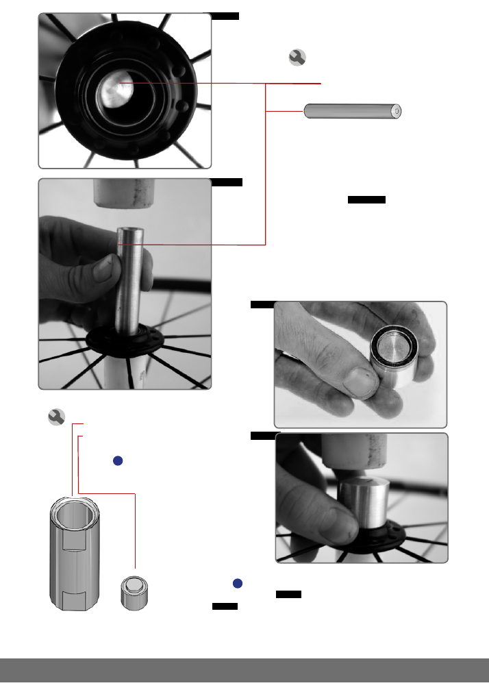
Place the hub on the main tool TT08.1.
Now the axle can be pushed out using the to the
Tool TT08.2 and a hammer.
fig. 3 & 4
If the hub is not laced, the flange (including the
pressed-in bearings) as-well as the inner sleeve
can be separated already.
fig.3
2
Removing the axle
Needed tools:
• plastic hammer
• TT08.2
article No.
WZ0202
• TT08.1
article No
.
WZ0200
fig.4
TT08.1
TT08.2
MANUAL
|
FRONT HUB MIG70
www.tune.de
As of May 2015
Page 6 of 9
The cleaned bearing seat gets covered with a thin layer of
glue
3
. The bearing gets pressed in with some light hits
from a hammer
fig. 8
, using the correct sized fitting stamp
fig. 7
.
Pay attention to not cant the bearings and always only strain
the outer ring of the bearing.
5
Installing a new bearing
Needed tools:
• TT08.1
No. WZ0200
• TT08.14
No. WZ0209
• plastic hammer
• glue
2
fig.7
fig.8
TT08.1
TT08.14
fig.6
fig.5
4
Removing the bearings
Needed tools:
• TT08.1
• TT08.2
•
TT08.2
Place the hub on the main tool TT08.1.
Now the bearings can be pushed out us-
ing the tool TT08.2 and a plastic hammer.
Always dispense the force all around the
bearing to not damage both the bearing
and the hub body.
fig. 5 + 6
MANUAL
|
FRONT HUB MIG70
www.tune.de
As of May 2015
Page 7 of 9
6
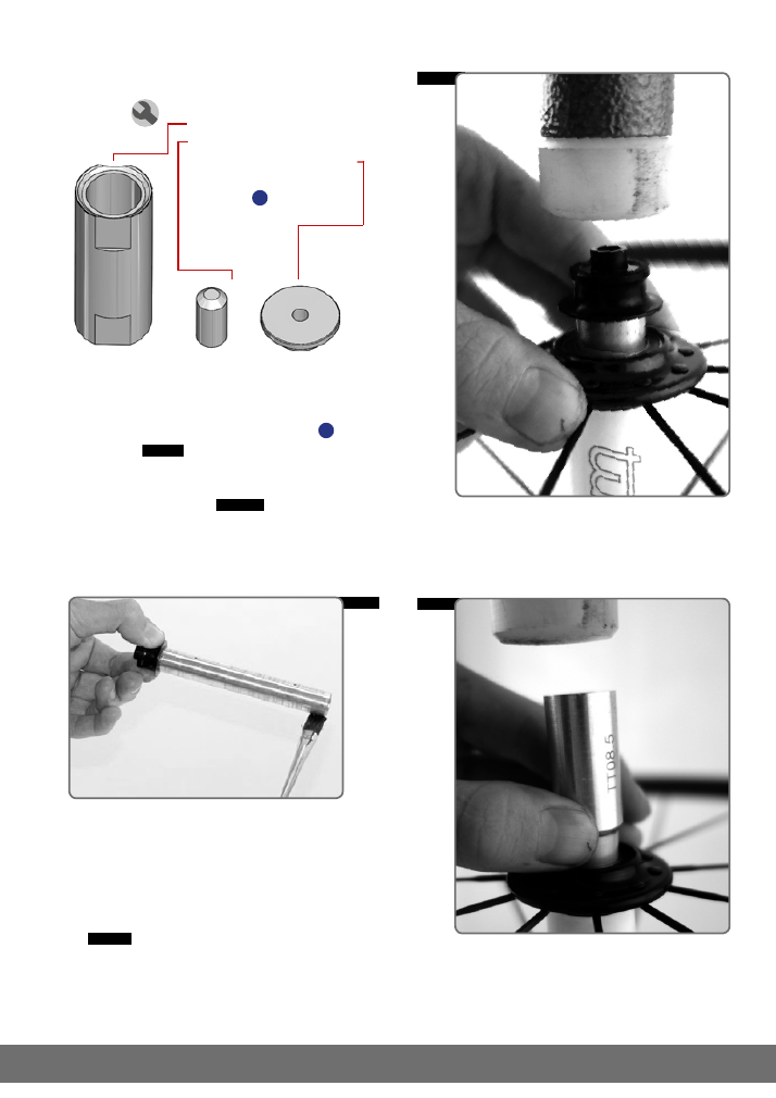
Reassembling the hub
Needed tools:
• TT08.1
article No. WZ0200
• TT08.5
article No. WZ0218
• TT08.9
article No. WZ0204
• plastic hammer
• grease
1
fig.10
fig.9
TT08.1
TT08.5
TT08.9
Release axle and bearings
Place the hub on the main tool with the extra attach-
ment TT08.9, that only the left endcap touches the tool.
Using the tool TT08.5 and a plastic hammer hit the axle
softly.
fig.11
By doing so, strain is taken of the axle
and the bearings.
fig.11
The axle gets slightly covered with grease
1
in the
contact areas.
fig.10
The hub gets placed on the main tool TT08.1. Using
the tool TT08.5 and a plastic hammer the axle gets
pushed back into the hub.
fig.9
MANUAL
|
FRONT HUB MIG70
www.tune.de
As of May 2015
Page 8 of 9
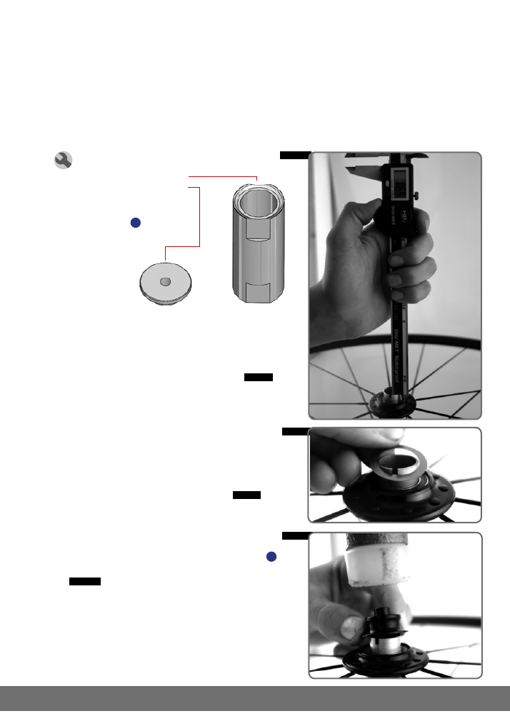
fig.13
fig.12
Needed tools:
• TT08.1
No. WZ0200
• TT08.9
No. WZ0204
• plastic hammer
• vernier caliper
• grease
1
Now the open end of the axle on the right side has to be meas-
ured. With the depth gauge of a vernier caliper measure the
axle from the inner ring of the bearing to the end of the axle.
The measurement has to be extremely precise, we recom-
mend to repeat the measurement a couple of times.
fig.12
TT08.1
TT08.9
Reasons for bearing play can be worn bearings, a damaged axle or just the adjustment. A certain bearing
play is normal and enables a soft and smooth rotation.
The axial bearing play is adjusted with washers. These are available in 0,1mm (NZ1604), 0,15mm (NZ1605)
and 0,2mm (NZ1606) width. The washers are placed between the outer freewheel bearing and the right
endcap. We adjust the bearing play during production for every hub in manual labour. With wear, or when
new bearings are installed, the bearing play has to be readjusted.
7
Setting the bearing play
fig.14
From the measured length (e.g.: 8.4 mm) subtract the
depth of the endcap (8.0 mm). The difference is the axial
bearing play (here 8.4 - 8.0 = 0.4 mm).
The optimal axial bearing play amounts 0.15-0.20mm. The
difference between the measured open end of the axle
(e.g.: 8.4 mm) and the depth of the endcap (8,0 mm) has
to be adjusted to 0.15-0.20 mm using washers.
fig.13
The axial bearing play is adjusted perfectly, if the length, of
the open end of the axle, with washers is set to 8.15-8.20mm.
To finish of, the endcap is slightly covered with grease
1
on the inside. Now it can be pushed back on using a plastic
hammer.
fig.14
Now the wheel is usable again.

MANUAL
|
FRONT HUB MIG70
www.tune.de
As of May 2015
Page 9 of 9
© Tune U.Fahl e.K
.
BUILT TO ENJOY NATURE
BORN IN THE BLACK FOREST
Tune U. Fahl e.K.
Im Mittelfeld 18
|
79426 Buggingen
service@tune.de
www.tune.de
Outside of Germany please contact your local distributor.
Service
Warranty:
Tune grants a two year warranty from the date of purchase on material defects and production errors. On
bearings, rims and spokes we grant a one year Warranty, as these are wear parts. Claims can only be made
if a copy of an original dealer invoice is presented.
There is no claim for warranty services in case of:
•
normal wear
•
improper use or careless treatment
•
disregard of service instructions
•
inappropriate repair, assembly, or maintenance works or negligence
•
defects caused by wrong wheel building (spoke patterns, spoke crossings, spoke tension, etc.)
Warranty claims have to be sent to the local Tune distributor and are subject to the assessment of Tune.
Based on this warranty, the company Tune is not liable for compensation, especially not for indirect damage
caused by accidents, collateral damage and consequential damage. All anodized parts can bleach in sunlight.
Crash Replacement:
Tune offers a Crash Replacement in addition to the legal warranty. The service can be engaged if your Tune
product is damaged and not be ridable any more, due to a crash, accident or overload .
Conditions:
•
Due to our huge products variety, the discount we can give, is assessed individually for every case.
•
The damaged part is replaced by the same model. Tune reserves the right to replace the damaged part
with an equal alternative.
•
The damage has to affect the functionality of the component (optical damage is excluded).
•
Damaged parts pass into the ownership of Tune.
•
The Crash Replacement offer does not cover the costs of transport and labour.