Full Text Searchable PDF User Manual

e
-
ASK
E
lectronic
A
ccess
S
ecurity
K
eyless-entry
e-ASK Keyless-entry System
Installation & Instructions
C
C
A
A
N
N
M
M
u
u
l
l
t
t
i
i
p
p
l
l
e
e
x
x
S
S
y
y
s
s
t
t
e
e
m
m
4
6
June 2008

2
Table of Contents
Introduction .............................................................................................3
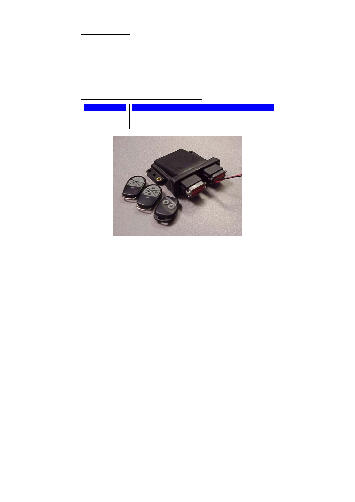
Cargo e-FOB Operation and Features ..................................................3
Non-doorbell e-PAD Operation and Features ......................................4
Locking doors with keypad ...................................................................4
Secure Operations................................................................................4
e-
ASK
CAN DIP Switch Configuration -...............................................5
Additional Features.................................................................................5
Dome/Porch Light Activation ................................................................5
e-
PAD
Anti-tamper Deactivating Feature .............................................5
Trim Pot Variable Resistor...................................
錯誤
!
尚未定義書籤。
Keypad Learn Wire ...............................................................................6
Status LED............................................................................................6
Miscellaneous I/O Module Features .....................................................6
Door locking and unlocking ..............................................................6
Timed Dome/Porch Light Activation ................
錯誤
!
尚未定義書籤。
Teaching Additional Transmitter Fobs .................................................7
Teaching Keypad New Authority / Access Codes ...............................9
Assign New Access Codes.................................................................10
Wiring Assignments……………………………………………………..…11
Troubleshooting ....................................................................................12
3
Introduction
This manual provides the necessary information for the proper installation
and use of Tri
Mark
’s CAN
e-ASK
system. The
e-ASK
system comes with
the following components:
•
e-FOB
(keyless entry radio frequency [RF] FOB transmitter and
receiver)
•
e-PAD
keypad user interface
e-FOB Operation and Features
Button
Function
Entry Lock
Locks entry door and arms security system.
Entry Unlock
Unlocks entry door and activates the porch light.
Note:
•
The FOB transmitters and receiver are shipped programmed.
After making all necessary wiring connections (see page 11 for
wiring information), the e-
FOB
system will function as shown.

4
Non-doorbell e-PAD Operation and Features
The e-
PAD
is shipped with default authority and access codes. Unless the
OEM or dealer has changed default codes, the authority and access
codes are as follows:
Access code:
Digit 1
Digit 2
Digit 3
Digit 4
Digit 5
1/2 3/4 5/6 7/8 9/0
Authority code:
Digit 1
Digit 2
Digit 3
Digit 4
Digit 5
7/8 7/8 7/8 7/8 7/8
Locking doors with keypad
Press and hold down the (1 / 2) or (1) button for 1-2 seconds. An access
code is not needed to lock the doors.
Secure Operations
Entering a valid 5-digit access code enables secure operations. After
entering an access code, the keypad is enabled for 5 seconds and an
additional button press initiates a secure operation, such as unlocking the
doors.
Notes:
•
The authority code does not allow for secure operations. It is
only used to assign access codes (see page 9 for information
on setting access codes).
•
If an unassigned button or no button is pressed while the
system is enabled, the keypad reverts back to disabled state.
•
The secure keypad operations are set depending on the
system configuration.

5
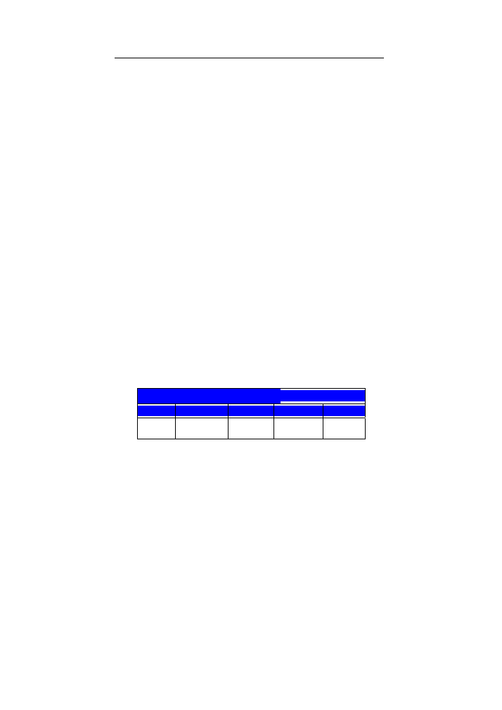
e-ASK CAN DIP Switch Configuration -
•
DIP switches 1-3:
The settings of DIP switches 1-3 define CAN address of the IO RF receiver
module. The setting a unique address is required if multiple modules are
used on CAN network. If only 1 module is used on network then all DIP
switches should be set to default ON position.
•
DIP Switch 1: On
•
DIP Switch 2: On
•
DIP Switch 3: On
•
DIP switches 4-6:
The setting of DIP switches 4-6 define configuration of the IO RF receiver
module. Different configurations of provide different functionality for
keypad and interior switches. Spartan’s setting is as follows:
•
DIP Switch 4: On
•
DIP Switch 5: Off
•
DIP Switch 6: Off
•
DIP switch 7:
The setting of DIP switch 7 defines the type of remote fob transmitter,
either standard fob or cargo fob. Spartan would have this DIP switch on.
•
On: Cargo fob
•
DIP switch 8:
The setting of DIP switch 8 defines the type of CAN protocol, either RV-C
or SAE J1939. Spartan would have this DIP switch on.
•
On: SAE J1939
Additional Features
Dome Light Activation
The dome light is activated for a timed duration (20 seconds) whenever
the system is unlocked from keypad or FOB transmitter.
e
-
PAD Anti-tamper Deactivating Feature
After repeated attempts to enter incorrect codes (20 button presses
without enabling), the keypad enters an inactive mode that disables button
for 1 minute. This helps prevent undesired access by entering random

6
codes. No beep will sound with button press while the system is disabled.
Keypad Learn Wire
The yellow input wire is used to reset the keypad to assign a new authority
code. See page 9 for further information on teaching keypad a new
authority code.
Status LED
LED flashes at power-up and can provide other trouble shooting
diagnostics codes
Miscellaneous I/O Module Features
Door locking and unlocking
A short single pulse output provides locking and unlocking operation to the
entry doors (zone 1). The compartment doors are locked and unlocked
with a single pulse. The locking and unlocking pulses have opposite
polarities. Locking and unlocking operations are activated via vehicle
switch inputs or according to
e-PAD
and
e-FOB
instructions.

7
Teaching Additional Transmitter Fobs
There are 2 ways that one can put the receiver into learn mode. The first
requires that a CAN keypad be connected to the network. This option
allows the receiver to be put into train mode without accessing the module.
The 2
nd
option requires one to have access to the receiver, but a keypad is
not required.
Option 1 (if CAN keypad is connected to network):
1. Hold middle (5/6) button of keypad for 5 seconds. The keypad will
beep and the LEDs will flash.
2. Enter authority code buzzer stays on.
3. Hold 9/0 for 5 seconds. A double-beep plays.
4. The receiver module is now in FOB Learn Mode (The LED under
the receiver enclosure will be blinking rapidly-this will not be
visible unless the enclosure cover is removed)
5. Next press lock button of each fob (up to 4) that should be
synched. (LED stays solid for 2 seconds as each one is learned.)
Press the fob button for 0.5-2.0 seconds. Do not attempt to synch
subsequent fobs until minimum of 3 seconds.
6. After 60 seconds of FOB button inactivity, or by simply pressing
any key on the keypad, you will hear the successful indication (4
quick beeps) and the I/O module will reboot and address claim
again to go back to normal operation.
Option 2 (if no CAN keypad is connected to network):
1. Remove power from door module
2. Open up door module enclosure
3. Move DIP switches 4-6 to the “ON” position. Make sure that the
antenna module PCB is installed.
4. Connect door module to CAN network
5. Connect power to door module (8 pin connector)
6. Wait about 5 seconds. Module will perform a start up sequence
during this time interval. After start up sequence LED will continue
to flash.
7. Press any fob button until LED pattern changes (longer -0.5
second flash), then release. This synchs the first fob transmitter.
8. Press any fob button of 2
nd
fob, LED pattern changes immediately.
This synchs the 2
nd
fob transmitter.
9. Repeat above step 8 until all fobs are synched (up to 4 fobs)
10. Remove power and CAN connector from door module
11. Move DIP switches 4-6 to normal position and verify DIP switches
1-3 are in proper position. Further information on DIP switches is
above.
12. Reassemble enclosure.

8
13. Reconnect CAN connector.
14. Reconnect power to door module.
15. Verify that fobs are synched to the door module and that range is
of RF transmission is acceptable. Door module needs to be
connected to a valid CAN network (2+ modules on network) for
verify functionality.
Please Note:
Up to 4 transmitters can be synched with a door module.
9
Teaching Keypad New Authority / Access Codes
When you assign a new authority code, you delete the existing authority
code as well as any access codes.
Note:
The authority code you assign following these instructions also
becomes an access code saved to the 1/2 button.
1. Connect yellow learn wire of keypad to ground There will be
three-second beep.
2. Enter a new five-digit code-this will be your access and authority
code.
3. Enter the new code again.
4. The existing code will only be erased if a new code is assigned.
5. The code is stored in position one.
Important:
Authority and access codes should not be the same. If
someone figures out an access code and discovers it to be an authority
code as well, they can then create their own access code and gain
entrance to your vehicle.
Once resetting the keypad, your next step should be to create a new
access code and store it in position one so as to ensure the access code is
no longer the same as the authority code.
Notes:
•
The authority code is to be controlled by individuals (owners of
vehicle, fleet manager, etc.) who manage the distribution of
access codes to vehicle users.
•
The authority code should be changed when the vehicle is sold.
•
The authority code does not enable secure functions (lock/unlock
doors, etc.) it is only used to assign access codes.
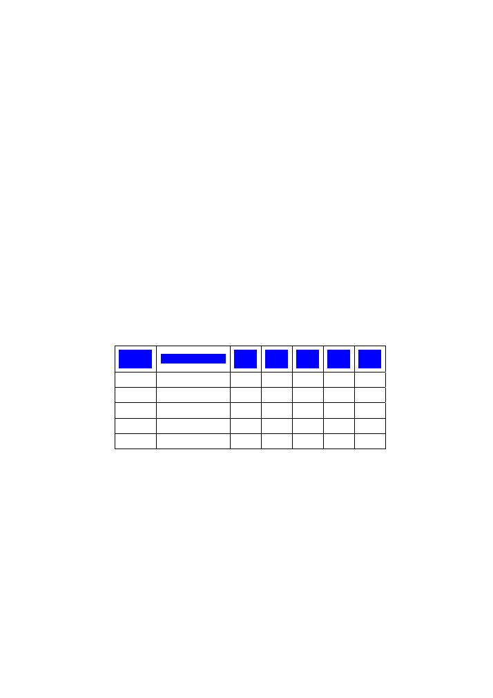
The following area can be used to document the authority code:
Authority Code
Digit 1
Digit 2
Digit 3
Digit 4
Digit 5
10
Assign New Access Codes
With a valid authority code (see pages 4 and 9), an access code can be
programmed with the following instructions.
1. Press the (5/6) button for 5 seconds, the keypad will beep. The
backlighting LED of the keypad will flash indicating the learn
mode.
2. Enter in the 5-digit authority code (see pages 4 and 9). Keypad will
provide a long beep that will stop after you have defined an
access number.
3. Press and release the button that corresponds to the access
number. For example, press (1/2) button for access #1 and press
(3/4) button for access #2. During this activity you are defining 1 of
5 access numbers. A subsequent code will be assigned to this
access #. The keypad will provide a confirmation beep after this
single button press.
4. Enter in your new 5-digit access code. The keypad will provide
confirmation beeps.
5. Re-enter new access code. The keypad will provide confirmation
beeps.
Repeat process to assign additional access codes.
Up to 5 different access codes can be assigned at one time. As additional
access codes are defined, pre-existing access codes are overwritten. For
example, if a new access code is assigned for access #3, the previous
access #3 code is no longer valid.
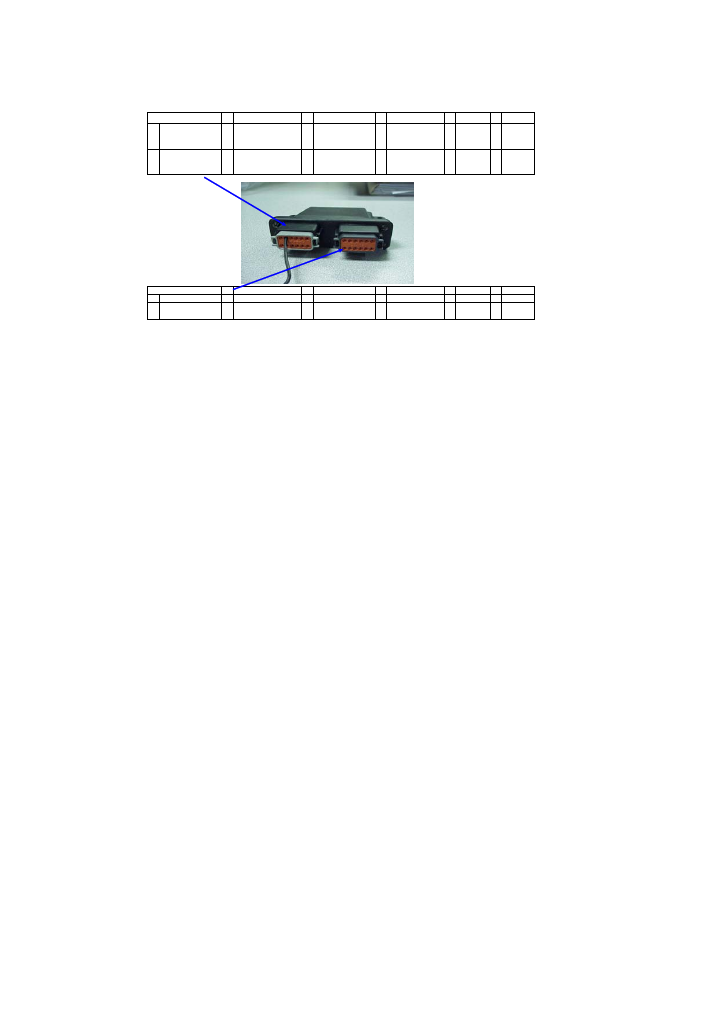
The following area can be used to document the access code
assignments.
Access
#
User Name
Digit
1
Digit
2
Digit
3
Digit
4
Digit
5
1
2
3
4
5
11
Wiring Assignments
Deutsch Enclosure Style
Gray Left Header
1
Courtesty Dome
Light Output
2
Antennae pin (solid
core wire
recommended)
3 CAN Low
4 Entry lock output
5 CAN High
6 Ground
12
Entry lock input (5)
11 Window UP input (1)
10
Window Down Input
(2)
9
Entry unlock input
(6)
8
Entry
unlock
output
7 Power
Black Right Header
1 Ground
2 Door ajar input
3 Not assigned
4 prog in 10
5 prog in 9
6 prog in 8
12 Power 11
Bank D Window
DOWN (B)
10
Bank D Window UP
(A)
9 prog in 7
8 prog in 4
7 prog in 3
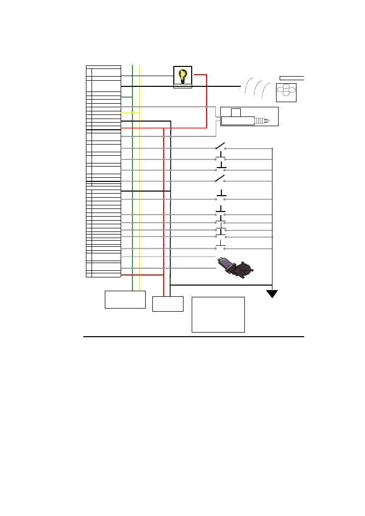
12
Gray Left Header
1
Courtesty Dome
Light Output
2
Antennae pin (solid
core wire
recommended)
3
CAN Low
4
Entry lock output
5
CAN High
6
Ground
7
Power
8
Entry unlock output
9
Entry unlock input
(6)
10
Window Down Input
(2)
11
Window UP input
(1)
12
Entry lock input (5)
Black Right Header
1
Ground
2
Door ajar input
3
Not assigned
4
prog in 10
5
prog in 9
6
prog in 8
7
prog in 3
8
prog in 4
9
prog in 7
10
Bank D Window UP
(A)
11
Bank D Window
DOWN (B)
12
Power
Battery
Remote Fob Transmitter
CAN per SAE J1939-15.
Terminating resistors
provided in vehicle harness
Notes:
1) All inputs are active at ground.
2) Motor outputs rated at 13 amp
continous sourcing
3) Dome light 2 amps ground
4) Battery power 9-16 VDC.
5) Antennae solid 18 AWG

13
Troubleshooting
Problem Description
Possible Solution
e-FOB Hints
Verify power to the I/O module and RF
receiver.
Button press does not provide
correct operation
Re-teach the FOB transmitter to the
receiver.
Mount RF receiver away from enclosed
metal areas and fully extend antennae.
No operation or intermittent
operation
Check FOB transmitter battery voltage.
Batteries may need to be changed
every 1-2 years depending on usage.
One particular e-
FOB
function
does not work.
Check wire connection of affected
function at RF module, wiring harness,
and I/O module.
e-PAD Hints
Verify power to the I/O module.
No response with button press
Verify that keypad cable is connected.
(rest of system will function)
Verify that code has not been changed.
Reassign keypad with instructions
starting on pages 9-10.
Access code is not recognized
Confirm use of an access code, not the
authority code.
Key fob works correctly, keypad
beeps, but no output
Cycle power to I/O module. Check
power connections.
Keypad beeps continually
Problem is detected on the
communication network (CAN). Check
that network is valid by confirming that
other modules are plugged into network
and that terminating resistors are correct
value and are installed.
Verify DIP switches on IO module are
set to correct configuration setting.
Unexpected operations occurs
Verify keypad configuration is correct.

14
e-ASK I/O Module Hints
No response in any system
element. No LED flash (LED is
under enclosure cover).
Verify power to the I/O module.
Unexpected operations occurs
Verify DIP switches are set to correct
configuration setting.
No response in any system
element. LED flashing (LED is
under enclosure cover).
I/O module is detecting problem with
communication network (CAN). Check
that network is valid by confirming that
other modules are plugged into network
and that network terminating resistors
are correct value and are installed.

XV
FCC ID: TV2EFOBII
FCC Compliance and Advisory
Statement
This device complies with Part 15 of the FCC rules. Operation is
subject to the following two conditions:(1) this device may not cause
harmful interference, and (2) this device must accept any
interference received, including interference that may cause
undesired operation.
This equipment has been tested and found to comply with the limits for a
Class B digital device, according to Part 15 of the FCC rules. These limits
are designed to provide reasonable protection against harmful
interference in a residential installation. This equipment generates, uses
and can radiate radio frequency energy and if not installed and used in
accordance with the instructions, may cause harmful interference to radio
communications. However, there is no guarantee that interference will not
occur in a particular installation. If this equipment does cause harmful
interference to radio or television reception, which can be determined by
turning the equipment off and on, the user is encouraged to try correct the
interference by one or more of the following measures:
1.Reorient the receiving antenna.
2.Increase the separation between the equipment and receiver.
3.Connect the equipment into and outlet on a circuit different from that to
which the receiver is connected.
4.Consult the dealer or an experienced radio/TV technician for help.
Any special accessories needed for compliance must be specified in the
instruction manual.
Warning:
A shielded-type power cord is required in order to meet FCC emission limits and also to
prevent interference to the nearby radio and television reception. It is essential that only the
supplied power cord be used. Use only shielded cables to connect I/O devices to this equipment.
CAUSION:
Any changes or modifications not expressly approved by the
party responsible for compliance could void your authority to operate the
equipment.