Full Text Searchable PDF User Manual
Easy touch Easy warm
Thermostat Instruction
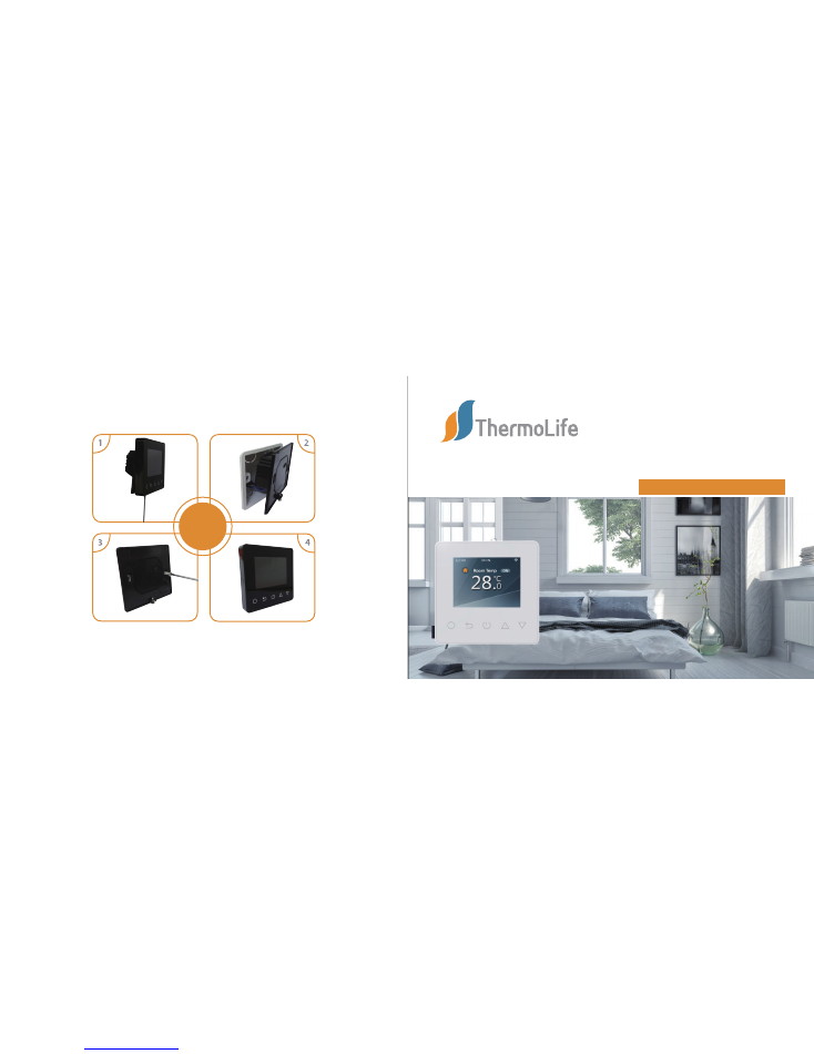
INSTALL
APP for ET-81W
01
Description
03
Technical specification
04
Display symbols
05
WiFi connection
(
Only for ET-81W
)
06
Function & User operation
07
Advanced setting
09
Dimension
10
Installation and wiring instructions
08
Troubleshooting
02
Main function
Table of Contents
01
01
01
02
03
05
10
12
12
13
MAIN FUNCTIONS
DESCRIPTION
Supply voltage: 85-265V 50/60Hz
Maximum switching current: 15A
Power consumption query
Holiday function
Time display
Hold function
Key-lock
Off time frost protection
Floor high temperature protection
Sensor selection
TECHNICAL SPECIFICATION
IP rating: IP21
Standby power:
<
2W
Wire diameter: ≤2.5mm²
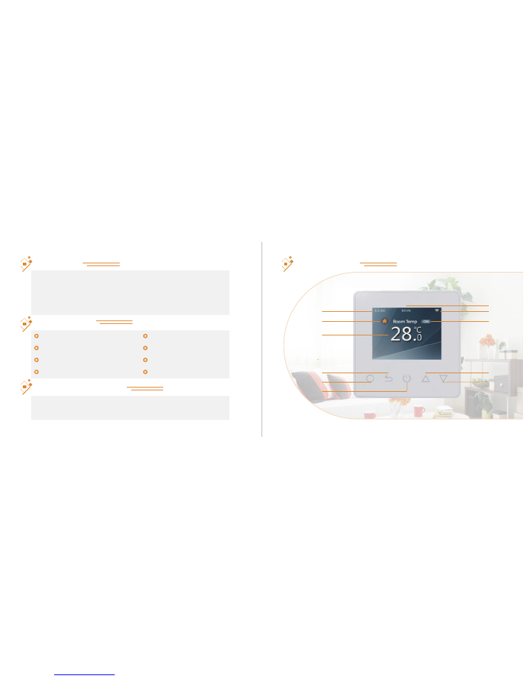
DISPLAY SYMBOLS
The ET-81 is an electronic programmable timer thermostat used for controlling
electrical floor heating elements. The thermostat is designed for fixed installation
only and can be used for both direct heating of the entire room and for comfort
heating of the floor.ET-81W is a WiFi version for wireless-connection. You can install
the app on your smart phone to control your electric heating system remotely.
01
02
Down
UP
Power
Confirm
Return
Clock
Period
Temperature
On/Off
WiFi
Day indicator
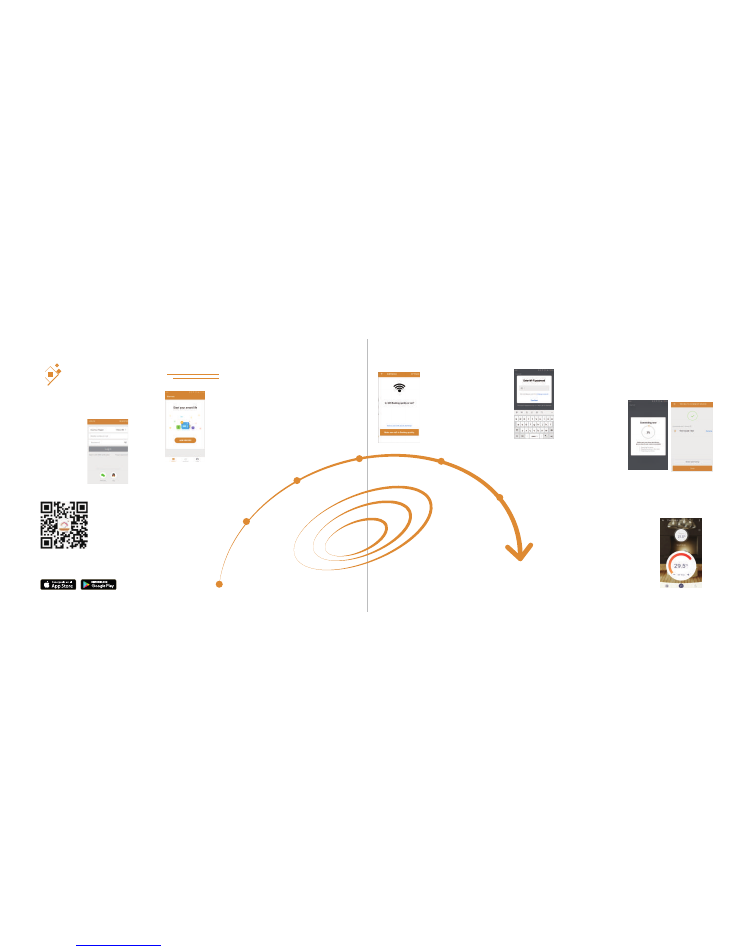
WIFI CONNECTIONION
Step 3: click “Add Device”on the bottom of the screen.
Step 5: Fill in the phone with the WiFi network password, click “next”.
Step 7: You can check the real-time temperature, adjust or set the temperature,
switch on/off or do other operations on the main interface.
Step 1: Scan the QR code through a browser or download APP
“Warmme” from the major application markets to install it.
Step 2: Open warmme, log in through the registered
phone number or authorization from a third-party APP
account(Facebook,..etc.).
Step 4: Check the thermostat WiFi flag is
fast flashing. if not,operate the thermostat
according to the APP tips until it flashes
quickly. Click the “WiFi flashing quickly”
button .
Step 6: Click “done” after warmme is connected to the
thermostat successfully, then finished the distribution.
03
04

Setting Key-lock can prevent children and others from switching thermostat parameters.
In normal timed power ’on’ mode, press for 3senconds to lock the thermostat and
again for 3 seconds to cancel.
Press to turn on/off
FUNCTION & USER OPERATION
On/Off
Temporarily override temperature
Set the Time
Key-lock
Note: When frost protection mode is active, the thermostat will maintain
the frost protection temperature when in power ‘off’ mode.
In normal timed power ‘on’ mode, press
△
or
▽
to change the current
period temperature setting. The thermostat will revert to the normal
programmed setting at the start of the next time period.
In normal timed power ‘on’ mode, Press and ‘Time’ will be displayed.
Press again to enter day set.
Press
△
or
▽
to set day.
Press to confirm and enter hour set.
Press
△
or
▽
to set hour.
Press to confirm and enter minute set.
Press
△
or
▽
to set minute.
Press
to confirm then press to revert to normal screen.
Note: The ET-81W updates the time automatically when first connected to internet.
05
06

Holiday mode
Hold mode
In holiday mode, the ET-81 will maintain frost protection temperature until the holiday time ends. In normal
timed power ‘on’ mode, press to enter setting.
Press
△
or
▽
to select holiday.
Press to enter holiday days set.
Press
△
or
▽
to set holiday days .
Press to confirm and return to the normal screen.
Note: In holiday mode,’HOLIDAY LEFT’ and the days remaining will show on display.
To cancel holiday mode ,you can set the holiday days to 0 or press twice.
The ET-61 will maintain the ‘hold temperature’ until the hold period ends.
In normal timed power ‘on’ mode, press to enter setting.
Press
△
or
▽
to select hold.
Press
to enter hold time set.
Note: In hold mode,’HOLD’ will show on display.
To cancel holiday mode ,you can set the holiday days to 0 or press twice.
Each day of the week has 4 time periods,you should allot a temperature to each time period. Set the
temperature above room ambient temperature and the heating will come on until the desired temperature
is reached, or, set the temperature low and the heating will not come on during that time period. The
default settings are shown in the table below.
Press
△
or
▽
to set hour.
Press
to enter minute set.
Press
△
or
▽
to set minute.
Press
to enter hold temperature set.
Press
△
or
▽
to set hold temperature.
Press
to confirm and return to the normal screen.
07
08
Period parameter table (initial value)
Mon----Fri
6:00 20℃
8:00 15℃
10:00 15℃
16:00 20.5℃
22:00 15℃
23:00 15℃
16:00 20.5℃
8:00 20.5℃
Sat----Sun
Week
Wake
Leave
Return
Sleep
ADVANCED SETTING
In normal timed power ‘on’ mode, press to enter setting.
Press
△
or
▽
to select edit.
Press to enter edit set.
Press
△
or
▽
to set hour.
Press to enter day selection.
Press
△
or
▽
to select the day to be set.
Press to enter period selection.
Press
△
or
▽
to select the period to be set.
Press to enter start time set.
Press
△
or
▽
to select start time hour.
Press to enter minute set.
Press
△
or
▽
to select start time minute.
Press to enter temperature set.
Press
△
or
▽
to select temperature.
Press to confirm and move on to next time period.
Caution: These are normally set by technicians during initial installation.
In normal timed power ‘on’ mode, press to enter setting.
Press
△
or
▽
to select setup.
Press to enter advanced setting.
Each parameter can be accessed by pressing and adjust the values as required.(the default values
are recommended and changing these may adversely affect the way the thermostat works.)
09
10
1
3
No.
Name
Default value
Ranges
Temp offset
Frost Protection
Floor sensor
Room sensor
0
℃
0
℃
ON
- 5
℃
-- 5
℃
- 5
℃
-- 5
℃
OFF/ON
Frost-preventive switch
4
5
6
7
8
9
10
5
℃
Both sensors
35
℃
℃
0 S
5
℃
--15
℃
Room temperature sensor
Floor temperature sensor
Both sensors
20
℃
-45
℃
℃
/
℉
0 S/30 S/60 S/90 S
0.5
℃
/1
℃
/2
℃
/3
℃
0%--100%
0W-3450W
Anti freezing temperature
Sensor select(Room,Floor)
Floor limit temp
Temperature unit
Delay output
Delay output
Backlight brightness
Power setting
Power rating
Power consumption
Factory reset
1
℃
80%
0W
——
——
Back
Yes/Back
TROUBLESHOOTING
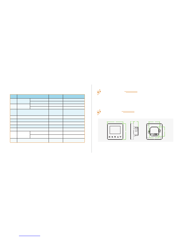
DIMENSION (MM)
Room sensor error = Built-in sensor short-circuit or disconnected.
Floor sensor error = Floor sensor short-circuit or disconnected.
Note: Should a sensor fault display, please connect us for assistance.
Fault Codes
PARAMETER
PARAMETER
11
12
86
86
16
26
59
51
51
mounted in a standard 86L×86W×35H(mm) wall box.
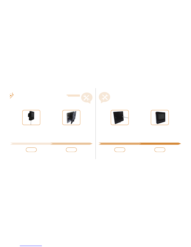
Installation
INSTALLATION AND WIRING INSTRUCTIONS
Replace front panel whilst ensuring
the pins engage properly in the
circuit board socket.
Fix the back section to wall box
with screws provided.
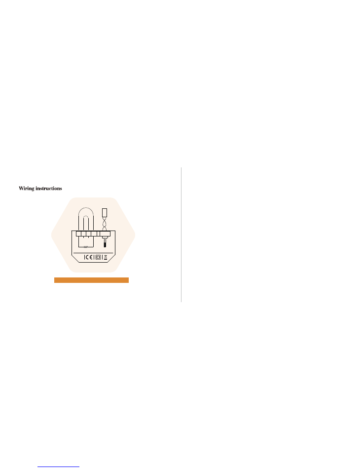
Wire the back section as shown in
the wiring diagram.
Loosen fixing screw on the base of
the thermostat and separate front
panel from back section.
13
14
Step 1
Step 2
Step 3
Step 4
The ET-81 series thermostat should be
NOTE:
Caution: Ensure power is disconnected when wiring!
15
MAX LOAD:
15A
SENSOR
L1
N1 N
L
SENSOR
POWER
85V-265V
50/60Hz
IP 21
Pow
er
Lo
ad