Full Text Searchable PDF User Manual
ALL IN ONE
Heat Pump Water Heater
INSTALLATION AND OPERATION INSTRUCTIONS
Please read this user’s manual carefully before operate the unit.

CONTENTS
A. IMPORTANT REMARKS
-----------------------------------------------------------------------------------------------
1
B. DESCRIPTION OF HEAT PUMP
----------------------------------------------------------------------------------
2-3
C. INSTALLATION INSTRUCTION
-----------------------------------------------------------------------------------
4-6
D. OPERATION PANEL INSTRUCTION
---------------------------------------------------------------------------
7-11
E. MAINTENANCE AND SERVICE
--------------------------------------------------------------------------------
12-14
F. UNIT CIRCUIT DIAGRAM
----------------------------------------------------------------------------------------
15-16
G. ANNEX LIST
-------------------------------------------------------------------------------------------------------------
17
WARNING:
1. This unit must be installed by the professional persons, dealers or special installation
companies authorized. Or otherwise, accidents maybe possibly caused and use effect maybe
possibly be affected.
2. Be sure that the unit is STOP operation when disconnecting the power supply to the
unit .Disconnect all electric power supplies before servicing.
3. This appliance is not intended for use by persons (including children) with reduced physical,
or lack of experience and knowledge, unless they have been given supervision or instruction
concerning use of the appliance by a person responsible for their safety.
4. Children should be supervised to ensure that they do not play with the appliance.
5. If the supply cord is damaged, it must be replaced by the manufacturer or its service agent or
a similarly qualified person in order to avoid a hazard.

1
A. Important remarks
Thank you for choosing our products. Before installation, it is strongly recommended to read
this instruction firstly. This manual includes the information of installation, debugging,
running and maintenance of the products.
Every unit of products has passed strictly test to ensure safety and high efficiency operation.
The manufacturer of this product will not be held responsible if someone is injured or the unit
is damaged, as a result of improper installation, debugging, and unnecessary maintenance
which is not in line with this manual.
The installer should be an authorized technician, and install the system follow the diagram
on the equipment.
Please notice the following information during installation:
1. Applied working temperature of heat pump: -7~43
℃
.
2. Check whether the power supply and wire meet the standard of the unit.
3. Do not alter the power wire or socket and the metal parts should be connected to GND well. Do
not change the GND connection of the system.
4. The appliance shall be installed in accordance with national wiring regulations.
5. When the system is connected to a fixed power supply, a 3mm space switch should be equipped.
At the same time, must connect a power leakage protector. (30mA, 0.1sec.)
6. When finish all the wiring, check it again before power on.
7. Do not install the system in the warehouse where flammable gas may leak out.
8. Do not insert hands or object into the vent of the heat pump, it may cause the dangerous to
people or damage the system.
9. To make the system more efficiency, please install the main unit at a place with good ventilation.
10. Do not put (or install) the operating panel at a wet place, do not cut and reconnect the
connecting wire.
11. Before turn on the system at a first time, ensure the water tank is full filled with water.
12. The inlet of the water tank equips with a filter (detachable), clean it according to the water quality
and running condition of the system (the period should be 2~3 months)
13. While the water supply has been stopped or the system stops running for a long period in winter,
should be drain the tank water to avoid water system frost crack.
14. The highest temperature of outing water is 60
℃
, when using, tune up to a suitable temperature
(the most suitable temperature for human is 38
~
45
℃
, if the temperature is higher than 55
℃
, it
may cause the danger of scald). Normally, the setting temperature can be from 10
℃
- 55
℃
, the
model with Auxiliary heater can reach up to 70
℃
.
15. Move the main unit at max. 30 degree angle. Do not drop down or upend the unit.
16. Maintain the system by an authorized technician. And disconnect all power when servicing.
17. The water quality requirements for the heat pump: Chloride content in the water should be
<250mg/L; the PH of the water range is 6.5~8.5; the Calcium carbonate saturation index in the
water range is 1.0~0.4. Warranty does not apply to the heat exchanger, electrical heater and
water tank if it s connected to water quality out of the range.
18. Please provide the warrantee card and S/N No. enclosed with the product for after service.
2
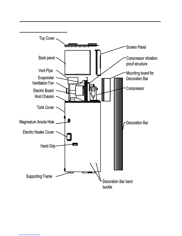
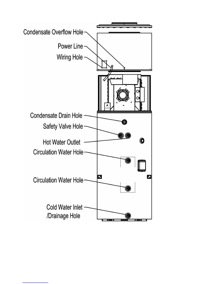
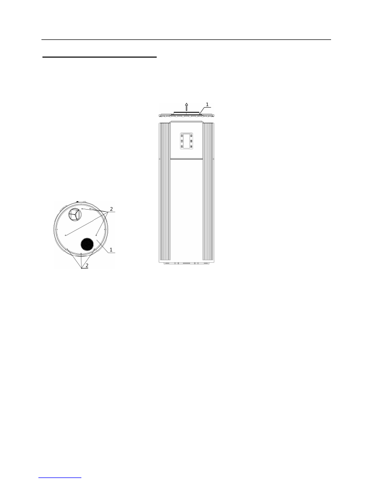
B. Description of heat pump
Unit constructions (outside):
3
Remark:
1. The above drawing is for reference to identify the name of each part. Details are subject to real unit.
2. The drawing of “Electric Heater hole” is only for the unit with Auxiliary heater models; other models
without auxiliary heater function are not available.
3. There are two “Circulation Water Hole” for optional connection. It can be available when the user
requests an external connection for hot water circulation. Normal models are without these holes.
4
C. Installation instruction
Note:
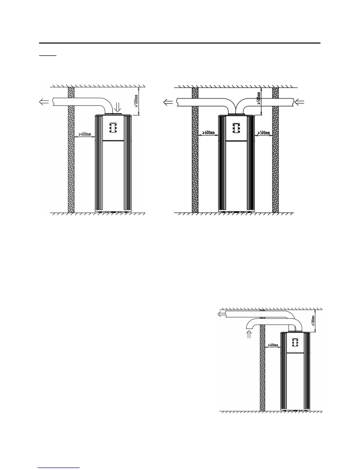
1. This heat pump unit can be installed at veranda, hallway or other place where is easy to install and
stable. The air inlet & outlet are at the top side, main unit should not be placed at an open air. Avoid the
rain or debris to enter the vents. The air inlet and outlet can connect the
φ
150mm air duct. As below,
(Fig.1)
(Fig.2)
2. When install as Fig.1, only connect the air inlet or outlet, the unit should be installed at a place of
ventilation, and the side connected with water pipes should has enough space. Then, if the unit is
installed besides the room, it can be connected the air outlet duct to the room for exchange fresh air
and cooling function; If the unit is installed in the room, it can be pulled out room’s air for ventilation
function.
3. If install as Fig. 2, the unit can be installed by the
middle of the wall, and connect the air inlet and
outlet pipe for air exchange. The distance of the unit and wall or other obstacle should not be too short.
Keep a certain distance.
4. If install as Fig. 3, the unit is installed outside the room, the air inlet and outlet is connected indoor for
air exchange (and cooling). In this way, the indoor air inlet and
outlet should have a distance
≥
2m to avoid mix air.
5. Because the air outlet comes with cooling air, the surface of
the pipe may have condensation water, it’s necessary to
insulate the indoor outlet pipe to prevent water leakage.
6. Heat pump water heater unit must be placed upright, and
installed on a solid place where can be able to withstand the
weight over 700kgs. Supporting surface should be evenness
(obliquity less than
2°)
7. When install the unit, there should has some measures of
sound insulation and shockproof in order not to affect
neighbors.
(Fig. 3)

5
C. Installation instruction
8. When unit operation, put the unit in a well-ventilated place and non-blocking the air vent, so that the
machine can be able to inhale and exhaust enough air, to achieve hot water supply function.
9. There should be with drain around the system unit for drainage. And the surrounding should have
enough space for maintenance. Because the top cover can be opened, at the top side of the unit
should have
≥
800mm space for maintain.
10. Nearby the system unit, there should be reserved a water supply pipe and hot water pipe interface
equipped with valves, the water inlet pipe should be with filter (for cleaning).
11. For waterway connection of this integrated unit, please refer to the following (Fig.4) “Waterway
installation diagram”. On the system unit, there should be installed Three-port valve, Safety valve and
Filter. Connect them to the water inlet and outlet of the unit.
12. If the Heat pump equip with
“Circulation Water Hole”
(optional), It can be connected with SOLAR
WATER HEATER, HEAT RECOVERY SYSTEM and other water heating equipment to heat the water
tank by circulation. Retain original if no need external connection.
13. The working pressure of this water heater tank must
≤
0.7MPa. Water inlet must connect the safety
valve, and its operation pressure is 0.7MPa, Connect another end of the safety valve to water supply
pipe. The safety valve should be connected by a small rubber pipe interlinked with atmosphere; this
pipe must not be blocked, in order to drain the water when the tank’s pressure exceeds 0.7MPa.
14. Water inlet pressure should >0. 1MPa, if the pressure is lower, can connect the pressure pump on
inlet pipe to get the high water flow.
15. Ensure the water tank is full fill with water before turn on the system: First, open the valve on the
water supply inlet, then switch on either valve of the water outlet, and then you can affuse water to the
tank until the water overflow the water outlet valve. After which you can turn off the water outlet valve
and check for leakage. Make sure there is no water leaking.
NOTE: For the first time use, ensure the water tank has been filled with water before turn on the
system.
16. In order to ensure the water tank filled with water, require a certain section of hot water outlet side
should be about 10cm higher than the water heater tank section.
17. The water heater temperature thermal sensor was put and sealed well in a tank by the factory before
launch to market. No need to install it when installation.
18. This water heater unit is filled with refrigerant by the factory, and no need to vacuumize or refill
refrigerant.
19. In the winter cold regions, the water heater unit can not turn off the power, if the system stops running
for a long period in winter, should be drain the tank water to avoid water pipe or tank frost crack.
Meanwhile, we should strengthen or check the external pipe to prevent the pipe frozen.

6
C. Installation instruction
Installation diagram:
(Fig.4)
Remark:
1. For the first time use, ensure the water tank have been filled with water before power on to prevent
burn out.
2. Follow with the water heater unit, there are some installation parts (see the annex detail list of parts).
As for other water system components, the user or installation company should provide by themselves.
3. Before installation, it’s better to reserve a water supply pipe interface, hot water outlet pipe interface
and drainage pipe interface. Among them, the water supply pipe and hot water outlet pipe should be
used in line with standards for drinking water pipes. (E.g. PPR pipe or stainless steel pipe, etc.), can
not use iron pipe or the rubber hose with odor for installation.
4. If the using place below 0
℃
, make sure to insulate the water pipes to prevent frozen.
5. Air inlet /outlet can connect the vent tube, but pipe should not be too long and less crankle.
7
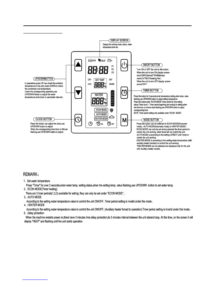
D. Operation panel instruction
1. Panel - Operation:
8
D. Operation panel instruction
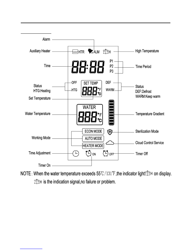
2. Panel - Display:
Cloud icon flashing during the connect with the internet,always lighting after connected with the
internet,no lighting means no cloud control function.
9
D. Operation panel instruction
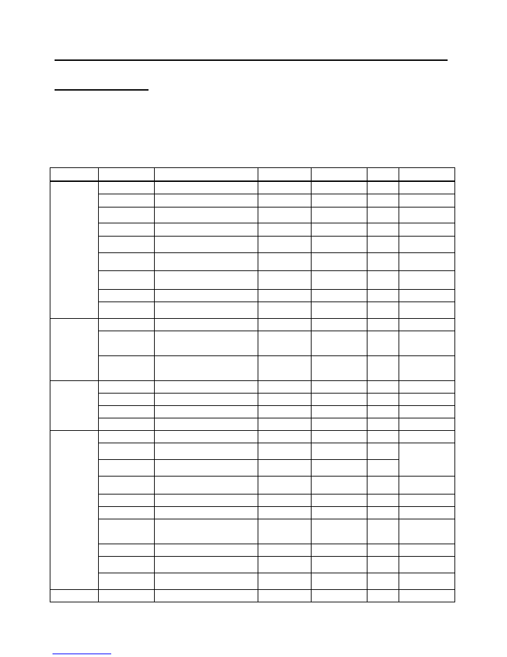
3. Parameter Setting:
Press “MODE” button for 5 seconds; enter the Parameter setting status, the main parameter code as
below sheet:
Type
Code
Parameter Name
Setting Range
Factory Setting
Unit
Remark
Temperature
Control
F11
Setting temperature
5-70
55
C
F12
Difference in Temp.
1 - 30
5
C
F13
Determine Heat pump stop
ambient temp.
-10 – 5
-7
C
F14
Highest temp. for heat pump
40 – 60
55
C
F15
Turn on or off electric
heater mode
0 - 1
1
-
F16
Ambient temp. for start electric
heating
-10 - 20
0
C
F17
Turn on or off electric heater
for sterilization function
0-1
1
F18
Sterilization cycle
1-990
336
hour
F19
Water thermal sensor
temp. amendment
-5 – 5
0
C
Compressor
F21
Compressor start delay
0 – 10
3
minute
F28
Econ mode turn on or off
electric heater
0 - 1
1
F29
Heat pumps working or not in
heater mode
0 - 1
1
Defrost
F31
Defrost start temp.
-20 – 20
-2
C
F32
Defrost finish temp.
0 – 50
25
C
F33
Defrost start time
1 – 999
30
minute
F34
Max. defrost time
Off, 1 – 99
5
minute
Alarm
F50
Low pressure alarm mode
0 - 2
2
-
F51
Auto resume times of low
pressure alarm
0 – 10
3
time
F52
Reset time of external alarm
auto resume times
0 – 999
60
minute
F54
Electric heater overheat
protection
0 - 2
2
-
F55
Overheat resume time
0-10
3
-
F56
Alarm resume time
0-999
60
C
F57
Exhaust temp. protection
mode
0 – 2
1
-
F58
Exhaust protect temp.
50 – 125
110
C
F59
Exhaust temp. protection
Return difference
1 – 30
10
C
F60
Condensate drain hole
blocked alarm
0-2
1
Function
F61
Memory status when power off
Yes/No
Yes
-
10
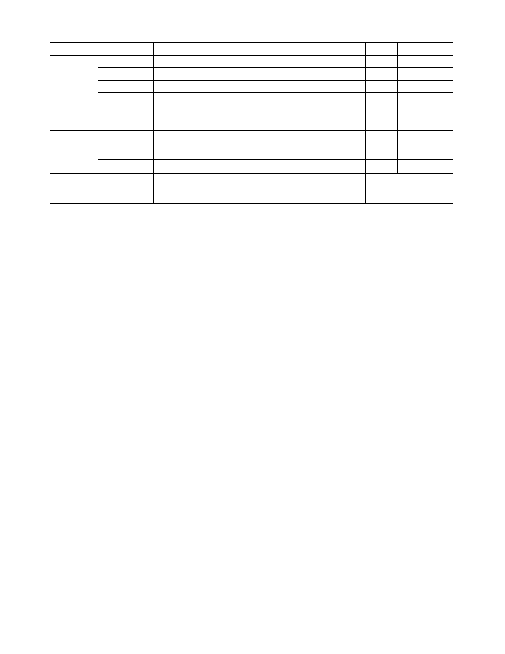
Remark:
When enter Parameter setting status, press “up” or “down” to choose parameter code; after choose one, press “Timer”
button to show this code’s setting value, and press “up” or “down” can set the value; After finish setting, press “Timer”
button to confirm and return to Parameter code status.
Setting
F69
Communication baud
24/48
24
-
Electronic
expansion
valve(EEV)
F70
EEV opening query
0–480
--
F71
EEV control mode
0–2
0
F72
Manually set EEV opening
100–480
350
F73
Set EEV superheat degree
-15–15
5
F74
Set EEV discharge temp
85–110
92
F79
Return gas temp.
--
System
Setting
F80
Password
OFF
0001 -- 9999
4321
-
“OFF” means no
password.
Set “0000” to
clear password.
F85
Display sterilization total time
-
-
hour
Testing
F98
Force defrosting (refrigeration)
Control panel
display “AdF”
Start compressor, 4-way
valve and fan motor. Press
any key to exit or 20 minutes
it will exit automatic.
11
4. Error Handling:
ERROR
CODE
ERROR STATUS
REASONS
ERROR HANDLING
A1
Thermal sensor
alarm
Water temp. sensor open
circuit or short circuit.
1. Check the water temp. sensor
connection.
2. Change the water temp. sensor.
A2
Condenser coil
sensor alarm
Condenser coil temp.sensor
open circuit or short circuit.
1. Check the condenser coil temp.
sensor connection.
2. Change the coil sensor.
A3
Exhaust sensor
alarm
Exhaust temp. sensor open
circuit or short circuit.
1. Check the exhaust temp. sensor
connection.
2. Change the exhaust temp. sensor.
A4
Ambient temp.
sensor alarm
Ambient temp. sensor open
circuit or short circuit.
1. Check the Ambient temp. sensor
connection.
2. Change the ambient temp. sensor.
A5
Low /High pressure
alarm
1.1. High pressure protection
switch off.
1.2. Ambient temp. too high or
water heat exchanger dirty
block.
2.1. Low pressure protection
switch off.
2.2. Leakage of refrigerant.
1.1Check
or
change
the
high
pressure protector.
1.2. Check if the surround temp. is
too high, or clean the heat
exchanger of water tank.
2.1. Check or change the low
pressure protector.
2.2. Supply refrigerant and check if
there is any leakage.
A6
(Auxiliary) electric
heater protection
overheat alarm
1. Electric heater protection
switch off.
2. Tank water temp. too high.
1. Check if the water temp. is as LCD
display, or if water temp. is too
high.
2. Change the Electric heater.
A7
Exhaust temperature
too high
1. Lack of refrigerant.
2. Mix with air in system.
3. Lack of lubricating oil.
1. Supply refrigerant.
2.
Re-vacuumizing,
and
fill
in
refrigerant.
3. Change the lubricating oil of
compressor.
A8
Condensate drain
hole blocked
1.condensate pipe blocked
;
2.Machine drain hole blocked
;
1.Check condensate pipe is blocked
or not.
2.Check machine drain hole is
blocked or not.
A9
Return gas temp.
sensor alarm
Return gas temp. sensor open
circuit or short circuit.
1.Check the Return gas temp.
sensor connection.
2. Change the ambient temp. sensor.
- -
Screen no display or
display insufficiency
1. No plug in power.
2. Mainboard and operation
panel communication break
off.
1. Check the power line and voltage.
2. Reconnect the line of
mainboard and operation panel.
3.
Change
the
mainboard
or
operation panel.
NOTE:
1. When the unit has error, the buzzer of the operation panel will make an alarm sound, and there will
show “Alarm” on the screen panel.
2. “ERROR CODE” will show on temperature display location by alternately.
3. Part of the error alarm can be automatically restored (resumed). That is the appeared alarm can be
eliminated by electronically controlled self-test.
4. Some of the error alarm is caused by large fluctuation of the external power, by this, just power off and
restart the unit to clear the error.
5. When the machine has error alarm and restart still can not eliminated error, please contact the after
service as soon as possible for solution.

12
E. Maintenance and service
Examination before trial run
1. Check the water tank is filled with water, and open the water outlet tap till water flow out.
2. Check the water pressure is normal (0.15Mpa~0.7Mpa).
3. Check the air inlet or outlet is well connected; and the air outlet pipe heat insulation is completed.
4. Check the power supply voltage is normal, whether according with the nameplate requirement.
(Range ± 10%).
5. Check whether the equipped parts are screwed /locked well.
6. Check whether the wirings are according with the Circuit diagram, and the earth-wire is
connected.
7. Check whether the wind inlet and outlet has been cleaned up and no obstacle.
8. Check whether the condensate drain pipe is connected well and no blockage.
9. After power-ON, check the control panel display is normal.
Trial running
1. After the machine starts, to hear and determine whether there is abnormal sound or collision
during operation, if there is abnormal sound, stop the unit immediately and check for it until there
is no abnormal sound to continue operation.
2. For the first time power on, the compressor will have 3 minutes delay protection function.
3. Observe whether the drainage of condensate water is smooth, prevent the chassis stagnant or
spill water.
4. For the first time discharge hot water or start the units after a long time closure, the water tap of
outlet pipe may flow muddy water, this is a normal phenomenon, and continue to drain for a period
of time can be cleared.
5. After stop operation for a long time, there may have condensation water hereabout the air outlet or
pipe (especial in humidity weather), this is a normal phenomenon, use a dry washcloth to clean it
or by air dry.
6. The advance setting parameters of the operation panel has been set at the factory, users no need
to reset it, the maintenance person should be carefully set if needed.
Maintenance and service
1. After carry and move the unit by the first time installation, and connects the water pipes and filled
the tank with water. The machine should be rest for 1-2 hours before start trial running.
2. The water heater inlet filter needs to be cleaned once per 3 months. At the same time, per half
year we suggest draining all the storage water and repeatedly wash for 2-3 times to remove the
dirt and sediment.
3. To keep the unit in good heating performance, suggest cleaning the Air inlet /outlet filter net per
month, or using high pressure air tube to clean the Heat exchanger. Be careful not to damage the
copper tube.
4. Clean the Electric Heater per 6 months. (When clean the Electric Heater or Heat Exchanger must
cut off power supply.)
5. Change the Anode (Magnesium rod) per 6 months for better anticorrosion and antiscale.
According to different water quality, change the Anode rod when it’s expended.
6. When clean the Tank, Electric Heater, Heat Exchanger or Anode rod must cut off power supply.
7. If the supply cord is damaged, it must be replaced by the manufacturer or its service agent or a
similarly qualified person.
8. Special statement: for what does not in accordance with the requirements of above maintenance
and service work lead to the failure problem, does not apply to our warranty scope.
13
E. Maintenance and service
Heat Pump main unit disassembly
If want to check and maintain the top main parts of the unit,should disassembly the decoration
panel,back panel and top cover of the unit,follow the below steps(Fig.5,6)to process.
(Fig.5)
(Fig.6)
Top cover disassemble
Remove all the item-2 screws of the top cover-1,push up the top cover vertically by 15 to
20mm.Separate the top cover with the host,then you can have a preliminary review of the main
system and do maintenance.(View Fig.5,Fig.6)
14
(Fig.7)
(Fig.8)
(Fig.9)
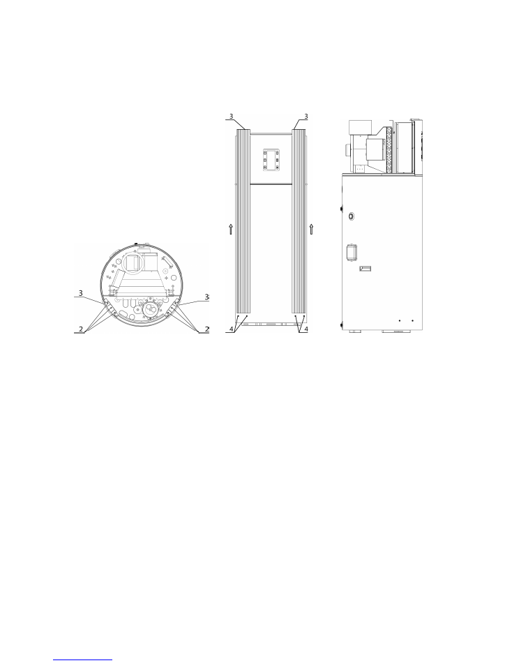
Disassembly outside cover
1) When power off and disassemble the top cover,remove the decoration panel-3 by remove the
screws-2.Push up the decoration panel-3vertically by 150-200mm until it separate from the hang
buckle-4.(View Fig.7,Fig.8)
2) Loose the power wire from the terminal block,to avoid the wire get stuck when move up the top
shell.
3) Remove all the screws(item-2) from the Back panel(item-5),two sides decoration bar(item-6)and
tank shell(item-7).(View Fig.9)
4) At last,lift up the back panel(item-5)slightly can finish the disassembly.(View Fig.9)
5) After maintenance,make sure the air outlet of shell should be aimed at the fan outlet pearl cotton
when reinstall the shell.
15
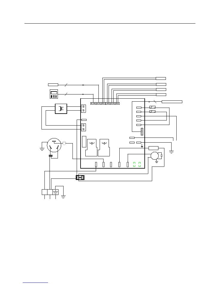
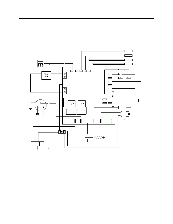
F. Unit circuit diagram
The following is a unit circuit diagram (for user’s reference); the unit practical connection should be as the
circuit /wiring diagram on the machine.
1). Heat pump
without
auxiliary electric heater:
2
1
Comp
Fan
Valve
Elect
R
S
C
开/关
时钟
定时
模式
BLACK/
12V
RED/
220V
5
COMPRESSOR
LOW
HI
B
X
S
N
LOW-PRESURE PROTECTOR
HI-PRESURE PROTECTOR
RETURN GAS TEMP. SENSOR
EXHAUST TEMP.SENSOR
COIL TEMP.SENSOR
AMBIENT TEMP.SENSOR
Electronic expansion valve
YELLOW/GREEN
FAN MOTOR
4-WAY VALVE
OPERATION PANEL
WATER TEMP.SENSOR
Transformer
YELLOW/GREEN
POWER SUPPLY
L
2
3
N
L
16
F. Unit circuit diagram
2). Heat pump WITH auxiliary electric heater:
BLACK/
12V
模式
定时
时钟
开/关
C
S
R
Elect Valve Fan
Comp
1
2
L N
3
2
L
POWER SUPPLY
YELLOW/GREEN
Transformer
WATER TEMP.SENSOR
OPERATION PANEL
ELECTRIC.HEATER
YELLOW/GREEN
4-WAY VALVE
FAN MOTOR
YELLOW/GREEN
ELECTRIC HEATER PROTECTOR
PRESURE PROTECTOR
Electronic expansion valve
AMBIENT TEMP.SENSOR
COIL TEMP.SENSOR
EXHAUST TEMP.SENSOR
RETURN GAS TEMP. SENSOR
N
B
X
S
HI
LOW
COMPRESSOR
5
RED/
220V
17
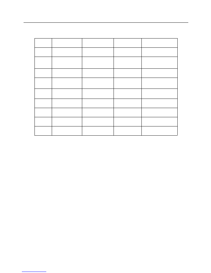
G. Annex list
ITEM
NAME
SPECIFICATION
QUANTITY
REMARK
1
Safety valve
1
2
Manual
1