Full Text Searchable PDF User Manual
1
L N
O
pe
n
C
lo
se
C
om
Power
supply
240V
Motor
Courtesy
lamp
Ground
+ 1
2V
C
om
ne
g t
x F
T
C
F
T
C
T
D
C
om
T
B
C
om
TD
TB
Réflex photocell
Zone 240V
Safety zone, isolated low voltage
Motor
M
oto
r E
ar
th
M
ain
s E
ar
th
M
ain
s L
iv
e
M
ain
s N
eu
tra
l
Date
Code Number:
Series
Model number
Draft
TVLink RS868
25/11/13
TVPRP868F08E
1- GENERAL DESCRIPTION
Electronic for the remote control of tubular motors for roller blinds, rolling shutters, doors with limit
switch inside or outside the motor, radio receiver section with transmitter channel memorization by
means of internal push button or via radio.
Possibility to connect wired with auto-test control before every closing movement.
Possibility to connect a 240 V
courtesy lamp with variable time from 1 min. to 12 hours (default
1min.)
Plastic housing for external use equipped with clamps.
Possibility of centralized controls for simultaneous control of several appliances.
Possibility to connect external mechanical controls with dynamic push button function and blockage
push button.
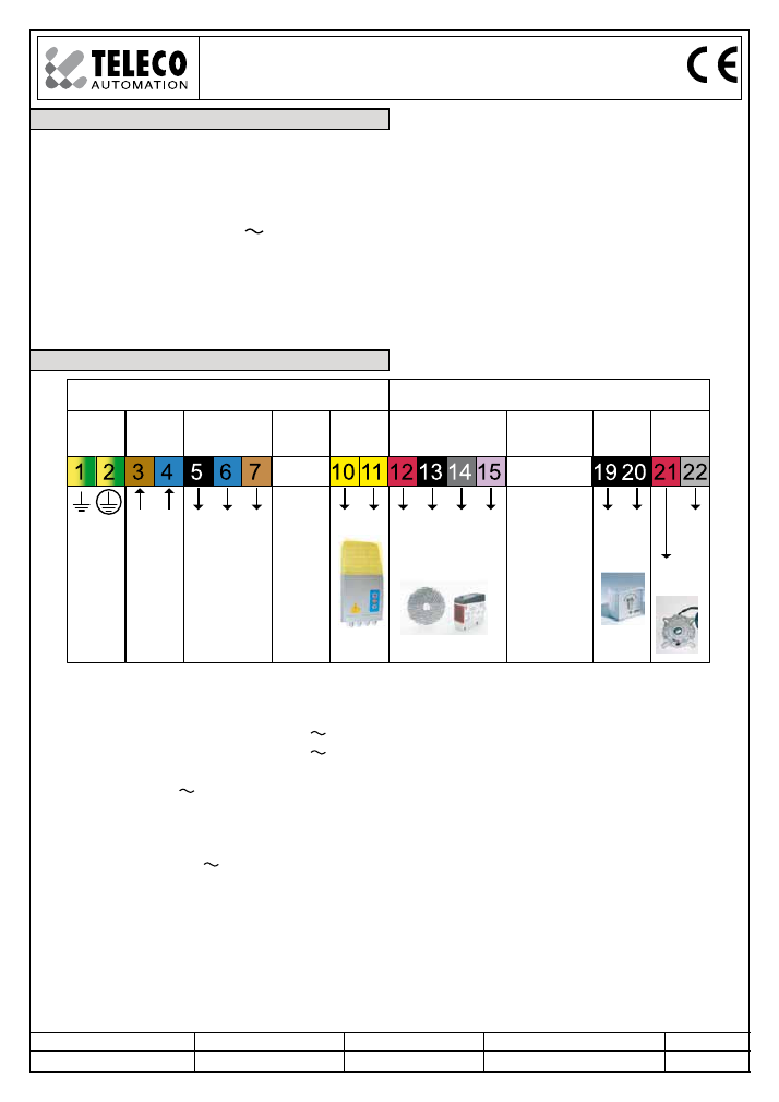
2- CONNECTIONS
Description of the connections:
1
Input ground general power supply
2
Input ground motor
3
Input general power supply 240 V phase
4
Input general power supply 240 V neutral
5
Opening output relay motor contact
6
Output 240 V neutral by means of fuse
(common motor)
7
Closing output relay motor contact
10-11 Output LC 240 V 300 W max. for
courtesy lamp
(only for the version with courtesy light)
12
Positive output 12/15Vdc 80mA
for photocells
13
Safety common contact
14
Negative output for photocells (autotest)
15
FTC input (NC normally closed)
19
Push buttons common for TD
20
Dynamic push-button input (NO normally open)
21
Stop push-button TB (NC normally closed)
22
Push buttons common for TB
24
Antenna ground
25
Antenna pole (wire 8.5cm)
T574.01
TELECO AUTOMATION SRL - Via dell’Artigianato, 16 - 31014 Colle Umberto (TV) ITALY
TELEPHONE: ++39.0438.388511 FAX: ++39.0438.388536
www.telecoautomation.com
This document is the property of Teleco Automation Srl who reserves all reproduction and copying rights
2
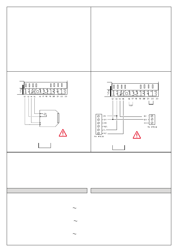
Connections with photocells
if the FTC input are
not used put a bridge
between 14 and 15
terminals
14
15
Warning: The installed safety device must
ensure the safety of the door
according to EN13241-1 (EN12453,
EN12445)
If TB stop NC contact is not used it must be
jumpered.
If the FTC input NC is not used it must be
jumpered to 14 terminal
TB
3- Technical specifications
Reception frequency
868.3 MHz
Sensibility (finely tuned signal) 1 uV
Power supply
240 V
Operating temperature range
-20° – +50°C
Maximum power at the motor:
Voltage
250 V
Maximum power
400 W
Maximum commutable power
at output courtesy lamp
240 V 300 W
Antenna
The correct installation and connection of the
antenna is fundamental in order to obtain a good
action ray for the installation.
Connect the provided 8.5 cm piece of wire to the
antenna pole connection on the device.
As an alternative (and for better results) use a
tuned antenna connected to the receiver via
coaxial cable RG58 (impedance 50ohm) with a
maximum length of 15 metres (mod. ANT868)
8,2Kohm
resistance
R
E
F
LE
X
+
-
com
nc
Connections with reflex
if the FTC input are
not used put a bridge
between 14 and 15
terminals
14
15
12/15 Vdc
3
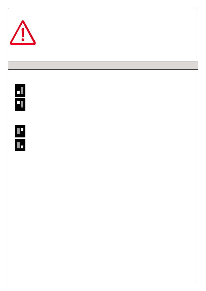
4- Dip-switch function
After the reset, the control unit carries out only opening commands until the
door is fully opened.
After the complete opening, the functioning of the commands is standard.
1 2
ON
1 2
ON
1 2
ON
Dip1:
OFF
The closing movement is in dead man mode, during the opening it is automatic
(even if the automatic reclosing is excluded)
ON
The opening and closing movement is automatic.
Dip2:
ON
Activation of automatic reclosing **
OFF
Deactivation of automatic reclosing
1 2
ON
**The automatic reclosing is activated only if the door is fully open to the limit switch.
After passing the photocell the door closes (after 3 sec.).
4
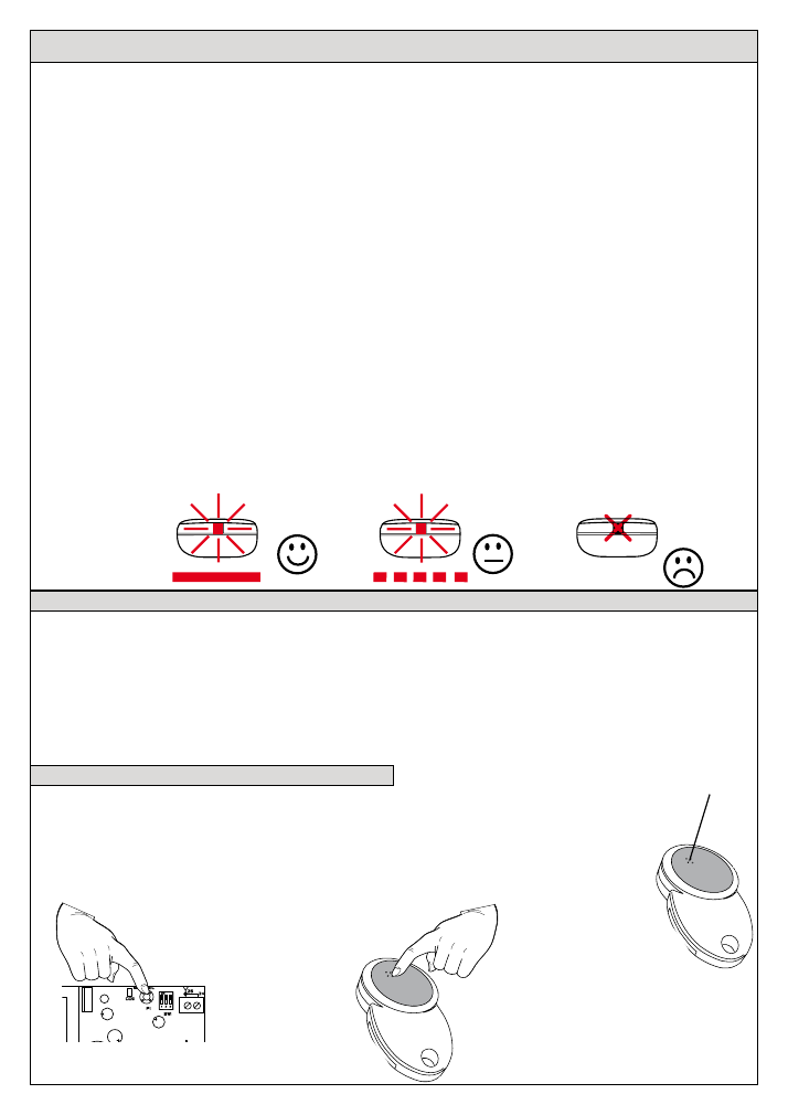
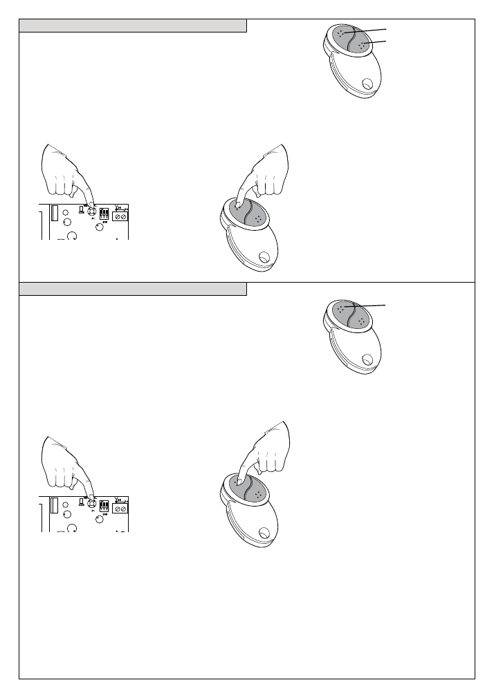
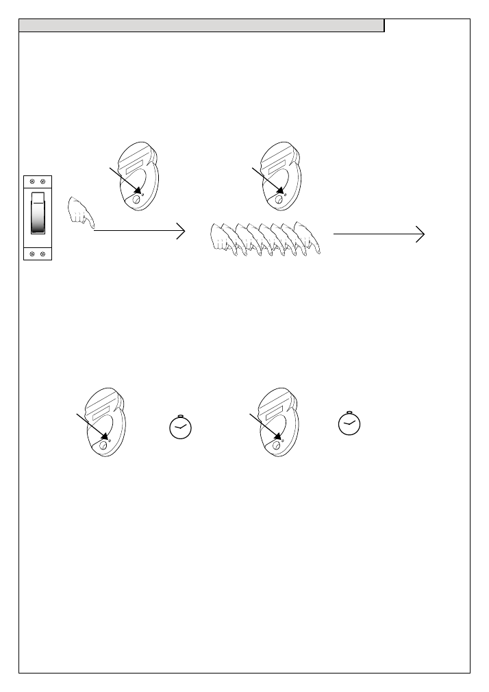
5.0- To memorize the transmitters from the receiver
5.1.1- Mode 1: single push-button
The memorization of the channels is carried out in single mode for each channel;
the memorised channel will activate the controls in dynamic mode open, stop, close.
open,
stop,
close
Press and hold
the push button P1,
the buzzer B1 will make 1 beep and
sound continuously.
Beep ... Beeeeeep
Transmit the channel which is to be
memorized, the buzzer B1 will sound
intermittently.
Beep Beep Beep Beep
Transmitters
The transmitters are encoded in the factory and each transmitter has its own unique code.
Caution! If you keep a channel button pressed down for more than 30 seconds the transmitter will
automatically turn off.
The receiver is compatible with all transmitters of the TVLink range: TVTXV, TVTXP, TVTXE, TVTXC,
TVTXI, TVTXK, TVTXQ, TVTXL, TVTXS.
The transmitter code can be inserted (memorized) or deleted directly in the receiver or via radio from
the transmitter. This last possibility allows to insert new transmitters into an existing installation, with-
out acting directly on the receiver. This may be carried out easily by the end user without the help of
the installer, and guaranteeing the total secrecy of the code.
- The codes transmission type is “Rolling- code”. The code is changed for every transmission through
the use of an algorithm that only the receiver is able to recognize and therefore to decide if the trans-
mitted code corresponds to the original code.
- In the receiver the user code is memorized under Eeprom, which maintains the code information
even when faced with blackouts (max. 42 code-memorizations).
It is adjustable to delete the whole memory before each installation.
Errors during the memorizing
If the code is not memorized it could be due to the following conditions:
-The code already exists in memory
-The memory is full (max. 42 codes). In this case the Buzzer will make 3 beeps both during the
memorization phase both after the reset of the receiver.
5.1- Possibility to memorize the transmitter in three ways:
1 -
Mode 1
: Single channels with dynamic function, open, stop, close
2 -
Mode 2
: Control from two channels ch1 with ch2, ch3 with ch4 and ch5 with ch6 and ch7.
Ch1, ch3, ch5 for opening controls, ch2, ch4 and ch7 for closing controls, ch6 stop.
3-
Mode 3
: the memorised channel operates on the courtesy light in on/off mode.
Battery OK
LOW Battery
CHANGE the
Battery
Transmitter
le behaviour
according to
battery status:
5
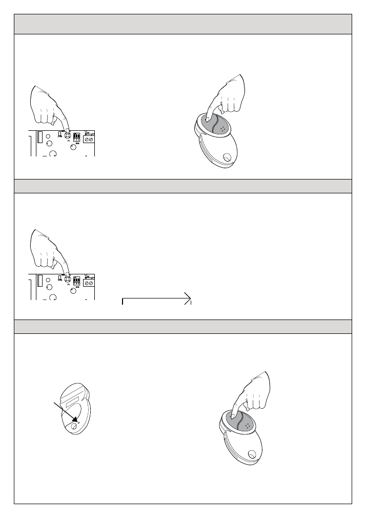
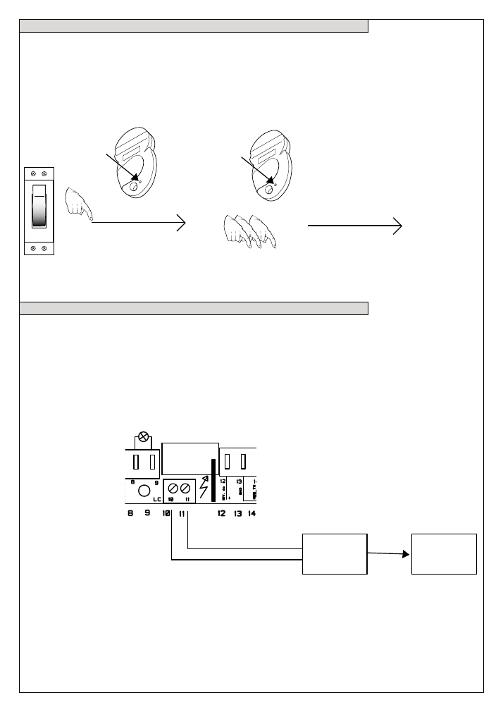
5.1.3- Mode 3
The memorization of the channels is carried out in single mode
for each channel; the memorised channel will turn on and turn
off the courtesy light in dynamic mode.
Press
three times and hold
the
push button P1 down, the buzzer
B1 will make three beeps and sound
continuously.
Beep Beep Beep ... Beeeeeep
Transmit the channel which is to be
memorized, the buzzer B1 will sound
intermittently.
Beep Beep Beep Beep
On/Off light
5.1.2- Mode 2:
The memorization of the channels is done in pairs:
channel 1 with channel 2 (or vice versa) and
channel 3 with channel 4 (and vice versa) and channels 5-6-7.
open
Press
twice and hold
the push button
P1 down, the buzzer B1 will make two
beeps and sound continuously.
Beep Beep ... Beeeeeep
Transmit one of the channel which is to
be memorized, the buzzer B1 will sound
intermittently.
Beep Beep Beep Beep
close
press 3 times
and hold
press 2 times
and hold
6
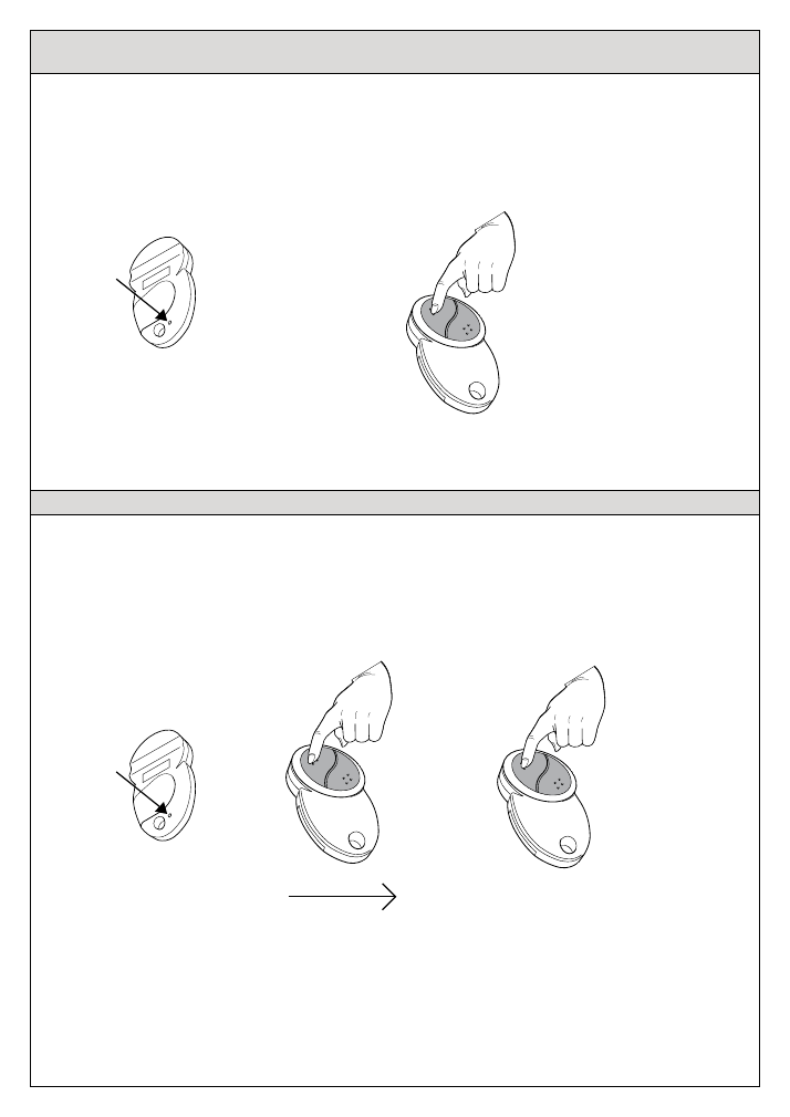
5.2.1- To cancel a code from the receiver: the deletion in single mode or in pairs is done as in
the memorization mode 1, 2 and 3:
Press
4 times and hold
the push-
button P1 down, the buzzer B1 will
emit an intermittent slowly sound.
Beep Beep Beep Beep ... . ...Beep... . ...Beep... . ...Beep
Transmit the code which is to be
cancelled, once the channel is cancelled
the buzzer B1 will sound continuously.
Beeeeeep
press 4 times
and hold
5.2.2- To cancel all memorized codes:
Press
5 times and hold
the push-button P1 down for
at least 10 s
(during this period the
buzzer B1 will sound intermittently and quickly) until the buzzer B1 will sound continuously. At
the end release the push-button.
Beep Beep Beep Beep Beep ... Beep...Beep...Beep ... ... Beeeeeep
press 5 times
and hold
5.2.3- To cancel via radio a code by means of a transmitter already set in the memory:
P3
press for three
times
Press the internal push button P3
at regular intervals for
three times
within 5 s, the buzzer B1 will emit an
intermittent slowly sound.
Transmit the code which is to be
cancelled within 5 s. Once the channel
has been cancelled the buzzer will stop
sounding.
Beeeeep ... Beep... . ...Beep... . ...Beep
10 sec.
Beeeeeep
7
5.3- How to insert a transmitter via radio without accessing the receiver when the memory is
empty (first installation), in this mode the channels function of the transmitter will be in mode 2.
P3
press once
Press the internal push-button P3 of the
transmitter, the receiver will be activated
for the memorization and the buzzer will
sound continuously for 5 s.
Transmit the channel which is to be
memorized within 5 s. Once the channel
is memorized the buzzer will sound
intermittently.
The transmitter to be inserted will become the master transmitter for inserting other transmitters.
Warning: when the memory is empty do not give power to more than one receiver at the same time,
because the above mentioned procedure activates all receivers.
Beeeeeep
Beep...Beep...Beep...Beep...
5.4- Memorization of channels from the transmitter (additional transmitters)
P3
press once
1- Press the button P3 of
the transmitter, the buzzer
will sound continuously.
2- Press within 5 seconds a channel
which is already present in the memory
of the receiver, the buzzer will interrupt
the sound for 1 sec, and then carry on
for 5 seconds.
The type of memorization of the channels (single or in pairs) depends on how the channel, which is
used in point 2, has been memorized.
Beeeeeep
3- Transmit the channel to be
memorized. Once memorized
the buzzer will sound
intermittently, release the push
button.
Beeeeeep
Beep...Beep...Beep...Beep...
1 sec.
memorized
transmitter
memorized
transmitter
new
transmitter
8
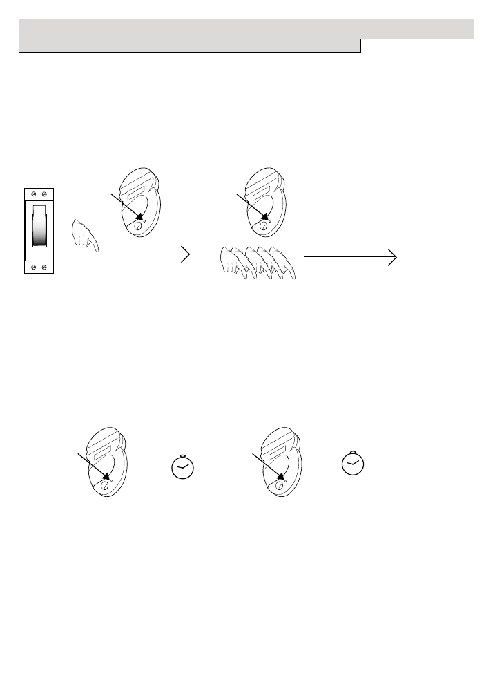
6.1- Procedure for the courtesy light time setting (from 1min max 12h)
This procedure can be done within 30 seconds after the reset.
Sum 1min to the set time.
P3
press and
hold for 5
sec.
3- After the desired time press
again the push button P3 of the
transmitter in order to exit and
memorise the courtesy light time,
the light turns off.
1- Press for 5 sec. the
push button P3 of the
transmitter; the buzzer will
sound 1 beep,
release and re-press within 5 sec. the
push button P3 of the transmitter 5
times, the buzzer will sound 1 beep
at each pressure and at the end it will
sound 3 beeps
P3
press 5 times
(if after 5 sec. the push
button P3 will not be
pressed the buzzer will
sound 4 beeps and exit
from the procedure).
2- Press the push button P3
of the transmitter, the buzzer
will sound one beep and the
courtesy light turns on, the
time to be memorised starts.
P3
press once
Beep
P3
press
once
start time count
Stop and memorize
the time
Beep Beep Beep
1
2
3
Beep Beep Beep Beep Beep
Beep
5 sec.
wait 5 sec.
1 2 3 4 5
6.0- Time settings
240V
Beeep
On
9
6.2- Procedure for the automatic re-closing time setting (from 5s max 90s) (default 5sec.)
This procedure can be done within 30 seconds after the reset.
Sum 5s to the set time.
P3
press and
hold for 5 sec.
3- After the desired time press again the
push button P3 of the transmitter in order to
exit and memorise the re-closing time.
The buzzer will sound one beep.
1- Press for 5 sec. the push
button P3 of the transmitter;
the buzzer will sound 1 beep,
release and re-press within 5 sec. the
push button P3 of the transmitter 8 times,
the buzzer will sound 1 beep at each
pressure and at the end it will sound 2
beeps
P3
press 8 times
Beep Beep
1
2
(if after 5 sec. the push but-
ton P3 will not be pressed
the buzzer will sound 4
beeps and exit from the pro-
cedure).
2- Press the push button P3
of the transmitter, the buzzer
will sound one beep, the time
to be memorised starts.
P3
press once
Beep
P3
press
once
Beep
start time count
Stop and memorize
the time
Beep Beep Beep Beep Beep Beep Beep Beep
Beep
5 sec.
wait 5 sec.
1 2 3 4 5 6 7 8
240V
Beeep
On
10
7.0- Courtesy light operation mode as the ambient light or alarm
This procedure can be done within 30 seconds after the reset.
P3
press and
hold for 5 sec.
1- Press for 5 sec. the push
button P3 of the transmitter;
the buzzer will sound 1 beep,
release and re-press within 5 sec. the
push button P3 of the transmitter 3
times, the buzzer will sound 1 beep
at each pressure and at the end it will
P3
press 3 times
sound:
3 beeps to indicate ambient
light mode and
5 beeps to indicate alarm
function.
3 Beeps: ambient light
5 Beeps: alarm function
Beep Beep Beep
Beep
5 sec.
wait 5 sec.
1 2 3
240V
Beeep
On
7.1- Courtesy light function as alarm
It is possible to use the output of the courtesy light, to interface the control unit to an alarm system,
memorizing a radio alarm transmitter (code: TVSSH or TVTCTM) with mode 3 memorization and acti-
vating the “courtesy light as alarm” function (see 7.1 ).
If the control unit receives an alarm signal from the radio alarm transmitter, the courtesy light output is
activated for 1 minute.
Warning:
the courtesy light output provides 240Vac. The interface of the alarm system must be ar-
ranged according to the specifications of the installed alarm system.
Alarm
interface
Alarm
system
11
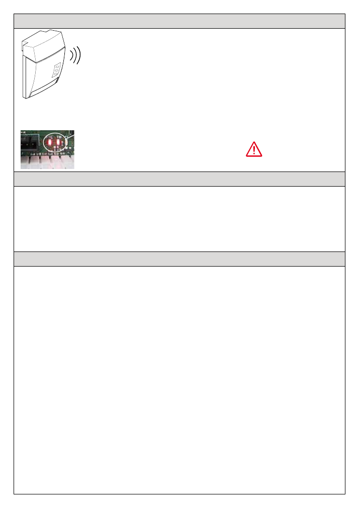
8.0- Acoustic signals emitted by the control unit
1 beep: reset
2 beeps: motor is not connected
3 beeps: error on FTC input (FTC is activated)
5 beeps: error on safeties test (safeties test failed)
8 beeps: Limit switch error
It is possible to close the door also with a not working CSP or with a negative safety
test (forced closing), by pressing and holding down the closing push button; after 5 s
the control unit closes in dead man mode.
Beep ...
TB Led and FTC Led:
ON: TB and FTC input alarm not activated,
the inputs work normally.
OFF: input alarm activated, security alarmed
The LED switches off every time that the autotest is done.
OK
9.0- Safety inputs function
-TB: Normally closed input, stop-push-button stops the movement in each condition. (It is not possible
the forced closing)
- Traditional photocell input (inputs 12-13-14-15); if not used jumper the inputs 14-15 (it only works in
closure).
WARNING: all the devices invert the movement for 2 sec.
If the safety is broken it is possible to close the door with a maintained closing command; press the
command for >5sec.; after this time the movement is in dead man mode.
WARNING
The above mentioned product must be installed only by qualified technical personnel in
compliance with the standards of automatic openings. All connections must be rated for a
single-phase power supply of 240V. For the disconnection from the power line, use an all-
pole switch with contact with an opening of at least 3,5mm. Only suitable materials for the
connections must be used to guarantee insulation that complies with current standards on the
subject of electrical safety. The programmer carries out movement controls; all the necessary
safety devices are to be seen separately.
Incorrect wiring will cause incorrect functioning impairing the safety purpose for which the
product has been designed so that people injuries could occur; failure to follow instructions
can cause personal injury and/or property damage.
The correct working of the product must be checked once a year.
Keep the 240V wires from the low voltage safety wires separately. The earth-wires must be fixed
by means of an additional fastening nearby the terminals; this fastening has to be done by qualified
technical personnel during the installation phase.
The appliance has been tested with a power supply wire type H05VV-F; the power supply wires for
outdoor use have not to be lighter than the ordinary wires type H05RN-F. The safety devices have to
be in conformity with EN12978. The installation of the control unit has to be done by fixing the box
vertically with the clamps downwards.
The programmer is in conformity with the RAEE and RoHS directive.
The earth wire must be longer than the other wires because it must be the last to break off if
the cable clamps are slack.
Remember that there are specific standards that must be complied with both as regarding
the safety of the electrical systems and as regarding the remote control of tubular motors for
roller blind.
In the view of a constant development of their products, the manufacturer reserves the right for
changing technical data and features without prior notice.
12
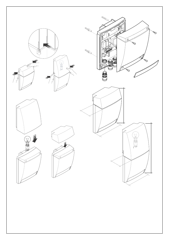
BOX DIMENSIONS
ASSEMBLY
DISASSEMBLY
EXPLOSION VIEW
85 mm
145 mm
205 mm
85 mm
145 mm
290 mm
www.telecoautomation.com