Full Text Searchable PDF User Manual
Operating instructions
Pressure switch, model PS01-W1
Pressure switch, model PS01-W1

2
Switzer operating instructions pressure switch, model PS01-W1.
O
I-P
S
0
1
-W
1
1
1
/2
0
1
6
© 11/2016 Switzer Process Instruments Pvt. Ltd.,
All rights reserved.
Prior to starting any work, read the operating instructions!
Keep for later use!
Contents
1.
General information
3
2.
Installation and guidelines
4
3.
Electrical connection
5
4.
Operation
6
5.
Procedure
7
6.
Maintenance
10
7.
Mounting dimensions
11
Contents

3
Switzer operating instructions pressure switch, model PS01-W1.
O
I-P
S
0
1
-W
1
1
1
/2
0
1
6
1. General information
PS01-W1
Pressure switch is a simple electro mechanical device operating on
basic principles of Levers and opposing forces.Three essential elements, various
combinations of which form the basics for presenting hundreds of variants to suit a
variety of industrial applications are :
1. Sensing element which can be either of sealed piston or diaphragm
(metallic or
elastomer)
2. Spring, to determine the range setpoint
3. Snap-acting microswitch, available in a wide variety.
General
The instrument is manufactured, checked and supplied in accordance with our
published specification. When installed and used in normal or prescribed applications
with the lid in place and within the parameters set for mechanical / electrical
performance, will not cause danger or hazard to life or limb.
Storage
■
Storage temperature -10°C to +60°C.
Safety warnings
■
Opening or dismantling when pressure switch is live with respect to electrical or
pressure will result in a hazard.
■
Pressure switch must be selected and installed by suitably trained and qualified
persons in accordance with appropriate codes of practice to avoid failure resulting in
injury or damage due to misuse or misapplication.
Note:
The instrument is calibrated within the claimed accuracy with precision and skill.
Therefore tampering or adjustment of striker screw or any other component where there
is red paint seal will lead to malfunctioning.

4
Switzer operating instructions pressure switch, model PS01-W1.
O
I-P
S
0
1
-W
1
1
1
/2
0
1
6
Handling prior to fi tting
-
Check the instrument connection thread size to avoid mismatch with pressure port.
Mounting / Connection / Precaution
1. Position gaskets / O ring correctly while the covers are fixed. Cover mounting
screws must be tight.
2. Properly seal the electrical entries and cables with correct weatherproof cable
gland.
3. Do not exceed stated maximum working pressure & maximum temperature. The
sensing element will be permanently damaged if the applied pressure exceeds the
maximum working pressure.
4. Connected electrical load should not exceed stated maximum electrical capacity
in both ampere and voltage.
5. Do not establish pressure connection by rotating the housing. Hold the hexagon of
the sensor with suitable spanner and tighten.
6. Flush the pipe system before fitting. Ensure that no stress is produced on the
sensor process connection and are sealed without leak.
7. Mount the instrument firmly and rigidly either directly on the pressure pipe line
or on a vibration free wall, panel or pipe barrier. The instruments are for vertical
mounting. Any tilt may lead to set point shift.
8. If process temperature is higher than the
following permissible maximum
temperature
it can be brought down by using longer pressure (impulse) piping.
Permissible ambient temperature
■
-10°C ... +60°C
Permissible medium temperature
■
-20°C ... +110°C for SS and Buna-N
■
-20°C ... +95°C for Neoprene
■
-20°C ... +130°C for EPDM
■
-20°C ... +200°C for Silicone
9. For steam application use condenser coil or a syphon
10. For air application, use proper filters (dust collectors) to ensure that the process
line is not clogged with accumulation of dust / foreign particles.
11. Ensure that suitable dampener / snubber is used in rapidly fluctuating pressure
input.
12. Necessary fasteners and mounting bracket are provided with the instrument for
panel / wall / 2“ pipe mounting option. Following items are provided
For panel / wall mounting : 2 screws
For 2“ pipe mounting
: U bolt, nut, washeres and mounting bracket
2. Installation guidelines
5
Switzer operating instructions pressure switch, model PS01-W1.
O
I-P
S
0
1
-W
1
1
1
/2
0
1
6
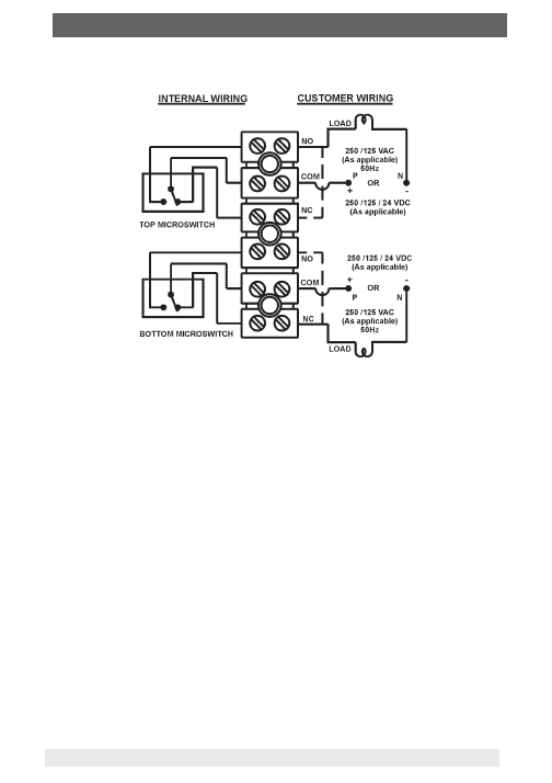
3. Electrical connection
The terminal blocks are suitable for 2.5 Sq.mm wires.
Fig.1

6
Switzer operating instructions pressure switch, model PS01-W1.
O
I-P
S
0
1
-W
1
1
1
/2
0
1
6
4. Operation
Process pressure when applied to the sensing element creates a force which
overcomes the force of a pre-tensioned spring and in turn moves a balancing arm to
eff ect a minimal movement to actuate the microswitch.
Contacts gets reset when the force of the sensing element becomes less than that of
the spring load.
The instrument reset point can be varied by adjusting the diff erential spring in low
ranges (available as option).
7
Switzer operating instructions pressure switch, model PS01-W1.
O
I-P
S
0
1
-W
1
1
1
/2
0
1
6
5. Procedure
Fixed on-off diff erential models
a) Rotate the range adjustment screw clockwise to increase the switching point.
Rotating anti-clockwise will decrease the switching point.
b) After setting, r
e-fi x the locking device back in position to prevent unauthorised
adjustment of the setpoint.
c) The center screw and the striker screw are precisely adjusted and factory-set
using thread lock sealant. Alteration of centre screw height will disturb the contact
established between the sensor and the balance beam. Disturbance of striker screw
will result in microswitch not acting properly or result in setpoint shift.
Sensing of switching points
Fix the instrument on to a calibrator setup with a master gauge of accuracy better than
1% to set the actuation point.
Setpoint should be preferably in the mid of the adjustable range span.
Adjustable on-off diff erential models
On-off diff erential value can be adjusted for a wider value from about 10 to 15% of the
FSR to a maximum of 60% as specifi ed against each range. The minimum value will
vary with diff erent switch combinations. This adjustment is achieved by an auxiliary
spring brought into action when the switch actuating plate moves up before it operates
the microswitch. Adjustment of the load of the spring decides the pressure diff erence
between the on point and off point.
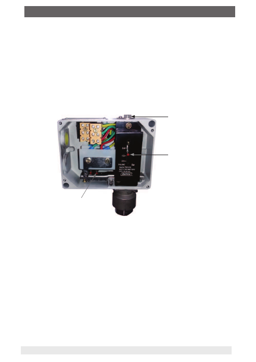
Range screw
Range scale Index
Striker screw
Fig.2
8
Switzer operating instructions pressure switch, model PS01-W1.
O
I-P
S
0
1
-W
1
1
1
/2
0
1
6
Procedure Contd.,
a) In adjustable diff erential model set the lower switching point fi rst. Release the aux.
spring to be free by lifting up the nyloc nut and the Diffl
. Adjuster. Using the range
adjuster set the lower switching point. Then load the aux. spring by turning in the
Diffl
. Adjuster clockwise to set the upper switching point.
b) Adjusting the diff erential adjuster will shift only the upper switching point i.e. the
switching pressure diff erence (on-off diff erential) alone changes. A clockwise
rotation will increase upper switching point and anti-clockwise rotation will
decrease it.
c) The upper switching point should not exceed the maximum range value.
d) After setting the diff erential, tighten the Nyloc nut to lock the diff erential adjuster to
prevent loosening during operation.
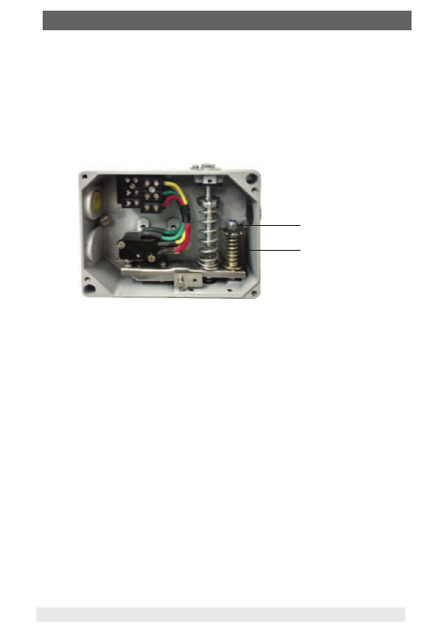
Adjustable on-off diff erential models
On-off diff erential value can be adjusted for a wider value from about 10 to 15% of the
FSR to a maximum of 60% as specifi ed against each range. The minimum value will
vary with diff erent switch combinations. This adjustment is achieved by an auxiliary
spring brought into action when the switch actuating plate moves up before it operates
the microswitch. Adjustment of the load of the spring decides the pressure diff erence
between the on point and off point.
Nyloc nut
Diff erential adjuster
9
Switzer operating instructions pressure switch, model PS01-W1.
O
I-P
S
0
1
-W
1
1
1
/2
0
1
6
Procedure Contd.,
Notes
1) In the instruments with 2 SPDT switches for DPDT action, the synchronization of
actuation is achieved within practical limits.The switches are synchronized as per
customer preference either on falling or on rising pressure. If no preference is
indicated, synchronization is done on fall in pressure at factory.
2) ON & OFF set point should not exceed the upper or lower range of scale value
3) Ensure that impulse pipework applies no stress on sensing element housing and use
spanners to hold pressure port/ housing when connections are made.
4) Use the instrument only f
or the medium specifi ed.
e)
Precaution:
The switch actuating screw on the balancing arm is critically
adjusted. Disturbance of this would result in malfunctioning while on-off diff erential
adjustments are made. If accidentally disturbed, to reset microswitch adjust the
striker screw height such that the balancing arm is not in contact with auxillary
spring seat during switch de-actuation thereby ensuring that the auxillary spring
remains unloaded during de-actuation. Refer Fig.3.
For actuation of the microswitch, the balance beam has to lift the aux. spring seat
which is pre-loaded with the desired value of wide band On -Point. Ref Fig.4
Fig.3 : Switch at ‘off’ position Aux
spring load not acting
Fig.4 : Switch at ‘on’ position Aux
spring load acting
0.5/0.8 mm gap
Aux. spring
Aux. Spring seat
Microswitch
Microswitch
Aux. spring seat
Aux. spring

10
Switzer operating instructions pressure switch, model PS01-W1.
O
I-P
S
0
1
-W
1
1
1
/2
0
1
6
Maintenance
Inspections should be carried out at quarterly to yearly intervals depending upon
operating conditions.
Isolate instrument from process and power before removing lid. Check terminals
for tightness.Check that cable tails are not fouled or chafed. Check for internal
condensation and rectify.
It is recommended that the instruments are checked for calibration/operation once a
year. However, in critical applications, microswitch is to be operated and checked more
frequently to ensure correct functioning.
Process lines are to be periodically checked for accumulation of dust / foreign particles
to avoid clogging. Clogging would render the instrument non-functioning as the sensing
element shall not have free movement during pressure fluctuations.
In the case of diaphragm operated instruments, do not attempt dismantling the sensing
diaphragm as it would permanently disturb the factory settings. Special jigs are needed
for reassembly and hence replacement is not recommended at the user end. However,
cleaning of the diaphragm chamber can be performed by flushing with a cleaning fluid,
which is compatible with the diaphragm and its housing material.
Vent or Drain periodically.
6. Maintenance
11
Switzer operating instructions pressure switch, model PS01-W1.
O
I-P
S
0
1
-W
1
1
1
/2
0
1
6
Switzer Process Instruments Pvt. Ltd.
128 SIDCO North Phase, Ambattur Estates,
Chennai 600 050
Tel. +91 44 2625 2017 / 2018 / 4991 / 4324
sales@switzerprocess.co.in
www.switzerprocess.co.in
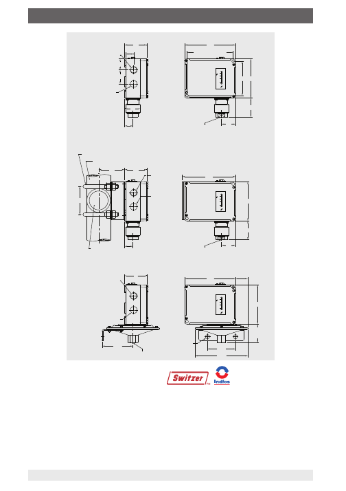
7. Mounting dimensions
130
118 x 88 Diagonal
mounting pitch
88
100
47 ... 80
±2
35
28
36
20
1/2" NPTF
cable ent ry
Optional
21
Ø38
57
130
100
Alu.=48
SS=40
±2
57
78.5
Ø135
71.5
fixing holes
2 Nos. 10.5Ø
±2
136
100
47 ... 80
±2
35
Cable ent ry
21
57
(fix `U' clamp vertically)
horizontal position
2" pipe optional
71.5
68
`U' bolt 2 No s.
3/8" B SW
customer
2" pipe by
1/4" NPTF
32.5
1/2" NPTF
1/2" NPTF
cable ent ry
Optional
1/4" NPTF
1/4" NPTF
1/2" NPTF
cable ent ry
Optional
Cable ent ry
1/2" NPTF
Cable ent ry
1/2" NPTF
High range direct or panel mouning
High range 2" pipe mouning
Low range surface mouning