Full Text Searchable PDF User Manual
April 2002
Sperre Industri AS
Tel +47 70 16 11 00
Fax +47 70 16 11 10
E-mail:industri@sperre.com
Sperre Rotterdam BV
Tel +31 180 463 299
Fax +31 180 463 264
E-mail:rotterdam@sperre.com
Sperre Asia PTE LTD
Tel +65 763 63 00
Fax +65 763 18 11
E-mail:asia@sperre.com
Sole suppliers of
genuine spare parts
GB
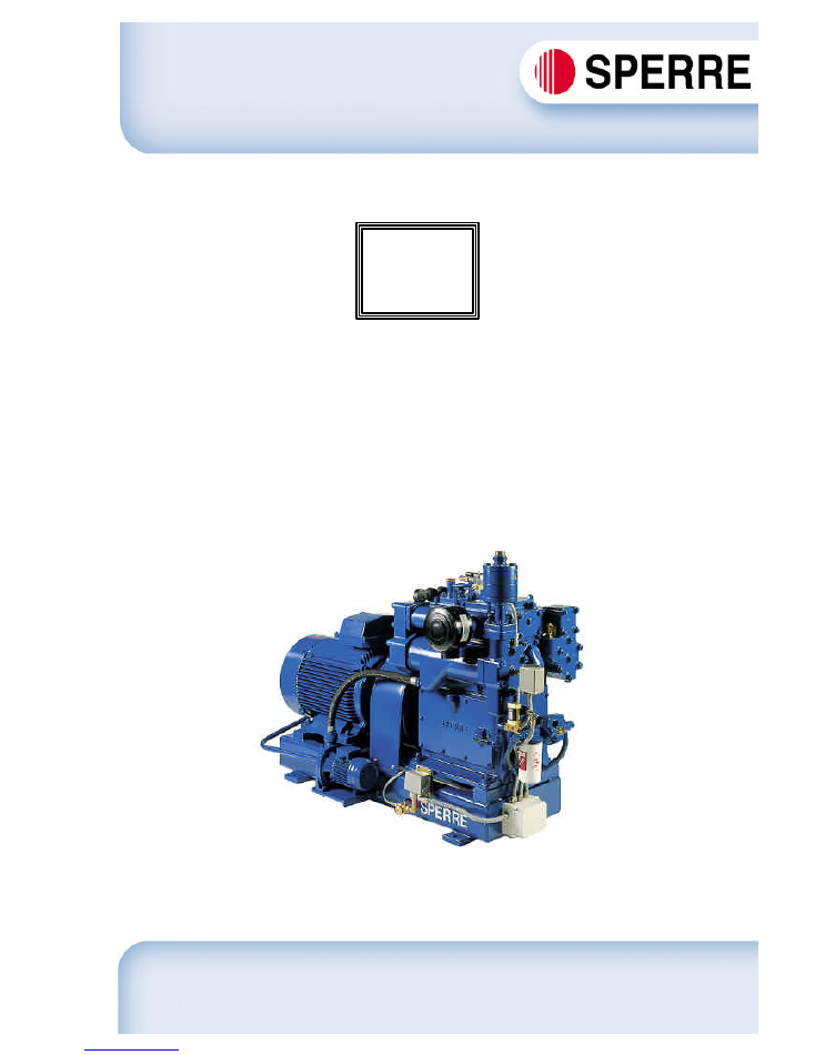
INSTRUCTION MANUAL
AIR COMPRESSOR
HV2/210
Water-cooled

Instruction manual for Water-cooled Air Compressor HV2/210 - 1 -
GB
INTRODUCTION
The purpose of this handbook is to describe the design and function of the compressor and to provide
basic instructions for inspection and maintenance of the equipment.
To ensure proper installation, operation and maintenance from the very beginning, it is essential that the
operator should read this handbook with care and attention.
The maintenance intervals and certain technical details given in this handbook ate mean values based on
experience. These values may vary depending upon the operating conditions of the individual
compressor.
The manufacturer disclaims liability for damage due to unskilled operation or improper maintenance of
the equipment.
Keep the compressor in good mechanical order, and remember that proper preventive maintenance of
the equipment will reduce the risk of damage and unnecessary shutdowns.
The manufacturer reserves the right to amend technical specifications without prior notice.
ELLINGSØY, April 2002
SPERRE INDUSTRI A/S
CONTENTS
Page
1. ORDERING REPLACEMENT PARTS ......................................... 2
2. DESCRIPTION OF COMPRESSOR............................................ 2
2.1. Design .................................................................................. 2
2.2. Safety equipment.................................................................. 3
3. INSTALLATION AND OPERATION ............................................. 3
3.1. Installation instructions ......................................................... 3
3.2. Cooling water system ........................................................... 3
3.3. Starting up ............................................................................ 4
3.4. Operation.............................................................................. 4
3.5. Stopping................................................................................ 4
4. FAULT TRACING ......................................................................... 5
5. INSPECTION AND MAINTENANCE............................................ 6
5.1. Maintenance schedule.......................................................... 6
5.2. Valves ................................................................................... 7
5.3. Lubricating oil system ........................................................... 8
5.4. Bearings ............................................................................... 8
5.5. Piston and piston rings ......................................................... 9
5.6. Flexible coupling................................................................... 9
5.7. Coolers ................................................................................. 10
5.8. Filters.................................................................................... 10
6. TECHNICAL DATA....................................................................... 11-12
7. REPLACEMENT PARTS LIST ..................................................... 13-14
8. ILLUSTRATIONS ......................................................................... 15-18
9. ILLUSTRATIONS FOR REPLACEMENT PARTS LIST ............... 19-20

Instruction manual for Water-cooled Air Compressor HV2/210 - 2 -
1. ORDERING REPLACEMENT PARTS
A list of replacement parts and drawings of the various components will be found at the end of this handbook.
The following information must be given when ordering spares.
A. COMPRESSOR TYPE
B. COMPRESSOR SERIAL NUMBER
C. PART NUMBER AND DESCRIPTION
D. QUANTITY ORDERED
E. RATED WORKING PRESSURE OF COMPRESSOR
The type designation (A) and serial number (B) are shown on the rating plate which is fixed to the crankcase.
The rating plate is shown in Fig. 1.
Pleace note that the manufactorer does not supply oversize or undersize parts, or unmachined parts for further
machining and fitting.
The manufactorer disclames all liability for damage due to the use of non-genuine replacement parts.
Order for replacement parts should be sent to:
Adress:
SPERRE INDUSTRI AS
E-mail:
industri@sperre.com
6057 ELLINGSØY
Web adress : http://www.sperre.com
NORWAY
Phone:
+ 47 70 16 11 00
Fax
+ 47 70 16 11 10
2. DESCRIPTION OF COMPRESSOR
2.1 Design
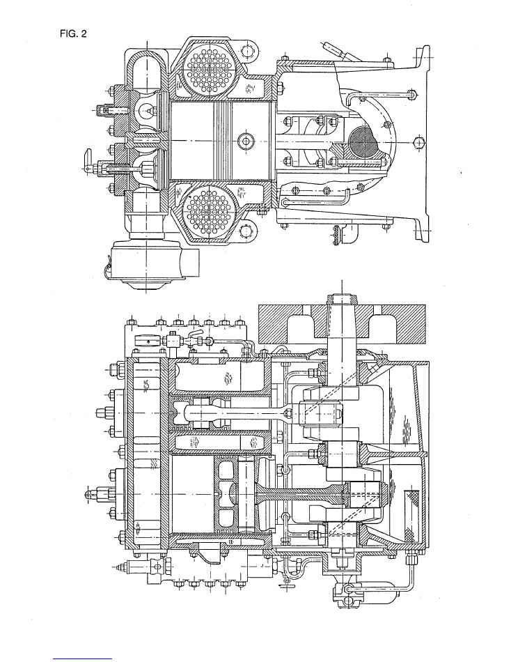
The machine coverded by this instruction book is a single cylinder, 2-stage single-acting watercooled air
compressor. The design principle is shown in the cross-sectional drawing Fig. 2.
The first stage of the compressor is the low-pressure stage (LP) and the second is the high-pressure stage (HP).
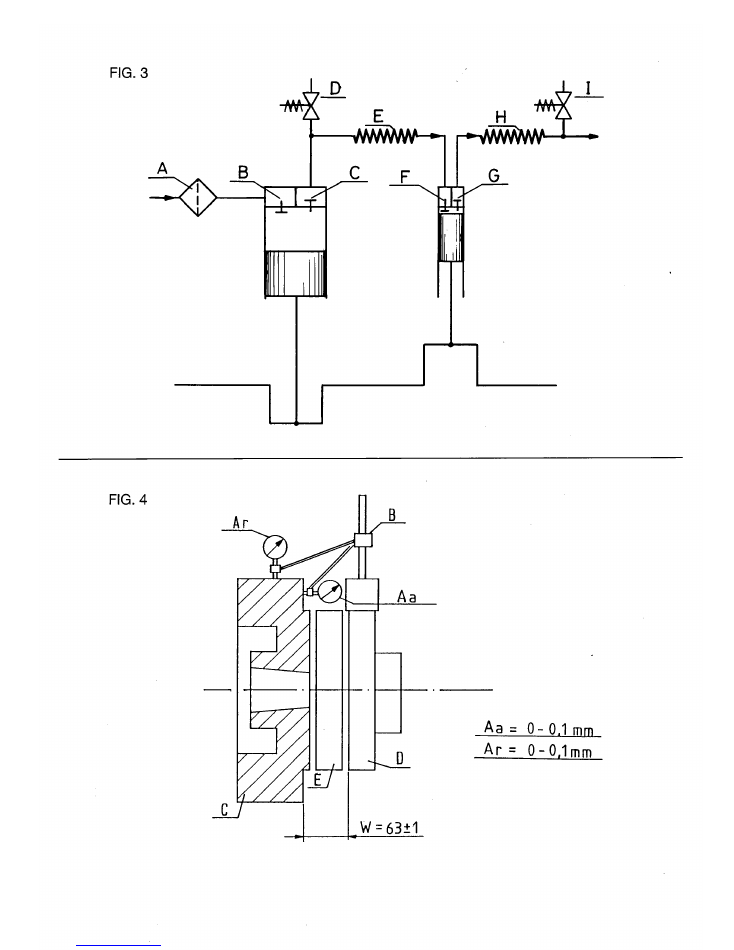
Air circulation through the compressor is shown in Fig. 3. The letters indicate:
A. Suction filter
B. LP suction valve
C. LP delivery valve
D. LP safety valve
E. LP cooler
F. HP suction valve
G. HP delivery valve
H. HP cooler
I. HP safety valve
All bearings are pressure lubricated by a gear pump fitted to the end of the crankshaft.
Two replaceable tube-type coolers are fitted in the compressor cylinder block. The first serves to cool the air after
first-stage compression, the second provides cooling after second-stage compression. The cooling water intake
and outlet are located so that the water circulates through the cylinder block and ensures efficient cooling of the
air and compressor cylinder walls.
The compressor compresses air from atmospheric pressure to rated pressure, with an upper limit of 35 bars.
The compressor is designed for installation together with an electric motor or other drive unit on a well-stiffended
base, with a flexible coupling between compressor and motor.
Every compressor is tested before delivery from the factory, and all compressor sets supplied with motor are
aligned before dispatch. See chapters 3.1. and 5.6.
This compressor is designed to supply compressed air for engine starting, and for the operation of air power
equipment and instruments. It complies with the requirements specified by the classification institutions.

Instruction manual for Water-cooled Air Compressor HV2/210 - 3 -
2.2. Safety equipment
The compressor is fitted with two safety valves, one after the first-stage compression and the other after second-
stage compression.
The safety valves, which are set at the factory in accordance with the working pressure specified by the
customer, ensure that the pressure does not exceed the limit for which the compressor and the compressed air
system are dimensioned.
The cylinder block cooling jacket is fitted with a safety plate which will be blow out if the cooling water is
subjected to excessive pressure. Use only manufacturer's genuine safety plates to replace blown plates.
A pressure switch is generally included in the automatic control system. This serves to stop the compressor if the
lube oil pressure falls belowe a predetermined minimum.
3. INSTALLATION AND OPERATION
3.1. Installation instructions
Every compressor unit is supplied complete with drawings and specifications showing its dimensions and
attachment points. The customer also receives installation instructions giving recommendations for the
installation of equipment and piping.
The compressor unit should be installed in a location where the air is not excessively warm. Warm intake air
reduces the capacity of the compressor. Normally, the ambient temperature for electrical equipment should not
exceed 45
o
C. The compressor unit bedplate should lie plane to its foundation. After the unit is installed, check
the alignment of compressor and motor. The procedure is shown in Fig.4.
Use vernier callipers or inside micrometer callipers to check the distance (W) (Fig.4). This should be the same
around the whole circumference of the coupling.
Using a micrometer (A), check the radial misalignment between the coupling halves as shown in Fig.4. The
maximum micrometer reading (A) should be as illustrated in Fig. 4.
Even if the unit has been installed on vibration dampers, an alignment check is to be recommended after
installation.
Piping should be so installed that there is no risk of water pockets.
Other equipment should not be installed around the compressor unit in such a way that inspection and
maintenance operations may be hampered.
3.2. Cooling water systems
It is of the greatest importance to the operation and life of the compressor that a good and reliable supply of
cooling water is ensured. The quantities of cooling water required are given in Table T.1. These specifications
apply to both seawater and freshwater cooling.
Whether the compressor is connected to a central cooling system or has its own separate cooling water pump, it
is important to ensure that the cooling water is circulating properly. In this connection it is not sufficient simply to
check that the compressor pressure gauge is registering cooling water pressure.
If the cooling water feed temperature is too low, increased internal condensation may result. If this is the case,
the cooling water temperature should be increased. If the temperature cannot be increased by recirculation,
condensation can be reduced by reducing the supply of cooling water.
The cylinder block cooling jacket is equipped with a thermometer for the monitoring of cooling water temperature.
Recommended cooling water temperatures are given in Table T.2
.

Instruction manual for Water-cooled Air Compressor HV2/210 - 4 -
3.3. Starting up
Before initial starting up and after long periods out of use, carry out he following operations:
A. Check the oil level.
B. Check that the quality of the oil has not been impaired by water or other foreign matter.
C. Check compressor valves and lubricate the cylinder with oil.
D. Turn over the compressor by hand, with the suction valve relieved by means of the manual valve opener.
E. Check cooling water circulation.
F. Check that the air line cock between the compressor and the air reservoir is open.
G. Open the manual drain cocks on the water trap.
H. Start the compressor.
I. If everyhing is operating normally, close the drain cocks and set the valve opener in the operating position.
Allow the compressor to run for a few minutes before loading it to maximum working pressure.
3.4. Operation
During normal operation, pressures and temperatures should be as shown in Table T.2. Some of the values,
which are directly affected by local conditions, may deviate slightly from the figures in the table.
Operation of the compressor is normally monitored by the automatic features of the starting equipment, e.g.
pressure switch monitoring of lube oil pressure and thermostat monitoring of cooling water temperature.
However, additional regular checking of operation and automatic functions is recommended.
Some water form the compressed air will always condence in the system. The compressor is fitted with drain
cocks after the HP and LP coolers. If these are not automatically controlled, they must be drained
regularly
by
hand. Also, the oil and water traps should be regularly drained by hand, unless this function is performed by an
automatic draining system.
Special water traps to collect condensate after the LP cooler can be supplied to order, by the manufacturer.
3.5. Stopping
Stopping the compressor manually for short periods:
A. Operate the manual valve opener to relieve the LP suction valve.
B. Open the water trap drain cocks.
C. Stop the compressor.
If the compressor is to be shut down for a long period, e.g. when a ship is to be laid up, the procedure is as
follows:
AA. Lubricate compressor valves, non-return valves, cylinder walls and exposed crankshaft surfaces with
corrosin-inhibiting oil, suitable for the envisaged period of shutdown.
BB. If there is any risk of frost, drain the cooling water from the compressor.
CC. Drain off old oil, clean the sump and refill with new oil.
DD. Set the manual valve opener in the horizontal position to relieve the load on the suction valve.
EE. Turn over the compressor manually once a month.
FF. The starter cabinet and other electrical equipment should also be protected from damage by corrosion.

Instruction manual for Water-cooled Air Compressor HV2/210 - 5 -
4. FAULT TRACING
The following are some of the faults that may arise in operation.
A. Compressor capacity is low and/or compressor
not supplying full pressure.
Possible cause
Remedy
Dirty, damaged or
Clean and check all valves.
worn valves
Replace defective parts.
Sticking piston rings
Dismantle rings.
Clean grooves and rings.
Replace defecive parts.
When reinstalling,
lubricate cylinder walls
with oil.
Leaking safety valves
Overhaul safety valves,
adjust to correct
lifting pressure.
Defective gasket
Replace gasket.
between crankcase
and sylinder block
Air filter blocked
Clean filter.
B. LP safety valve blows.
Possible cause
Remedy
HP valves damaged
Check and clean valves.
or dirty
Replace defective parts.
C. HP safety valve blows.
Possible cause
Remedy
Air line shut-off
Open shut-off cock.
cock closed.
Non-return valve
Remove and clean
blocked
non-return valve.
Replace defective parts.
D. Valves require maintenance too frequently.
Possible cause
Remedy
Overheating
Check cooling water
circulation and temp.
Inspect coolers and
clean if necessary.
Dirty intake air
Check suction filter.
Inferior lube oil
Change the lube oil type.
See list of
recommended types in
this handbook.
Manufactorer can
supply further
information.
Incorrect tightening of
Tighten valve
compressor valves
to specified torque.
clamping screws
to specified torque.
E. Overheating or knocking in crankcase.
Possible cause
Remedy
Defective bearings
Inspect bearings, check
clearances.
Insufficent lube oil or
Drain sump, clean and add
lube oil contaminated
new oil.
with water
Binding crankshaft
Check bearing clearances.
bearing
Replace defective parts.
F. Overheating and scoring of piston
.
Possible cause
Remedy
Piston or gudgeon pin
Replace defective
bearing incorrectly
parts, check piston
fitted
clearances, piston ring
clearances and
gudgeon pin bearing.
Deficient cooling
Check cooling
water circulation
and temperatures.
G. Excessive lube oil consumption
.
Possible causes
Remedy
Piston rings worn out
Replace piston rings.
Defective crankcase
Replace breather valve.
breather valve
Instruction manual for Water-cooled Air Compressor HV2/210 - 6 -
5. INSPECTION AND MAINTENANCE
IMPORTANT: PERSONAL SAFETY
Before starting any kind of work on the compressor, the
electricity supply must be switched off at the starters and also
at the main switchboard. Hang a notice on the switch on the
main switchboard to show that repairs are in progress
.
5.1. Maintenance schedule
Change the lube oil after approximately the first 200 hours of running in. Drain off the oil while it is warm, clean
the crankcase before refilling with new oil. When cleaning, it is important not to use rags that may leave threads
or fluff in the crankcase.
The following maintenance schedule is intended as a guideline for normal maintenance. However, compressor
operating conditions vary widely from installation to installation and it is therefore important to adapt the
maintenance schedule to the experience of the individual operator.
Maintenance
Maintenance
intervals
routine
Daily
A
Every 500 hours
B
Every 1000 hours
C
Every 3000 hours
D
Every 9000 hours
E
Every 12000 hours
F
Routine A
Check:
- Lube oil pressure
- Lube oil
- Cooling water circulation and
temperatures
- Automatic functions
- Drain condensate
Routine B
Check:
- LP delivery valve
- HP delivery valve
- Compressor bedplate bolts
Routine C
Check:
- LP suction valve
- HP suction valve
- Cylinder through valve apertures
- Pipe connections
Overhaul:
- LP delivery valve
- HP delivery valve
Replace:
- Lube oil after cleaning crankcase
- Lube oil filter
Routine D
Check:
- Big-end bearings
- Piston and cylinder walls through
valve apertures
- Flexible coupling
- Safety valves
Overhaul:
- LP suction valve
- HP suction valve
- Air filter (clean)
Routine E
Check:
- Coolers (clean)
Routine F
Check:
- Main bearings
- Piston, gudgeon pin and rings
- Gudgeon pin bearing
- Lub oil pump
Before ordering replacement parts, please read the
instructions for ordering parts.

Instruction manual for Water-cooled Air Compressor HV2/210 - 7 -
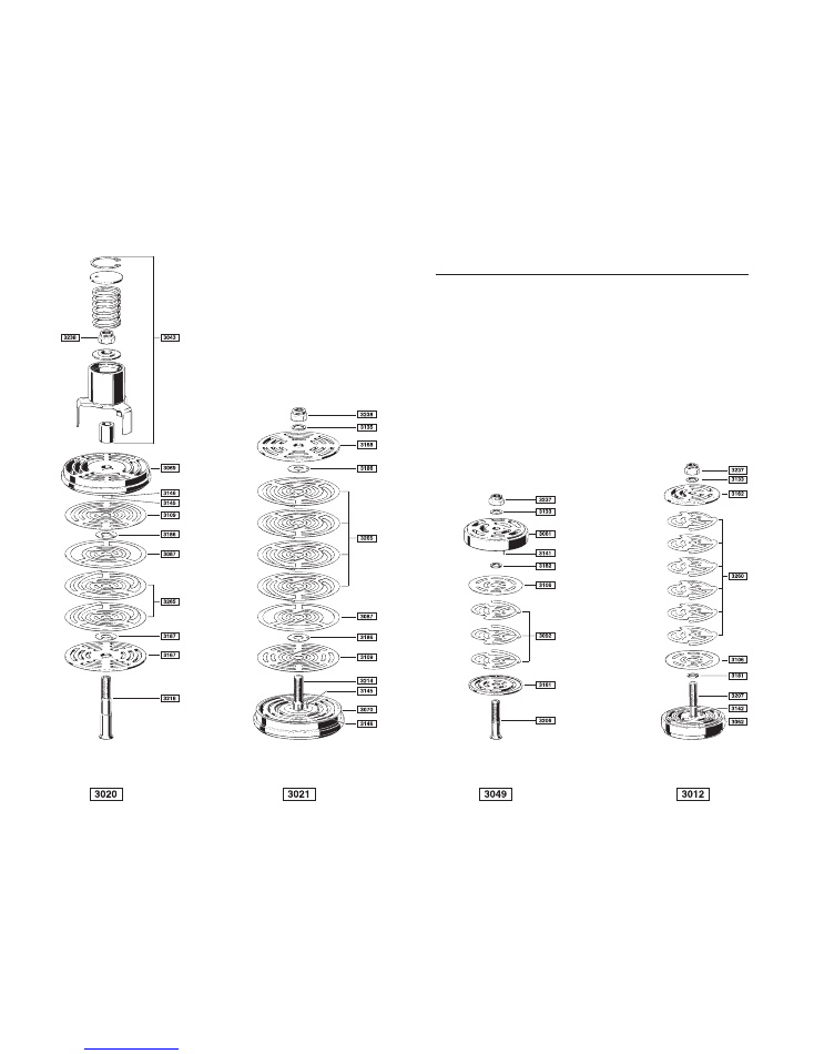
5.2. Valves
In the parts list and drawings each valve is shown complete, with its own part number, and also dismantled with
the part numbers of the individual components.
After overhaul or replacement of parts, assemble the valves in sequence as shown in the drawing of the
dismantled valve.
When assembling valves, lubricate the nut and valve bolt and tighten to the torques (in kpm) given below:
Dimension
Minimum
Maximum
M10
2.00
2.45
M12
3.60
4.40
M14
5.70
6.90
M16
9.00
11.00
IMPORTANT:
Before attempting to check compressor valves, loosen the clamping screw on the valve cover before removing
the cover.
After inspecting and overhauling valves, it is essential that the clamping screw, which bears against the valve
clamping piece and which keeps the valve in place on its seat, should be tightened with an unbrako key to the
torque shown in Table T.3.
Overhaul and mainenance of valves
Regular and careful maintenance of valves is essential to the capacity and reliability of the compressor. We
therefore recommend overhaul in accordance with the following guidelines:
A. When cleaning and dismantling the valve, never clamp the valve directly in a vice to loosen the centre bolt
nut. A special clamping jig for this purpose, suitable for all valves, is available from the factory on request. A
simple makeshift for clamping the valve is to set it in a vice between two pins which fit into the outermost seat
slots of the valve.
B. Clean the valve components and check them carefully.
IMPORTANT
: Never use sharp implements on sealing surfaces and plate parts.
C. Replace all parts that are worn or even slightly scored. Check that all guide pins are in order. Maximum wear
limit is 10% of the total thickness of components.
D. If a valve spring or spring plate shows signs of weak-ness, all springs must be replaced at the same time,
because damage can result if some springs operate longer than others. Replacement of all valve springs is
recommended after about 5000 hours running time, even if the springs do not look worn.
E. If there are signs of abrasion or scoring of the valve seat sealing ledges, these must be machined. Most
valves are drilled for guide pins, with spare holes for new pins. Guide pins can be driven out by means of a
suitable tool. If it proves impossible to remove a broken pin, use one of the spare holes.
F. To remove the valve centre bolt, mark the centre of the pin with a centre punch and then drill out the pin.
Remove the centre bolt. After refitting the bolt, drill a hole for the safety pin, drive the pin securely into place
and peen the end to prevent it from falling out.
G. After completion of machining and careful replacement of guide pins in their respective holes in the valve
seating and/or catch plate, check that the ends of the pins do not but against the bottom of the holes in the
matching parts.
Use
only
genuine replacement pins and parts.
Assembly of valves demands precision, care and forethought. Make sure that the various parts are correctly
located and that the right numbers are installed. Compare with the lists and drawings of parts to ensure that the
right number of parts is present. Total lifting heights of valve plates are given in Table T.4.
Instruction manual for Water-cooled Air Compressor HV2/210 - 8 -
5.3. Lubricating oil system
The lube oil pump is a gear pump which is normally capable of operating for long periods without maintenance.
The pump is directly driven from the end of the crankshaft, and oil pressure is controlled by means of a by-pass
valve in the pump. To overhaul, dismantle the mounting flange and pipe connections, and pull the pump out.
An easily replaceable lube oil filter is fitted between the delivery side of the pump and the compressor.
IMPORTANT:
Accumulation of condensate in the crankcase may present a serious problem under certain
operating conditions, and it is important that the operator should check from the very beginning
whether condensate in the lubricating oil is liable to become a problem.
Unless the condensed water emulsifies with the lubricating oil, it will separate out and there is a risk that the
compressor will be lubricated with water.
The choise of lube oil is of great importance to the reliable operation of the compressor. The manufactorers have
performed extensive tests of lube oils for the oil companies, and the following is a list of lubricants recommended
on the basis of these tests.
A list of recommended types of oil is affixed to the compressor on delivery.
Mineral oil
Syntetic oil
BP ENERGOL RC 68
BP ENERSYN RX 100
CASTROL AIRCOL PD 100
CASTROL AIRCOL SN 100
CALTEX RPM COMPR. OIL 68
CHEVRON HD COMPR. OIL 100
ESSO/ EXXON EXXCOLUB 77
DAPHNE MARINE COMPRESSOR 100
FINA EOLAN AC
ELF PRIMERIA SG 100
GENERAL COMPOL A 100
ESSO/EXXON ZERICE S 100
MITSUBISHI COMPR. OIL 100
ESSO/EXXON SYNTESSTIC 68
MOBIL RARUS 427
MOBIL RARUS 827
NYNÄS COMPR. OIL 68
NIPPON OIL CO. FAIRCOL SA100
PHILLIPS COMPR. OIL 68
SHELL CORENA AP 68
SHELL CORENA P 68
STATOIL COMPWAY S 100
TEXACO SYN STAR DE 100
Further information about lubricants is available on application to the manufacturer.
5.4. Bearings
The compressor has replaceable, two-shell plain big-end and crankshaft bearings. The middle crankshaft
bearings serves as an axial guide for the crankshaft.
The gudgeon pin bearings are single shell plain bearings, press-fitted into the little ends. Tolerances and
clearances for connecting rod, crankshaft and gudgeon pin bearings are given in Table T.4.
All plain bearings are pressure lubricated.
After inspection or replacement of the big-end bearings it is important to ensure that the bearing does not bind on
the crankshaft. It must be possible to turn over the compressor manually.
New two-shell bearings are coated with a running-in compound at the factory.
Dismantling the gudgeon pin bearing from the connecting rod.
A. Use a hydraulic press or extractor to remove the old bearing shell.
B. Press in the new bearing shell.
C. Adjust the fit of the bearing to the gudgeon pin in accordance with Table T.4.

Instruction manual for Water-cooled Air Compressor HV2/210 - 9 -
5.5. Piston and piston rings
Dismantle the piston as follows:
LP piston
A. Remove the cylinder head without dismantling the valves.
B. Remove the big-end bearing bolts and bearings.
C. Withdraw the piston and connecting rod from above.
Assembly sequence is the opposite of the above.
HP piston
AA. Remove the big-end bearing bolts and lower bearing shell. Turn over the crankshaft to top dead centre and
then back. The upper bearing shell can now be removed.
BB. Turn over the crankshaft to bottom dead centre, then withdraw the piston and connecting rod through the
crankcase door.
Assembly sequence is the opposite of the above.
5.6. Flexible coupling
The compressor flywheel serves as one coupling half.
Dismantle the coupling
A. Loosen the nuts on each coupling half and give each one a sharp tap with a hammer before removing them
completely. This will cause the bolts to loosen from their conical holes in the coupling halves.
B. Remove the bolts and take out the flexible coupling. Avoid spilling oil on the flexible coupling.
The coupling half on the motor is keyed and shrunk on to the axle.
Alignment
The prinsiple and values for checking alignment are shown in Fig. 4.
A. Micrometer/dial indicator
B. Magnetic base
C. Flywheel
D. Coupling half, motor
E. Flexible coupling
Check the angle (W) by means of inside micrometer callipers or vernier callipers. The distance (W) in mm should
be the same around the whole circumference of the coupling halves.
Check parallel misalignment (A) between coupling halves as shown, around the circumference of the coupling
halves (C). Values in mm for maximum parallel misalignment are given in Fig.4.

Instruction manual for Water-cooled Air Compressor HV2/210 - 10 -
5.7. Coolers
To ensure reliable operation of the compressor it is important to keep the LP and HP coolers free from deposis of
carbon and cooling water salts etc. Insufficient cooling causes excessive air temperature and progressively
increases the formation of carbon deposits.
The cooling tubes are roller expanded into tube plates at both ends.
The seals at the cooler ends are O-rings, type OF special quality. Use only manufacturer's spares. To remove
the tube bundle, first loosen the cooler covers at both ends. The whole bundle can then be withdrawn by means
of two guide rods, pushed through the tubes.
Assemble in opposite sequence.
Instal new seals.
If the cooling tubes show signs of severe corrosions or wear, the complete cooler should be replaced.
5.8. Filter
The air filter
should be cleaned by means of a good degreasing agent. Blow the filter clean with compressed air
and give it a thin coating of compressor oil.
The oil filter
should be replaced complete. Replacement every 1000 hours running time is recommended.

Instruction manual for Water-cooled Air Compressor HV2/210 - 11 -
6. TECHNICAL DATA
T.1. Coolant flows
Shaft speed rpm.
580
-
725
-
875
-
975
Coolant flow l/min. 7-10 bars................................ :
17
-
21
-
26
-
28
Pressure drop across compressor (mm.w.c.)....... :
110
-
180
-
280
-
350
Coolant flow l/min. 15-35 bars.............................. :
21
-
26
-
32
-
35
Pressure drop across compressor (mm.w.c.)....... :
180
-
280
-
440
-
550
T.2. Recommended pressures and temperatures
Recommended minimum inlet temperature Cooling water .................... : 30
o
C
Recommended maximum outlet temperature Cooling water ................. : 60
o
C
Recommended temperature difference.................................................. : 15 - 20
o
C
Recommended cooling water pressure.................................................. : 0.5 - 3.0 bars
Recommended lube oil pressure, warm compressor ............................. : 2.0 - 0.8 bars
Recommended limit switch setting for lube oil pressure/safety stop ...... : 0.8 bars
Normal working pressure one stage 0-10 bars ...................................... : 1.5 - 3.5 bars
Normal working pressure one stage 10-35 bars .................................... : 4.0 - 6.0 bars
Maximum working pressure.................................................................... : 35 bars
Safety valve setting over stage pressure................................................ : 10%
Normal temperature outlet air................................................................. : 30 - 65
o
C
T.3. Torque table
A - Thread diameter (mm)
B - Key width
C -Torque (kpm), clean and lubricated threads
* - Marker for unbrako screw
** - Marker for BSP threads
Component
A
B
C
Cylinder head ....................................................... :
M20
30
20
Cooler cover ......................................................... :
M16
24
15
Cooler cover ......................................................... :
M12
19
8
Valve cover HP and LP ........................................ :
M16
24
15
Valve clamping screw HP and LP ........................ :
*M20
10
12
Cap lock nut HP and LP ....................................... :
M20
30
10
Big end bearing bolts HP and LP ......................... :
**1/4
22
9-10
Main bearing studs ............................................... :
M12
19
8
Bearing housing, crankcase ................................. :
M10
17
4
Cylinder block to crankcase ................................. :
M22
32
25
Hand hole – Air intake manifold ........................... :
M12
19
8
Crankcase covers................................................. :
M10
17
4

Instruction manual for Water-cooled Air Compressor HV2/210 - 12 -
T.4. Clearances
Suction valve LP Lifting height
(mm)............. : 1.2
Pressure valve LP Lifting height
(mm)............. : 1.2
Suction valve HP Lifting height
(mm)............. : 1.1
Pressure valve HP Lifting height
mm) .............. : 1.4
Cylinder/piston clearance LP
(mm)............. : 0.35
Cylinder /piston clearanse HP
(mm)............. : 0.25
Piston/cylinder head clearance LP (mm)............. : 1.4 - 1.8
Piston cylinder head clearance HP (mm)............. : 1.4 - 1.8
Crankshaft/guide bearing end clearance (mm) .... : 0.3 - 0.5
Main bearing/shaft clearance
(mm)............. : 0.08 - 0.12
Crankshaft bearing play
(mm)............. : 0.08 - 0.11
Gudgeon pin bearing play
(mm)............. : 0.03 - 0.04
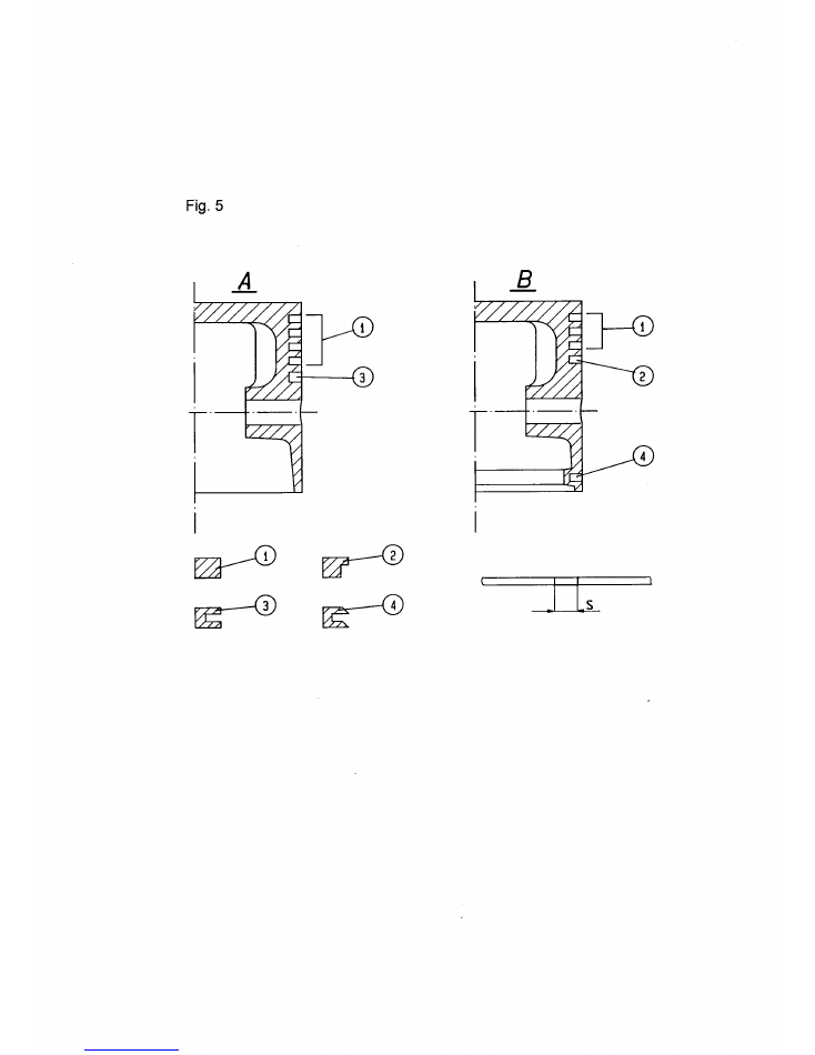
T.5. Piston rings
Pressure stage
LP
HP
Piston illustration (F.5.)......................................... :
B
A
Number of compressor rings ................................ :
2
4
Number of scraper rings....................................... :
2
Number of oil rings ............................................... :
1
1
Min. end clearance S (mm) .................................. :
0.80
0.35
Max. end clearance S (mm) ................................. :
1.05
0.55
Wear limit S (mm) ................................................ :
2.05
1.55
T.6. General data
Number of cylinders
..................... :
2
Cylinder diameter LP
(mm) ............ :
210
Cylinder diameter HP
(mm) ............ :
93
Stroke
(mm) ............ :
110
Crankpin diameter
(mm) ............ :
63
Crankshaft diameter at bearing
(mm) ............ :
63
Gudgeon pin diameter LP
(mm) ............ :
40
Gudgeon pin diameter HP
(mm) ............ :
40
Number of valves LP
..................... :
2
Number of valves HP
..................... :
2
Oil capacity of sump
(litres) .......... :
8

Instruction manual for Water-cooled Air Compressor HV2/210 - 13 -
7. Replacement Parts List - Water Cooled Air Compressor - HV2/210
Part Qty. Description
No.
1012
1
Crankcase
1038
1
Crankcase cover
1041
1
Crankcase cover - dipstick side
1058
1
Bearing housing - flywheel side
1062
1
Bearing housing - lub. oil pump side
1076
1
Flywheel
1103
1
Cylinder block
1153
3
Main bearing shell cups
1163
4
Bearing shell cups, pair
1171
1
Cooler cover - Pos. 1
1175
1
Cooler cover - Pos. 3
1231
1
Frame - bursting plate
1255
1
Cylinder head
1297
1
Air filter duct
1316
2
Valve cover, HP
1318
1
Valve cover, LP suction side
1319
1
Valve cover, LP delivery side
1330
1
Flywheel nut
1366
1
Non return valve cover
1382
1
Coupling flange
1414
1
Connecting rod, LP
1415
1
Connecting rod, HP
1440
2
Inspection hole cover
1441
1
Inspection hole cover with 1/2" hole
1463
2
Clamping piece, HP valve
1471
1
Clamping piece, LP suction valve
1472
1
Clamping piece, LP delivery valve
1516
1
Counterweight
1530
1
Blind plate
2012
1
Crankshaft
2998
1
Non return valve
3245
1
Valve unloader, complete
3304
1
Unloader cover
3311
1
Unloader cylinder
3318
1
Unloader piston
3329
4
Big-end bearing bolt
3335
4
Big-end bearing nut
3340
4
Big-end bearing split pin
3384
1
Piston, LP
3398
1
Piston, HP
3446
1
Connector - pump
3465
1
Gudgeon pin, LP
3468
1
Gudgeon pin, HP
3486
2
Oil scraper ring, LP
3505
4
Compression ring, HP
3519
2
Compression ring, LP
3533
1
Oil ring, HP
3544
1
Oil ring, LP
3577
1
Ball - lub. oil pump
3583
1
Valve spring - lub. oil pump
3606
1
Adjusting screw - lub. oil pump
3634
1
Oil level gauge glas
3643
1
Pressure gauge board
3654
2
Cooler unit
3677
1
Key
Part Qty. Description
No.
3696
3
Cap nut - clamping screw
3697
1
Cap nut - lub. oil pump
3700
1
Breaher valve
3713
1
Air filter unit, complete
3718
1
Air filet insert
3722
1
Oil strainer
3728
1
Oil strainer mesh
3731
1
Oil strainer holder
3741
2
Clamping screw, HP
3742
1
Clamping screw, LP
3746
1
Dipstick
3770
2
Pressure gauge, C.W./lube oil
3771
1
Pressure gauge, LP
3773
1
Pressure gauge, HP
3775
2
Spacer
3781
1
Thermometer
3783
1
Nipple - thermometer
3810
4
Seeger ring
3821
1
Gudgeon pin bearing, LP
3822
1
Gudgeon pin bearing, HP
3832
2
Big-end bearing shell, pair
3852
1
Sealing ring - lub. oil pump
3861
1
Sealing ring - main shaft
3906
5
Valve gasket
3909
2
Valve gasket
3921
2
Main bearing end
3922
1
Main bearing guide
3925
4
Copper washer
3927
8
Copper washer
3928
5
Copper washer
3929 22
Copper washer
3930
6
Copper washer
3932
4
Copper washer
3934
2
Copper washer
3937
4
Lock washer
3946
4
Screw - lub. oil pump
3950
2
Screw - pressure gauge panel
3960
1
Bursting plate
3965
1
Internal lub. oil tube set
3974
4
O-ring - air coolers
3979
1
O-ring - valve unloader
4028
2
Gasket - crankcase / cylinder block
4033
2
Gasket - crank case cover
4034
1
Gasket - bearing housing, oil pump side
4035
1
Gasket - bearing housing, flywheel side
4053
1
Gasket - air outlet flange
4057
2
Gasket - HP valve cover
4058
2
Gasket - LP valve cover
4059
1
Gasket - lub. oil pump
4068
4
Gasket - bursting plate
4070
1
Gasket - cylinder cover
4085
1
Gasket - air filter duct
4099
3
Gasket - cooler cover
4132
1
Backnut
4142
1
T-joint

Instruction manual for Water-cooled Air Compressor HV2/210 - 14 -
Part Qty. Description
No.
4189 34
Stud - crank case covers
4192 16
Stud - inspection hole
4193
4
Stud - bursting disk
4197
6
Stud - main bearing housing
4198
1
Stud - LP separator
4202 10
Stud - cooler cover
4204
2
Stud - cooler cover
4208 16
Stud - valve cover
4209 12
Stud - cooler cover
4215
8
Stud - cylinder block / crank case
4219
6
Stud - cylinder top
4236
4
Nut - drain plate
4237 34
Nut - crank case cover
4238 32
Nut - inspection hatch, cooler cover
4240 44
Nut - cooler cover, valve cover
4242
6
Nut - cylinder top
4253
6
Locknut - main bearings
4257
8
Locknut - cylinder block / crank case
4268
1
Set screw - counter weight
4269
1
Nipple
4271
4
Nipple
4273
2
Nipple
4275
1
Nipple - c.w. inlet
4276
1
Nipple - c.w. outlet
4280
2
Nipple
4294
3
Plug
4296
7
Plug
4297
1
Plug
4298
1
Plug
4361
1
Pressure gauge tube
4364
2
Pressure gauge tube
4367
1
Pressure gauge tube
4372
3
Nipple
4374
1
Reduction nipple
4388
1
Lub. oil tube
4391
1
Lub. oil tube
4407
2
Screw - counterweight
4414
2
Washer - pressure gauge panel
4416
8
Washer - cooler cover
4420
1
Safety valve, HP
4421
1
Safety valve, LP
4433
4
Screw - non return valve cover
4441
1
Lub. oil pump
4446
1
Set screw
4447
1
Set screw
4449
2
Screw
4451
2
Connecting nipple
4471
2
T-joint
4487
6
Coupling bolt
4523
1
Coupling disk
4624
4
Screw - non return valve flange
4673
2
Screw - gudgeon pin bearing
7591
1
Cooler cover - Pos. 2
7593
1
Cooler cover - Pos. 4
7595
1
Separator
7609
1
Cyclone pipe
7620
6
Stud - cooler cover Pos. 2
7645
1
Drain plate
Part Qty. Description
No.
7648
1
Gasket - drain plate
7651
1
Drain trap
7654
1
Drain nipple
7655
1
Guide pin
7657
1
Plug
7659
1
Cap nut
7660
1
Gasket
7664
4
Stud - drain plate
7665
2
Swivel nipple
7747
6
Stud - cooler cover Pos. 4
7750
2
Plug
7754
1
Nipple
Valve parts:
3012
1
Delivery valve, HP complete
3020
1
Suction valve, LP complete
3021
1
Delivery valve, LP complete
3043
1
Valve gripper, LP complete
3049
1
Suction valve, HP complete
3061
1
Valve seat, HP suction
3062
1
Valve seat, HP delivery
3069
1
Valve seat, LP suction
3070
1
Valve seat, LP delivery
3087
2
Damping plate, LP
3092
3
Valve spring, HP suction
3106
2
Valve plate, HP valve
3109
2
Valve plate, LP valve
3133
2
Valve washer
3135
1
Valve washer
3141
1
Fixing pin
3142
1
Fixing pin
3145
2
Fixing pin
3146
2
Fixing pin
3161
1
Valve catcher, HP suction
3162
1
Valve catcher, HP delivery
3167
1
Valve catcher, LP suction
3168
1
Valve catcher, LP delivery
3181
1
Valve spacer ring
3182
1
Valve spacer ring
3186
3
Valve spacer ring
3187
1
Valve spacer ring
3206
1
Valve bolt, HP suction
3207
1
Valve bolt, HP delivery
3214
1
Valve bolt, LP delivery
3218
1
Valve bolt, LP suction
3237
2
Valve nut
3238
2
Valve nut
3260
6
Valve spring, HP delivery
3265
6
Valve spring, LP suction/delivery
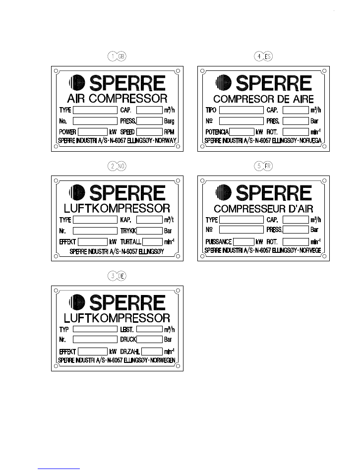
Fig. 1
Instruction manual for Water-cooled Air Compressor HV2/
210
- 1
5
-
Instruction manual for Water-cooled Air Compressor HV2/
210
- 1
6
-
Instruction manual for Water-cooled Air Compressor HV2/
210
- 17 -
Instruction manual for Water-cooled Air Compressor HV2/
210
- 18 -
HV2/200 – HV2/210 – HV2/219
NOV. 2001
Low pressure
suction valve
Low pressure
delivery valve
High pressure
suction valve
High pressure
delivery valve
3927
4193
4447
4296
3929
4420
3929
7648
7645
7664
4236
3929
3929
3929
7654
4273
7651
7591
4271
3927
4416
7655
7595
4202
4238
4240
4198
7620
3932
7657
7660
7659
7665
4296
3519
3505
3533
3398
3468
3486
4204
4238
4624
3716
4053
4433
1366
3906
2998
7609
3906
4240
7747
7593
3932
7665
7750
3929
4296
3906
7754
3544
1038
1041
HV2/210
APRIL 2002
4070
1103
3384