Full Text Searchable PDF User Manual
P/N 315-049430-2
OPERATION
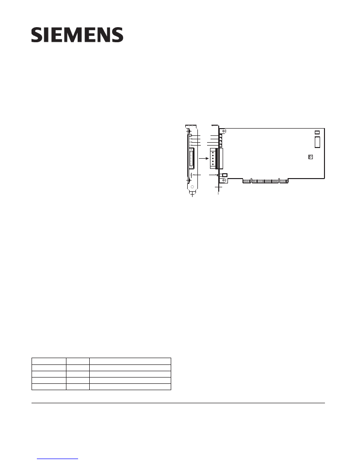
The Model NCC-2F from Siemens Industry, Inc. (as
shown in Figure 1) is a PCI-compliant network card
used with the NCC, NCC WAN and Desigo CC sys-
tems. The NCC-2F allows the user to interface net-
worked MXL and/or XLS fire panels to Desigo CCs
and/or NCCs on XNET. The NCC-2F can also provide
an interface to NCC WAN components, including the
HUB-4 over HNET. An NCC-2F can provide connectiv-
ity to either XNET or HNET, or both XNET and HNET
using 2 cards. The NCC-2F may also be used in an
FVNET setup inside the VNT. This allows for interfac-
ing HNET and XNET between multiple XLS systems.
The NCC-2F provides the NCC and Desigo CC with a su-
pervised RS-485 network connection. The NCC-2F oper-
ates in both Style 4 (Class B) and Style 7 (Class A) modes.
The module fits in any available PCI 5V compliant slot. The
card is keyed so that it will only fit in an appropriate PCI slot.
The module comes preinstalled in NCC and Desigo CC
computers. Hardware installation instructions for the NCC-
2F, when it is not factory installed, can be found in the
Physical Installation
section of this document.
Controls and Indicators
The NCC-2F provides one reset switch and four LEDs that
are accessible through the back of the PC it is mounted
in. The reset switch (S2) is located just below TB1.
Pushing the reset switch initializes the NCC-2F operation.
The LEDs are located above TB1 and are, in top to bot-
tom order:
D
E
L
r
o
l
o
C
n
o
i
t
p
i
r
c
s
e
D
)
2
S
D
(
K
O
T
E
N
n
e
e
r
G
.
a
t
a
d
g
n
i
v
i
e
c
e
r
s
i
k
r
o
w
t
e
n
e
t
a
c
i
d
n
i
o
t
s
k
n
il
B
)
1
S
D
(
K
O
T
S
O
H
n
e
e
r
G
.
ti
m
s
n
a
r
t
o
t
a
t
a
d
e
t
a
c
i
d
n
i
o
t
s
k
n
il
B
)
4
S
D
(
A
H
C
w
o
ll
e
Y
.
t
c
e
l
e
s
A
l
e
n
n
a
h
C
l
a
u
d
i
v
i
d
n
i
e
t
a
c
i
d
n
i
o
t
*
s
k
n
il
B
)
5
S
D
(
B
H
C
w
o
ll
e
Y
.
t
c
e
l
e
s
B
l
e
n
n
a
h
C
l
a
u
d
i
v
i
d
n
i
e
t
a
c
i
d
n
i
o
t
*
s
k
n
il
B
.l
e
n
n
a
h
c
t
a
h
t
n
o
tl
u
a
f
7
e
l
y
t
S
a
s
e
t
a
c
i
d
n
i
,
y
d
a
e
t
s
s
i
D
E
L
f
I
*
Installation Instructions
Model NCC-2F
Network Interface Card
For PCI Application with Windows
Siemens Industry, Inc.
Building Technologies Division
Florham Park, NJ
Siemens Canada, Ltd.
1577 North Service Road East
Oakville, Ontario
L6H 0H6 Canada
NCC-2F
P2
U4
P1
S2
TB1
S1
1
2
3
4
5
1
5
DS2
DS1
DS4
DS5
NET OK
HOST OK
CH A
CH B
SIDE VIEW
RESET
Figure 1
NCC-2F Module Board
CONFIGURATION
The NCC-2F is assigned to a standard COM port by
Windows when the drivers are installed. The drivers
come pre-installed in NCC and Desigo CC computers.
The NCC-2F driver installations are covered in the
Driver Installation
section of this document.
The COM port assigned to the NCC-2F can be viewed
in the Windows Device Manager. One NCC-2F card
occupies two consecutive COM ports, but only one will
be available for use by the NCC-2F. On Windows XP
systems, the used COM port will be the first (or lower)
numbered port assigned for the NCC-2F card. On Win-
dows 7 systems, the used COM port is the NCC-2F
Enhanced Communications Port assigned as Port0
(seen via Properties) - and may be the lower or higher
port number, depending on the computer.
The Device Manager is accessible in Windows as follows:
WINDOWS XP
Click Start >Settings >Control Panel >Administrative
Tools >Computer Management >Device Manager.
Another way is to right click My Computer icon, then
select Properties >Hardware >Device Manager.

2
Figure 2 shows a sample Windows XP Device Manager
view and a typical assignment of COM ports on a PC
with (2) NCC-2F boards installed. The port assignments
for the NCC-2F are labeled
PCI Communications Port
.
Figure 2
Windows XP Device Manager View
WINDOWS 7
Open the Start menu, then click on Control Panel; this
will open a new window on the Desktop, showing the
Control Panel options.
Figure 3
Windows 7 Device Manager View
The Address bar of the Control Panel window should
end with the “Control Panel” location, followed by a
“right-arrow”.
Click on the “right-arrow” to display the available addi-
tional locations, then select All Control Panel Items,
and click on it. On the updated screen, select Device
Manager and click on it.
Figure 3 shows a sample Windows 7 Device Manager
view and a typical assignment of COM ports on a PC
with (1) NCC-2F board installed. The port assignments
for the NCC-2F are labeled Enhanced Communication
Port, once installed.
In these examples above, the first NCC-2F is assigned
to ports COM3 and COM4, and the second NCC-2F is
assigned to ports COM5 and COM6. This is the default
setup, with XNET on COM3 (the first port of the first
board) and HNET on COM5 (the first port of the second
board).
The NCC or Desigo CC XNET (and HNET) port as-
signment can be changed to agree with any port assign-
ment at the time of install or update. Either board can
handle XNET and either board can handle HNET. There
is no difference in the boards. However, XNET and
HNET are different protocols, so HNET wiring should
go to the board with the COM port assigned to HNET
and, likewise, XNET wiring should go to the board with
the COM port assigned to XNET.
PHYSICAL INSTALLATION
Remove all Windows PC power before installation.
To install the NCC-2F in a computer in which it is not
factory installed, follow the steps listed below:
1. Unscrew the two knurled knobs on the rear of the
NCC or Desigo CC computer (computer enclosure
may have different physical characteristics.).
2. Slide the cover back an inch or so and lift it off.
3. The NCC-2F installs into any free PCI 5V compliant
slot in the computer. Select a slot and remove the
blank cover, keeping the screw.
4. Remove the terminal block from the NCC-2F by
removing the two screws that hold it to the bracket.
5. Place the NCC-2F into the open slot so that the
NCC-2F card edge extends through the opening in
the back of the PC.
6. Align the NCC-2F with the card edge connector in
the computer and press it firmly into place.
7. Secure the NCC-2F by installing the screw that
held the blank cover. (Refer to Step 3.)
8. Replace the computer cover and tighten the
knurled knobs (or equivalent).
3
9. Reattach the terminal block by sliding it onto the
NCC-2F card edge and install the two screws. This
is a keyed connection and will only install one way.
10. After the NCC-2F is installed, install the NCC-2F
drivers following the instructions in the
Driver
Installation
section of this document.
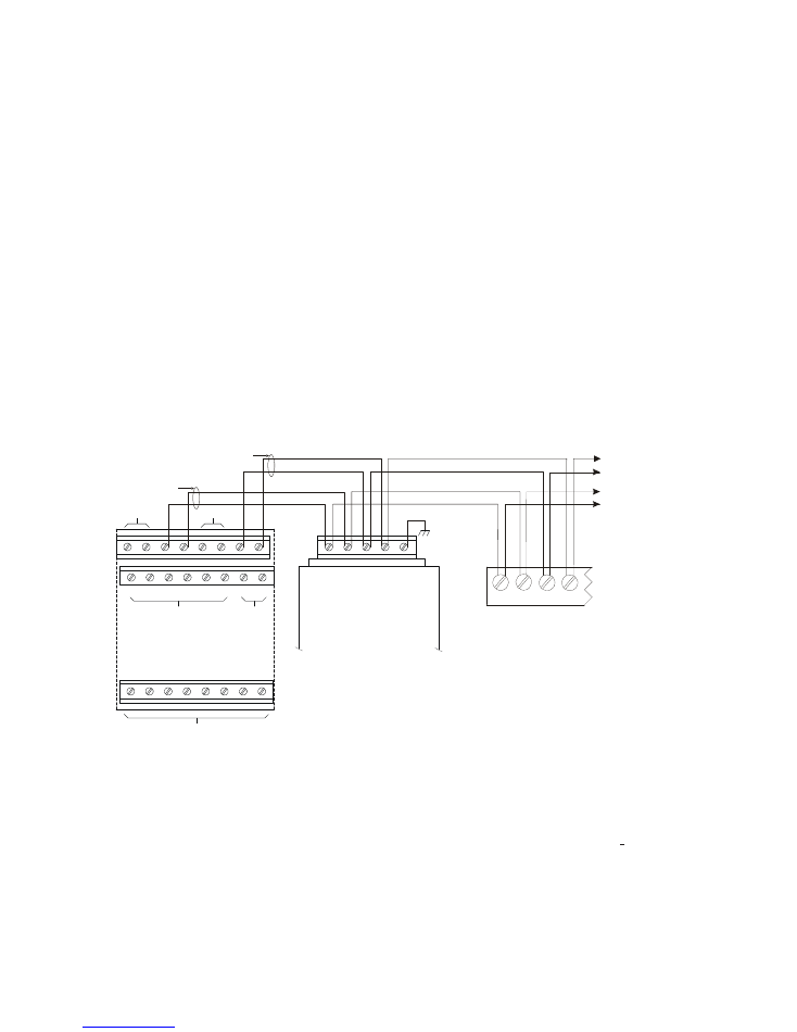
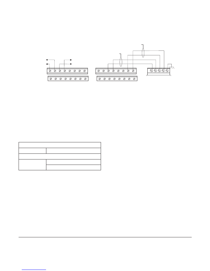
ELECTRICAL CONNECTIONS
Network (XNET)
The XNET connections are made on terminals 1-4 of the
terminal block on the rear of the NCC-2F. The primary
pair (or network A) is on terminals 1 and 2. The second-
ary pair (or network B) is on terminals 3 and 4.
For Style 4
networks,
install a 120 ohm EOLR on ter-
minals 3 and 4. See Figure 4 for wiring details.
For Style 7 networks,
connect to both the primary and
secondary pairs. See Figure 4 for wiring details.
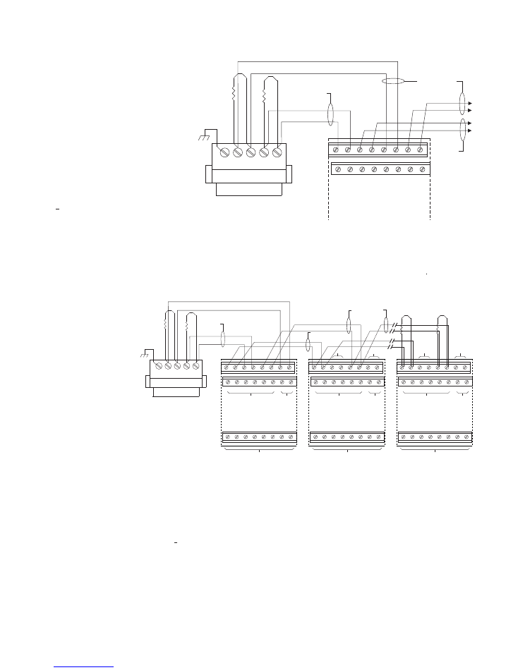
Network (HNET)
The HNET connections are made on terminals 1-4 of the
terminal block on the rear of the second NCC-2F. The
primary pair (or network A) is on terminals 1 and 2. The
secondary pair (or network B) is on terminals 3 and 4.
Install a 120 ohm EOLR on terminals 1 and 2, and on
terminals 3 and 4.
For Style 4
networks,
connect only the primary pairs.
See Figure 5 for wiring details.
For Style 7 networks,
connect to both the primary and
secondary pairs. See Figure 5 for wiring details.
Network (HNET-VNT)
For Style 4
networks,
connect only the primary pairs.
See Figure 6 for NCC-2F HNET-VNT connections.
For Style 7 networks,
connect to both the primary and
secondary pairs. See Figure 6 for wiring details.
1
2
3
4
5
6
7
8
9
10
11
12
13
14
15
16
17
18
19
20
21
22
23
24
SEE NOTE 7
(MUST BE IN SAME ENCLOSURE AS THE PMI)
DO NOT USE
DO NOT USE
DO NOT USE
DO NOT USE
ONE SLOT OF CC-5
NIC-C
1
2
3
4
5
PAIR A
SUPERVISED
POWER LIMITED
PAIR B
(OMIT FOR STYLE 4)
SUPERVISED
POWER LIMITED
LOCATED INSIDE NCC/
DESIGO CC/VNT
NOTE:
IF THE NCC/DESIGO CC/VNT
IS LOCATED AT THE END OF THE
XNET NETWORK, INSTALL EOLR
P/N 140-820350 ACROSS
TERMINALS 1 & 2 AND 3 & 4.
NCC-2F
MOM-4
TB3 OR TB4
NIM-1R / NIM-1W
1
2
3
4
TO ADDITIONAL
NIM-1Rs, NIM-1Ws,
NCC-2Fs OR NIC-Cs
Figure 4
NCC-2F XNET Connections
Refer to Wiring Specification for MXL, MXL-IQ
and MXLV Systems, P/N 315-092772 revision
6 or higher, for additional wiring information.
NOTES:
1.
No EOLR required for NIC-C.
2.
The screw terminals can accommodate one 12-24AWG or two 16-
24AWG.
3.
From the NCC-2F to NIM-1R, NIM-1W or NCC-2F:
80 Ohms max. per pair.
Unshielded twisted pair - .5
μ
F line to line
Shielded twisted pair - .3
μ
F line to line, .4
μ
F line to shield
4.
From the NCC-2F to NIC-C:
2000 feet (33.8 ohms) max. per pair between CC-5s/CC-2s.
Unshielded twisted pair
.25
μ
F max. line to line
Shielded twisted pair
.15
μ
F max. line to line
.2
μ
F max. line to shield
5.
Use twisted pair or twisted shielded pair.
6.
Terminate shields at one end only.
7.
Power limited to NFPA 70 per NEC 760.
8.
CC-5 terminals 9 - 14 are not connected and can be used to tie shields
together.
9.
Positive or negative ground fault detected at <10K ohms on pins 3-4,
7-8 of the NIC-C.
10.
Each pair independently supervised.
11.
Maximum voltage 8V P-P.
12.
Maximum current 75mA during message transmission.
4
Figure 5
NCC-2F HNET Connections
5
NCC-2F
TB1
2
3
4
*
*
1
NETWORK A
(PRIMARY)
SUPERVISED
NETWORK A
(PRIMARY)
SUPERVISED
NETWORK B
(SECONDARY)
SUPERVISED
OMIT THIS PAIR
FOR STYLE 4
1
2
3
4
5
6
7
8
9
10
11
12
13
14
15
16
ONE SLOT OF CC-5
NIC-C
* EOLR 120 OHMS, 1/2W, 5%
P/N 140-820350
NOTES:
1. The screw terminals can accommodate one
12-24AWG or two16-24AWG.
2. From the NCC-2F to NIC-C:
2000 feet (33.8 ohms) max. per pair between
CC-5s/CC-2s.
Unshielded twisted pair
.25
μ
F max. line to line
Shielded twisted pair
.15
μ
F max. line to line
.2
μ
F max. line to shield
3. Use twisted pair or twisted shielded pair.
4. Terminate shields at one and only one NIC-C.
5. Power limited to NFPA 70 per NEC 760.
6. Maximum voltage 8V P-P.
7. Maximum current 75mA during message
transmission.
8. Each pair independently supervised.
9. Positive or negative ground fault detected at
<10K ohms on pins 1-2, 3-4, 5-6, 7-8 of the
NIC-C.
Figure 6
NCC-2F-HNET-VNT Wiring on FCC Only
NOTES:
1. The screw terminals can
accommodate one 12-24AWG
or two16-24AWG.
2. From the NCC-2F to NIC-C:
2000 feet (33.8 ohms) max.
per pair between CC-5s/CC-2s.
Unshielded twisted pair
.25
μ
F max. line to line
Shielded twisted pair
.15
μ
F max. line to line
.2
μ
F max. line to shield
3. Use twisted pair or twisted shielded pair.
4. Terminate shields at one and only one NIC-C.
5. Power limited to NFPA 70 per NEC 760.
6. Maximum voltage 8V P-P.
7. Maximum current 75mA during message transmission.
8. Each pair independently supervised.
9. Positive or negative ground fault detected at <10K ohms on pins 1-2, 3-
4, 5-6, 7-8 of the NIC-C.
10. For Style 4, remove jumper P2 on all NIC-Cs except on the NIC-C that is
connected to the NCC-2F card. For Style 7, remove jumpers P2 and P4 on
all NIC-Cs except on the NIC-C that is connected to the NCC-2F card.
1
2
3
4
5
6
7
8
9
10
11
12
13
14
15
16
17
18
19
20
21
22
23
24
SEE NOTE 7
DO NOT USE
DO NOT USE
DO NOT USE
DO NOT USE
ONE SLOT OF CC-5/CC-2
FIRST NIC-C
1
2
3
4
5
6
7
8
9
10
11
12
13
14
15
16
17
18
19
20
21
22
23
24
SEE NOTE 7
DO NOT USE
DO NOT USE
NETWORK A
(PRIMARY)
SUPERVISED
ONE SLOT OF CC-5/CC-2
1
2
3
4
5
6
7
8
9
10
11
12
13
14
15
16
17
18
19
20
21
22
23
24
SEE NOTE 7
DO NOT USE
DO NOT USE
ONE SLOT OF CC-5/CC-2
LAST NIC-C
NCC-2F
2
3
4
*
1
NETWORK A
(PRIMARY)
SUPERVISED
* EOLR 120 OHMS, 1/2W, 5%
P/N 140-820350
DO NOT USE
DO NOT USE
*
* EOLR 120 OHMS, 1/2W, 5%
P/N 140-820350
*
5
TB1
*
NETWORK B
(SECONDARY)
SUPERVISED
OMIT THIS PAIR
FOR STYLE 4
5
Shields
Shields for the XNET/HNET must be connected at ONE
and ONLY ONE end of the network.
Earth Ground
A good earth ground must be provided for proper tran-
sient protection of the NCC-2F and the NCC or Desigo
CC computer. Connect a separate ground to terminal 5
on the NCC-2F. See Figure 4, 5 or 6 as applicable.
Ground Fault Detection
The NCC-2F provides electrical isolation between the
NCC or Desigo CC computer and the XNET. This al-
lows for ground fault detection to be enabled on the
XNET. Ground fault detection is only possible if ALL
NCC or Desigo CC computers in the system are con-
nected to XNET with an NCC-2F (or NCC-1Fs for exist-
ing NCC systems).
Ground fault detection must be enabled at a
NIM-1R/-1W or NIC-C. Select one and only one NIM-1R/
-1W or NIC-C in the system where the ground fault is to
be detected. You must locate the NIM-1R/-1W in a cabi-
net with either an MMB, SMB or a PSR-1. See Figure 7
for the wiring diagram.
If the XNET is divided into multiple sections of copper
wire using fiber optic segments, ground fault detection
can be enabled at one NIM-1R/-1W or NIC-C for each
section of copper wire. Refer to the NIC-C Installation
Instructions, P/N 315-033240 if you wish to use the
NIC-C to provide ground fault detection.
For ground fault detection on HNET systems,
refer to
the NIC-C Installation Instructions, P/N 315-033240.
DRIVER INSTALLATION
The products which utilize the NCC-2F cards run on
MicroSoft Windows NT, XP and Windows7 operating
systems (OS). The Windows OS type used must be in
accordance with the product to be used (i.e. NCC or
Desigo CC). The drivers are distributed with the instal-
lation disks for the product software.
In the following procedures, there is a reference to a
“driver folder”. For both types of installation disks, use
the folder with the Oxford UART drivers. The exact (drive)
path for this folder is identified in the steps below, and
the drive letter that begins the path should reflect the
designation for the CD/DVD drive being used for software
installation.
When a PC with an NCC-2F card is first started, the card
is detected by Windows. Depending on the Windows
operating system type, a different user-interaction is
required to install the drivers.
Windows XP (NCC)
Driver folder:
D:\drivers\NCC2F_DRIVERS\OXUART_v512_Drivers
Load the disk in the CD-ROM drive, and use the following
instructions for installing the drivers. For each NCC-2F
card in the computer, Windows automatically prompts
the user for drivers. There are three drivers to install: one
for the PCI card UART and two for the PCI communi-
cation ports. You will repeat the outlined installation
steps a total of three times.
If two NCC-2F cards are physically installed: After the
first card is installed, the presence of the second NCC-2F
card will cause Windows to prompt the user for the drivers.
For the second NCC-2F card, follow the same steps as
practiced for the driver installation of the first NCC-2F card.
When all is complete, refer to the Device Manager to
check the COM port designations, and view any instal-
lation issues.
The following steps take you through the process:
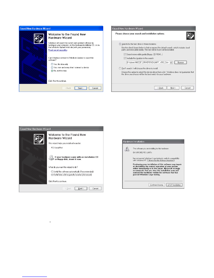
1. When the NCC-2F is first installed, Windows detects
the new hardware. Refer to Figure 8.
At this point select the “No, not this time” option and
click on Next>.
TB3
NIM-1R/-1W
IN TB4
NIM-1R/-1W
IN TB3
USE ONLY ONE
TB5
TB4
MOM-2
MOM-4
TB7
TB4
13
14
15
16
9
10
11
12
13
14
15
16
12
13
14
15
16
12
5
6
7
8
+
1
1
2
2
3
4
_
+
1
2
_
Figure 7
Wiring for Ground Fault Detection (XNET)
6
Figure 8
Found New Hardware Wizard
2. Select “Install from a list or specific location (Ad-
vanced)” and then click Next>. Refer to Figure 9.
Figure 9
Install From A List Or Specific Location
3. Select Next> and search for the CD-ROM drive
where the OXUART_v512_DRIVERS folder is located
(exercised via the Browse button). Refer to Figure 10.
Figure 10
Choosing Search and Installation Options
4. After you highlight the folder (when in Browse), click
“OK” to proceed. Now that the path is set, click Next>.
Windows XP will install the appropriate drivers. When
you see the following Hardware Installation warning,
click “Continue Anyway.” Refer to Figure 11.
Figure 11
Hardware Installation Warning
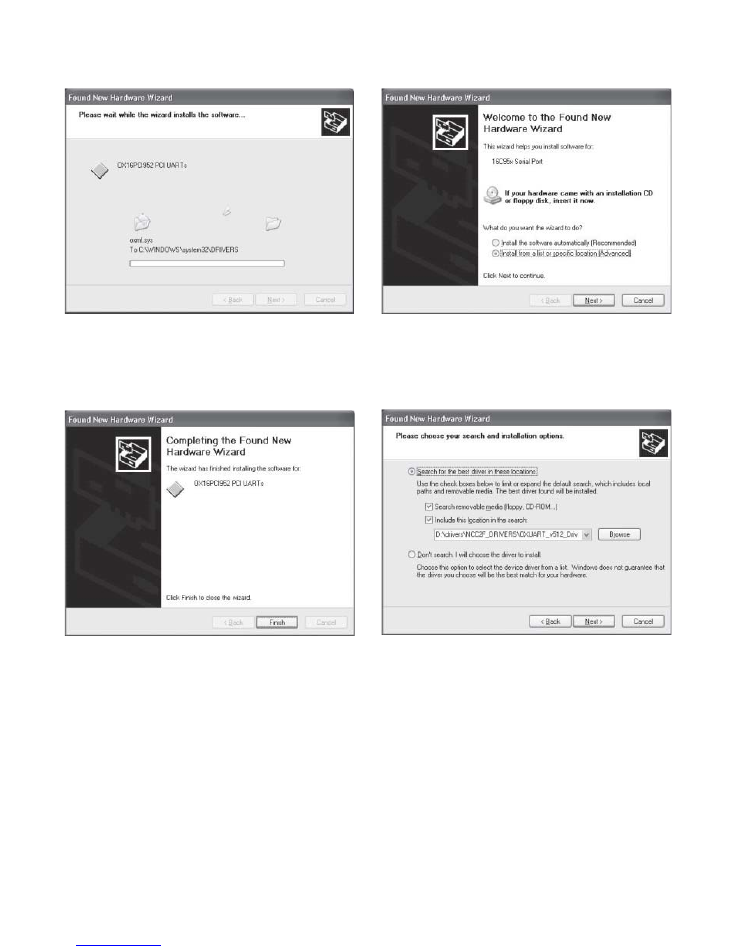
5. The Windows XP Hardware Wizard then installs the
drivers as shown in Figure 12.
7
Figure 12
Installing Drivers Window
6. If the drivers were successfully installed, a message
as shown in Figure 13 is displayed.
Figure 13
Successful Driver Installation
7. Click “Finish”. Windows then prompts the user to in-
stall the drivers for the serial port. Refer to Figure 14.
Note: Windows XP will use the first available COM port
for communication.
Figure 14
Install From A List Or Specific Location
8. Select “Next>” and search for the folder where the
OXUART_v512_DRIVERS
are located. Refer to Figure 15.
Figure 15
Choosing Search and Installation Options
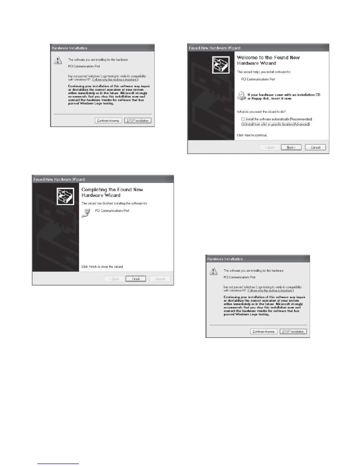
9. After you highlight the folder, click “OK” to proceed.
Now that the path is set, click Next>. Windows XP then
installs the appropriate drivers. When you see the Hard-
ware Installation warning, click “Continue Anyway.”
Refer to Figure 16.
8
Figure 16
Hardware Installation Warning
10. If the drivers were successfully installed, a message
as shown in Figure 17 is displayed.
Figure 17
Successful Driver Installation
11. Click “Finish”. Windows XP then prompts the user to
install the drivers for the additional PCI Communications
Port. Refer to Figure 18.
Figure 18
Install From A List Or Specific Location
12. Select Next> and search for the CD-ROM drive
where the OXUART_v512_DRIVERS folder is located.
13. After you highlight the folder, click “OK” to proceed.
Now that the path is set, click Next>. Windows XP will
install the appropriate drivers. When you see the fol-
lowing Hardware Installation warning, click “Continue
Anyway.” Refer to Figure 19.
Figure 19
Software Installation Warning
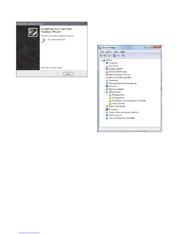
14. If the drivers were successfully installed, a message
as shown in Figure 20 is displayed.
9
Figure 20
Successful Driver Installation
15. To verify which COM ports were installed and to
check that there are no issues, access the Device Man-
ager. The Device Manager can be accessed as de-
scribed in the
CONFIGURATION
section, or equivalent
methods available in Windows XP (i.e. via “My Com-
puter” on the Desktop, selecting “Properties, then
clicking the “Hardware” tab).
16. Once in “Device Manager”, click the “+” sign next to
Ports (COM & LPT) as well as Multifunction adapters.
One should then see a screen similar to that shown in
Figure 2. That example displays two NCC-2F cards in-
stalled. They are configured in pairs, i.e., COM 3 and
COM 4 are the first NCC-2F and COM 5 and COM 6
are the second NCC-2F. The NCC uses COM 3 for the
first card and COM 5 for the second card.
Windows 7 (Desigo CC)
Driver folder:
D:\drivers\NCC2F_DRIVERS\OX95x_Windows\Windows
7\UART\amd64
Load the disk in the CD-ROM drive, and adhere to the
following instructions for installing the drivers.
When all is complete, refer to the Device Manager to
check the COM port designations, and view any instal-
lation issues.
The following steps take you through the process:
1. When the NCC-2F card is first installed, Windows 7
detects the new hardware. To verify the detected hard-
ware, access the Device Manager, as described in the
CONFIGURATION section, or equivalent methods avail-
able in Windows 7 (i.e. via ControlPanel/ System
AndSecurity/System address, where a Device Manager
link can be found in top left of window). The screen in
Figure 21 represents an addition of a single NCC-2F card.
Figure 21
Device Manager Displaying One NCC-2F Card
Notes:
1. Windows 7 groups improperly configured hardware
under Other Devices
2. The NCC-2F has added a 2
nd
PCI Serial Port entry (other
entries correspond to unconfigured hardware,
previously in the PC)
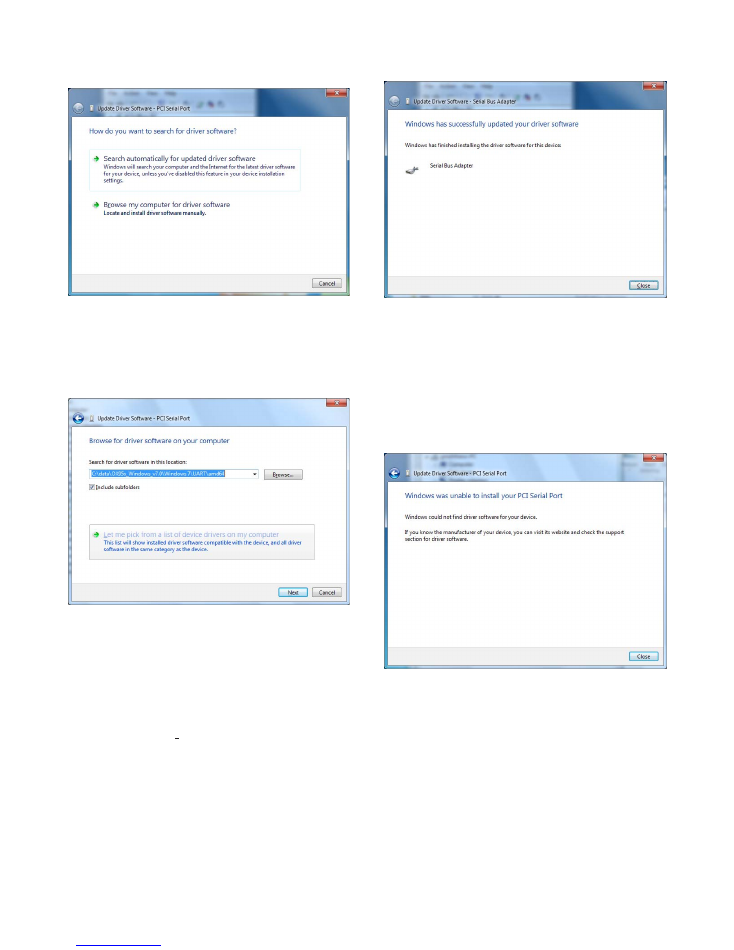
2. Select one of the PCI Serial Port entries in Other
Devices, and right-click on it. A menu (attached to the
selection) appears, where an “Update Driver Software…”
entry appears - click on this entry. A screen as shown in
Figure 22 displays.
1 0
Figure 22
How To Search For Driver Software
3. Click on the “Browse my computer for driver software”
selection. A screen as shown in Figure 23 displays.
Figure 23
Browse For Driver Software
Notes:
1. The screen shows a folder in the C: drive, which will
differ based on the PC being installed.
3. Search for the Oxford UART folder on the installation
CD/DVD, using the Browse button. Once found - select
it, and the correct path for the driver location is shown as
in the previous screen.
4. Click on “Next>”, which prompts Windows 7 to at-
tempt the installation of the driver based on the selected
folder. After a driver install, one of two screens, as
shown in Figures 24 or 25 displays.
Figure 24
Successful Driver Installation
Notes:
1. The screen above reflects a good install, where the
correct PCI Serial Port entry was selected from the
Device Manager’s entry under Other Devices.
2. The screen below reflects an incorrect Device Manager
(PCI Serial Port) entry is selected (i.e. does not
correspond to the NCC-2F hardware).
Figure 25
Unsuccessful Driver Installation
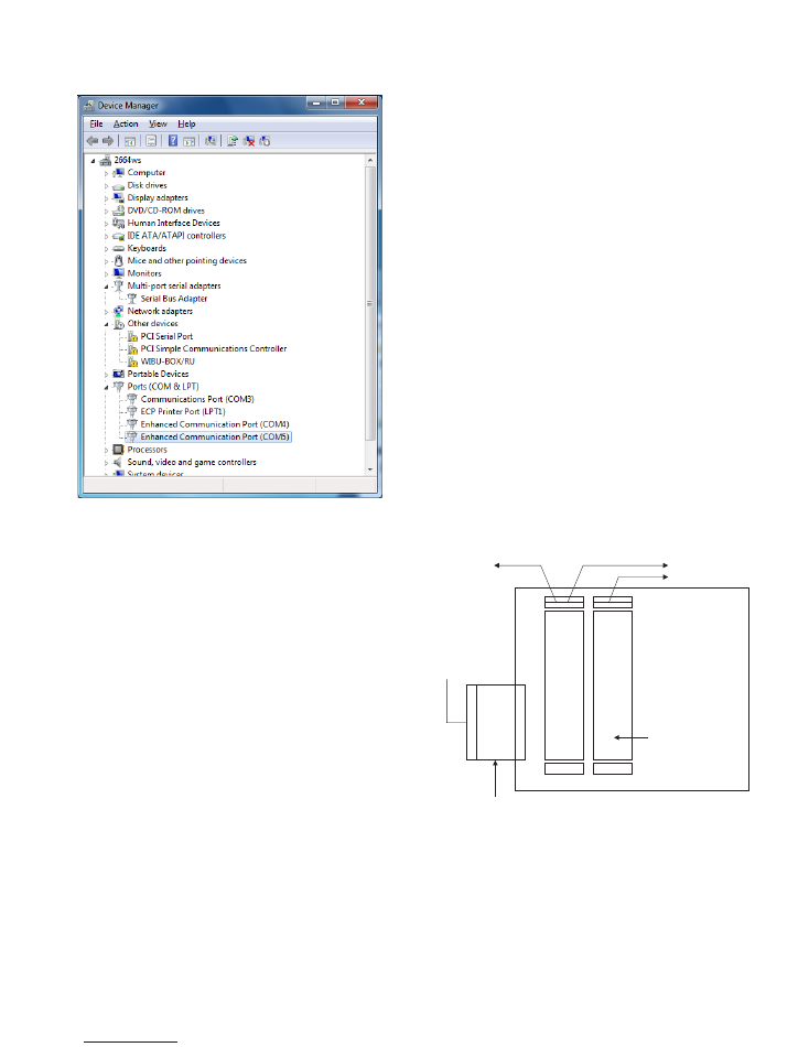
5. To verify which COM ports were installed and to check
that there are no issues, verify the Device Manager en-
tries. Clicking on the Close button in the “Update Driver
Software”, returns to the Device Manager and displays a
screen as shown in Figure 26, for a successful install.
1 1
Figure 26
Verify Device Manager Entries
Notes:
1. A “Multi-port serial adapters” entry now appears, which
shows a “Serial Bus Adapter” entry (can be accessed by
clicking on the arrow symbol to the left of the entry)
represents the NCC-2F hardware.
2. The “Ports (COM & LPT)” entry now shows (when
expanded) the COM ports associated with the two NCC-
2F card ports, Enhanced Communication Port (COM4
and COM5).
3. Under Other Devices, other detected hardware not
handled by this install may still appear (as shown above,
including a non-NCC-2F PCI Serial Port).
The driver installation procedure should now be complete
and any installation media in the CD/DVD-ROM drive
can be removed.
NRC BASED XNET CONNECTION
When an NCC or Desigo CC connects to a NRC-based
XNET network of FireFinder-XLS products, the NCC-
2F card requires additional interface hardware. In such
an installation, the NCC-2F card connects to a NIC-C
module – which in turn is connected to a dedicated
NRC module.
Connect an NCC or Desigo CC to an XLS network system
(rev. PMI07.00 or higher) using NRC network cards in-
stead of a NIC-C as described in the following information.
Add a separate CC-2 or CC-5 card cage to one node on
the XLS network system.
Connect this cage to the XLS network system node using
a 60 pin ribbon cable (BCL). At the added CC-2 or CC-5
card cage, add and secure into connector P1 an Interface
Isolation Card (IIC). (Refer to Installation Instructions, P/N
315-050328.) Plug the other end of the 60 pin cable into
the male ribbon cable receptacle on the IIC.
Insert another NRC and a NIC-C into this isolated card
cage. Do not enter these cards into the Zeus configura-
tion for this node or for the network system. Only the
NCC or Desigo CC is added to the Zeus configuration
as a network node. Note that this NRC is another (sec-
ond NRC) card required for communicating with the
NCC or Desigo CC.
Wire the NRC so that it is inserted into the XLS network
ring. Refer to Figures 27 and 28 as well as the NRC In-
stallation Instructions, P/N 315-050337. Connect the
NCC-2F to the NIC-C as shown in Figure 28. Connect
Pair A for Style 4 and Pairs A and B for Style 7. Address
the NIC-C at address 003.
NRC
CC-2/CC-5
IIC
NIC-C
TO NEXT NRC
FROM PREVIOUS NRC
60 PIN CABLE
FROM PREVIOUS
XLS CARD CAGE
NIC ADDRESS
NOT USED
SET AT 003
INTERFACE ISOLATION CARD
(ISOLATES CARD CAGE SO ONLY
POWER IS USED FROM LOCAL NODE)
TO NCC/DESIGO CC STYLE 4/7
Figure 27
NRC To NCC/Desigo CC Card Cage Connections
P/N 315-049430-2
Siemens Industry, Inc.
Building Technologies Division
Florham Park, NJ
Siemens Canada, Ltd.
1577 North Service Road East
Oakville, Ontario
L6H 0H6 Canada
ELECTRICAL RATINGS
r
e
w
o
P
t
u
p
n
I
F
2
-
C
C
N
A
m
0
5
2
@
C
D
V
5
r
e
w
o
P
t
u
p
t
u
O
T
E
N
X
/
T
E
N
H
h
c
a
E
.
x
a
m
k
a
e
p
o
t
k
a
e
p
V
8
)
n
o
i
s
s
i
m
s
n
a
r
t
g
s
m
g
n
i
r
u
d
(
.
x
a
m
A
m
5
7
1
NCC-2F
4
3
5
B1
A1
B2
A2
1
2
3
4
5
6
7
8
1
2
3
4
5
6
7
8
9
10
11
12
13
14
15
16
9
10
11
12
13
14
15
16
ONE SLOT OF CC-5
ONE SLOT OF CC-5
NIC-C
NRC
PAIR A
SUPERVISED
POWER LIMITED
PAIR B
SUPERVISED
POWER LIMITED
FROM NRC
IN
LOCAL XLS
TO
NEXT
NRC
2
Figure 28
NRC XNET To NCC-2F Connections
NOTES:
1.
For this configuration, only one NCC-2F card
can be connected to the NIC-C card.
2.
For an NRC-based XNET network, each
NCC or Desigo CC node requires a
dedicated NRC/NIC-C in a CC-2 or CC-5
card cage.
Document ID A6V10283733