Full Text Searchable PDF User Manual
1
SJ-V35L
SJ-V39L
SERVICE MANUAL
SX026SE40BPST
SHARP CORPORATION
REFRIGERATOR-FREEZER
Refrigerant; HFC-134a
Refer to "HFC-134a COOLING UNIT" Service Manual for handling this refrigerant.
DESTINATION ............................. T
In the interests of user-safety (Required by safety regulations in some
countries) the set should be restored to its original condition and only
parts identical to those specified should be used.
MODELS
TABLE OF CONTENTS
page
SPECIFICATIONS ............................................................................................................................................. 2
DESIGNATION OF VARIOUS PARTS ............................................................................................................... 4
LIST OF ELECTRICAL PARTS .......................................................................................................................... 6
WIRING DIAGRAM ............................................................................................................................................ 7
FUNCTIONS .......................................................................................................................................................9
DEODORIZING OPERATION .......................................................................................................................... 12
ASSEMBLING PROCEDURES OF MAIN PARTS AND CAUTIONS ............................................................... 13
COOLING UNIT ............................................................................................................................................... 18
REPLACEMENT PARTS LIST ......................................................................................................................... 19
SJ-V39L
SJ-V35L
SJ-V35L-GY
SJ-V39L-GY
2
SJ-V35L
SJ-V39L
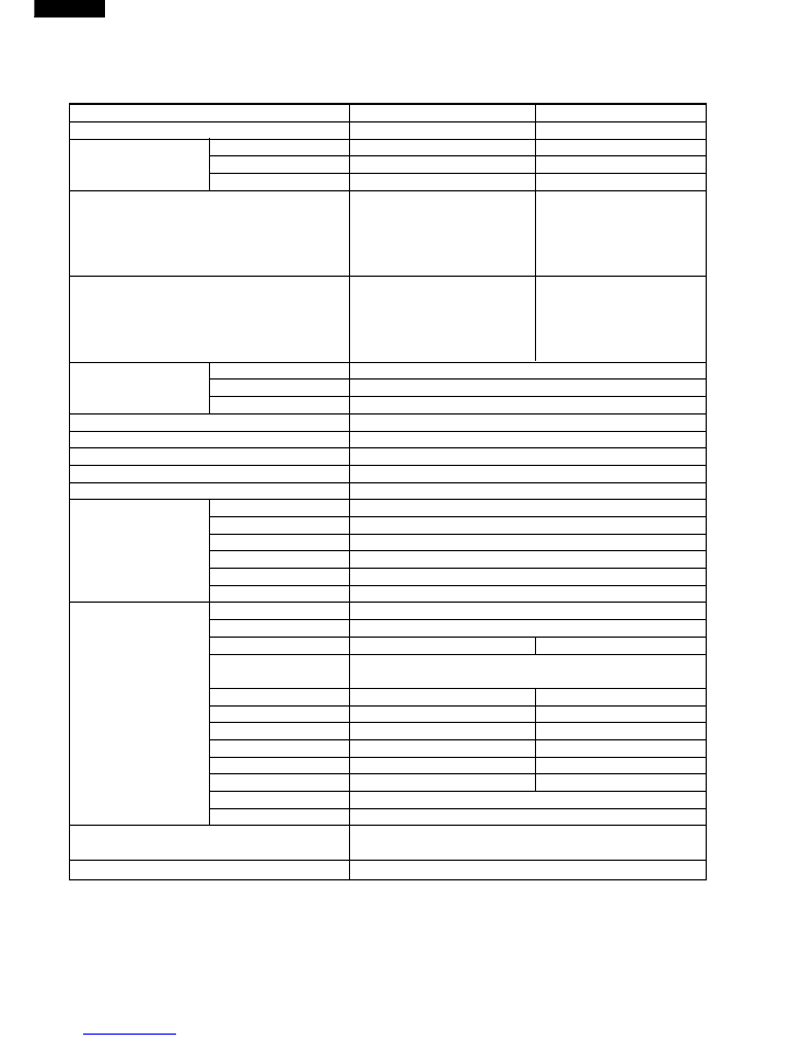
Items
SJ-V35L
SJ-V39L
Type
3-Door
3-Door
Outer dimensions
Height
1578mm(62.2")
1777mm(70.0")
Width
635mm(25.0")
635mm(25.0")
Depth
670mm(26.4")
670mm(26.4")
Rated storage volume
315 liter(11.1 cu.ft)
368 liter(13.0 cu.ft)
F: 88 liter(3.1 cu.ft)
F: 88 liter(3.1 cu.ft)
R: 142 liter(5.0 cu.ft)
R: 195 liter(6.9 cu.ft)
V: 85 liter(3.0 cu.ft)
V: 85 liter(3.0 cu.ft)
Rated gross volume
318 liter(11.2 cu.ft)
371 liter(13.1 cu.ft)
F: 89 liter(3.1 cu.ft)
F: 89 liter(3.1 cu.ft)
R:143 liter(5.1 cu.ft)
R: 196 liter(7.0 cu.ft)
V: 86 liter(3.0 cu.ft)
V: 86 liter(3.0 cu.ft)
Defrosting
System
Heater system
Start
Automatic
Finish
Automatic
Temperature control
Automatic (Adjustable)
No-frost freezer
Yes
Interior lamp
1
Caster
4
Evaporating pan
1
Freezer
Freezer shelf
2
Compartment
Freezing room
1
Ice cube maker
1
Ice cube box
1
Freezer pocket (S)
1
Freezer pocket (L)
1
Refrigerator
Chilled case
1
Compartment
Refrigerator shelf(S)
1
Refrigerator shelf(L) -
1
Three position
1
adjustable shelf
Egg pocket
1
-
Egg holder(S)
1
-
Egg holder(L)
1
2
Utility pocket
1
-
Utility pocket
-
3
Small pocket
-
3
Bottle pocket (S)
1
Bottle pocket (L)
1
Vegetable Compartment
Yes
(Vegetable case 1, Parting Plate 1, Fruit case 1)
Deodorizing system
Yes
SPECIFICATIONS
3
SJ-V35L
SJ-V39L
RATING
Items
SJ-V35L
SJ-V39L
Rated voltage
(V~)
220-240
Rated frequency
(Hz)
50
Climate class
T
Rated input
(W)
139-145
165-175
Rated input of heating elements
(W)
128-152
Defrosting input
(W)
128-152
Refrigerant (Charging quantity)
HFC-134a(115g)
HFC-134a(120g)
Net weight
(kg)
69
73
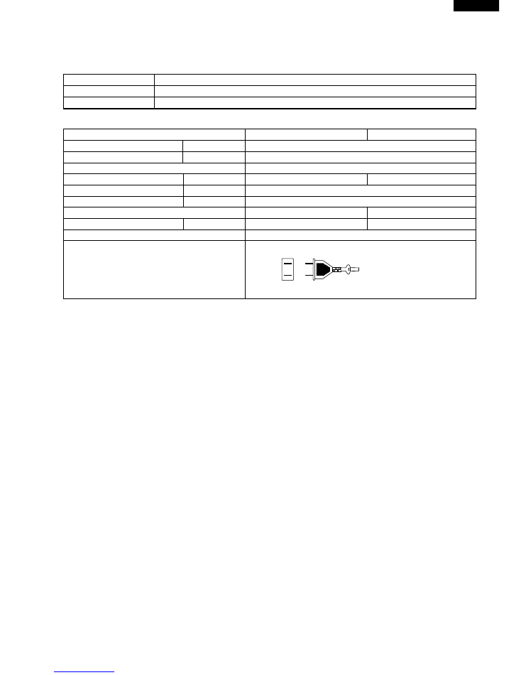
COLOR
Items
SJ-V35L-GY, SJ-V39L-GY
Outside color
Gray
Inside color
White
Source cord
2pin
Plug type
A-1
4
SJ-V35L
SJ-V39L
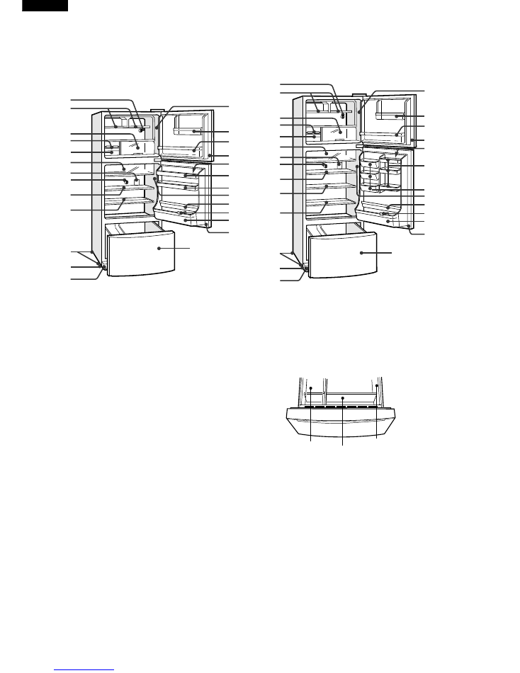
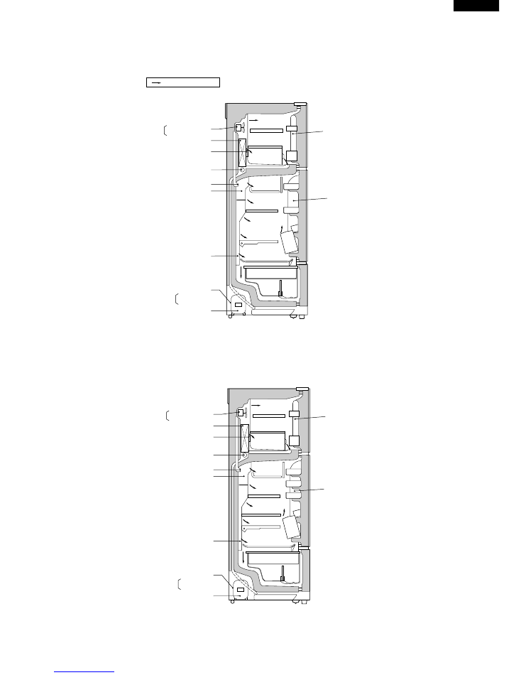
DESIGNATION OF VARIOUS PARTS
1. Freezer temp. control knob
2. Freezer shelf (Free case)
3. Freezing room
4. Ice cube maker
5. Ice cube box (Ice storage box)
6. Chilled case
7. Light (Lamp)
8. Refrigerator temp. control knob
9. Refrigerator shelf (S) (Refrigerator tray)
10. Refrigerator shelf (L) (Refrigerator tray L)
11. Three position adjustable shelf (Free set shelf)
12. Caster
13. Adjustable feet (Adjustable leg)
14. Evaporating pan & Evaporating pan cover
15. Fan switch
16. Freezer pocket (S) (F-door pocket S HS)
17. Freezer pocket (L) (F-door pocket L HS)
18. Magnetic door seal (Door packing)
19. Egg holder (S) (Egg tray)
20. Egg holder (L) (Egg tray)
21. Egg pocket (Door pocket HS)
22. Utility pocket (Door pocket HS)
23. Utility pocket (Door pocket S HS)
24. Small pocket (Dressing pocket)
25. Fan & light switch
26. Bottle pocket (S) (Bottle pocket S)
27. Bottle holder (Bottle guard)
28. Bottle pocket (L) (Bottle pocket HS)
The names in parenthesis are the denominations used in the REPLACEMENT PARTS LIST.
EXTERNAL DESCRIPTION
1
2
3
4
5
6
7
8
9
11
12
13
14
15
16
17
18
19,20
21
22
25
26
27
28
18
29
SJ-V35L
SJ-V39L
1
2
3
4
5
6
7
8
9
12
13
14
15
16
17
18
20
23
24
25
26
27
28
18
29
11
10
29. Vegetable compartment
Vegetable case
Parting plate
(Bottle guard)
Fruit case
5
SJ-V35L
SJ-V39L
CONSTRUCTIONS
Figure D-1 (SJ-V35L)
Fan motor (Left)
F-thermostat (Right)
Evaporator
Defrost thermostat
Defrost heater
Damper thermostat
R-C box
Multi louver
Protect cover
Starting relay
Overload relay
Compressor
Door switch 2P
Door switch 3P
Mark; Cold air flow
Figure D-2 (SJ-V39L)
Fan motor (Left)
F-thermostat (Right)
Evaporator
Defrost thermostat
Defrost heater
Damper thermostat
R-C box
Multi louver
Protect cover
Starting relay
Overload relay
Compressor
Door switch 2P
Door switch 3P
6
SJ-V35L
SJ-V39L
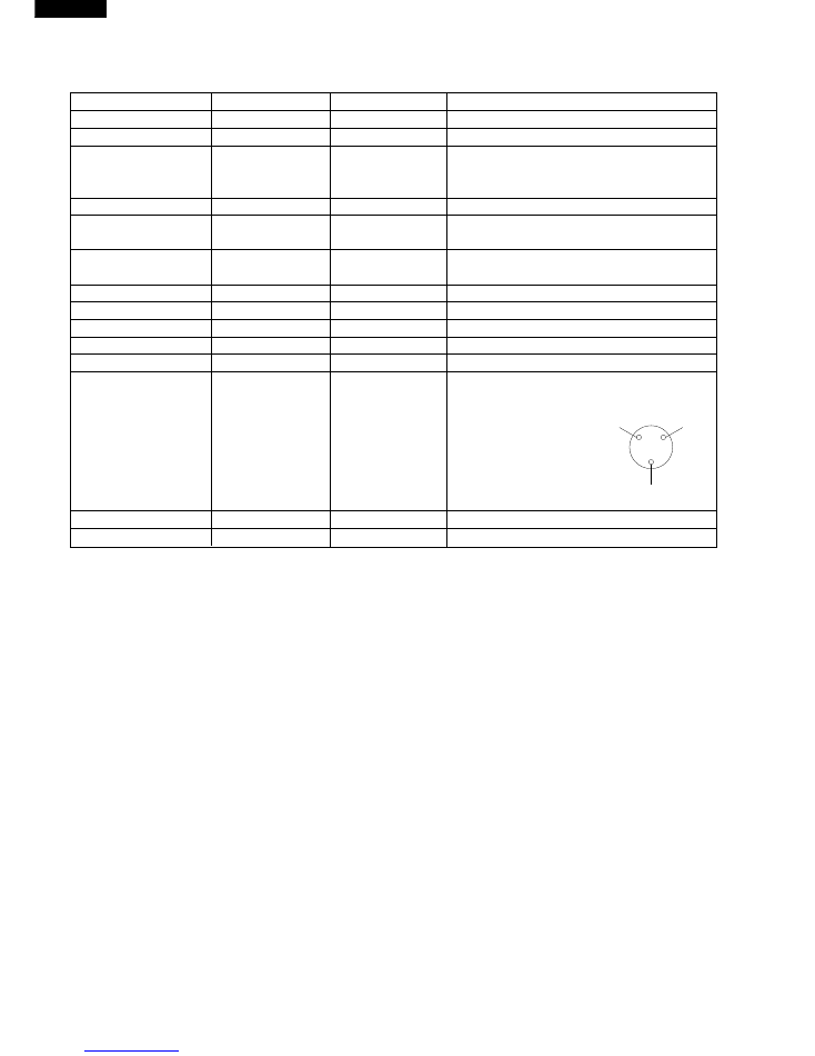
LIST OF ELECTRICAL PARTS
ITEMS
TYPE NAME
RATING
SPECIFICATIONS
Damper thermostat
MM1-6129
Open : 0.5˚C , Close : -4˚C
Defrost thermostat
US602S
250V,8A
Open : 10˚C , Close : 1˚C
Timer
ND0804M2PR
200-240V
Integration type
50/ 60Hz
Cycle time : 8h43m(50Hz)
Delay time : 4m50s(50Hz)
Thermo. fuse (defrost)
SF70E
250V,10A
Cut off temperature : 72˚C
Door switch
PS100-01T
250V,0.5A
2 terminals type push-button
(Freezer compartment)
Door switch
PS100-T
250V,0.5A
3 terminals type push-button
(Refrigerator compartment)
Fan motor
3R00044B
220/240V,50Hz
Lamp
—
240V,10W
E-12
Lamp socket
—
250V,1A
E-12 (Hard plastic body type)
F-thermostat
MM1-8038
ON : -20˚C , OFF : -25˚C
Defrost heater
MM1-4021
220/230/240V
378
Ω
with deodorizer
Compressor
FL1568SZ
220/230/240V
50Hz
Main : 13.3
Ω
Terminal shape
Aux : 25.6
Ω
Cooling capacity 188W
Starting relay
PETOSAT
300V
22
Ω
Protector
2.0C36A1
—
130˚C / 60˚C
Common
Main coil
Aux. coil
7
SJ-V35L
SJ-V39L
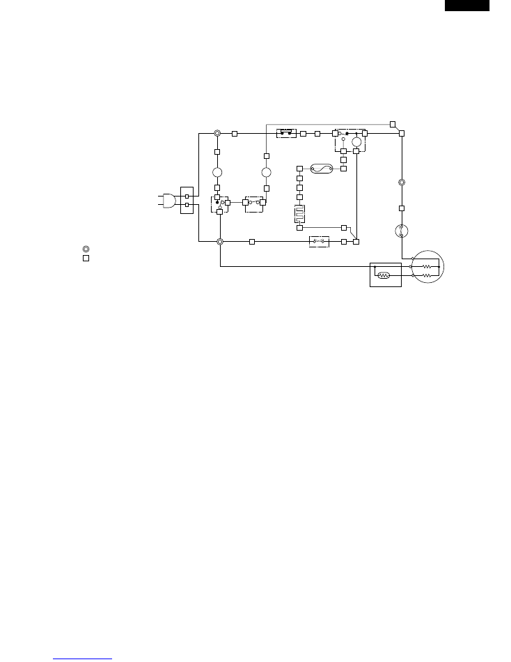
WIRING DIAGRAM
Be sure to replace the electrical parts with specified ones for maintaining the safety and performance of the set.
L
FM
TM
C
M
A
Compressor
Starting Relay
(B)
(B)
(P)
(P)
(W)
Defrost
Thermo.
(P)
R Door
Switch
F Door
Switch
(O)
(S-B)
Lamp
Fan
Motor
(Br)
(Br)
F-Thermostat
(R)
(W)
Thermo.
Fuse
(Bk)
Defrost
Heater
Defrost
Timer
Protector
CONNECTED IN TERMINAL BOX
CONNECTOR
Plug/
Cord
2
3
1
B
Bk
Br
G
O
S-B
P
R
W
Y
:BLUE
:BLACK
:BROWN
:GRAY
:ORANGE
:SKY-BLUE
:PINK
:RED
:WHITE
:YELLOW
1
2
3
4
1
2
(B)
(G)
Figure W-1. Wiring Diagram
8
SJ-V35L
SJ-V39L
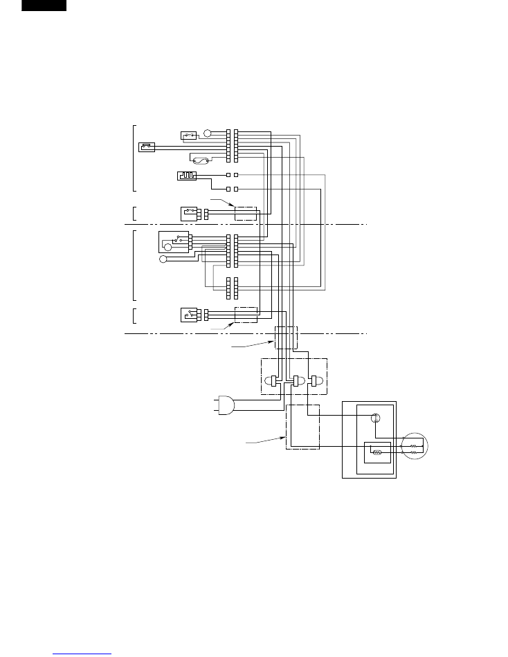
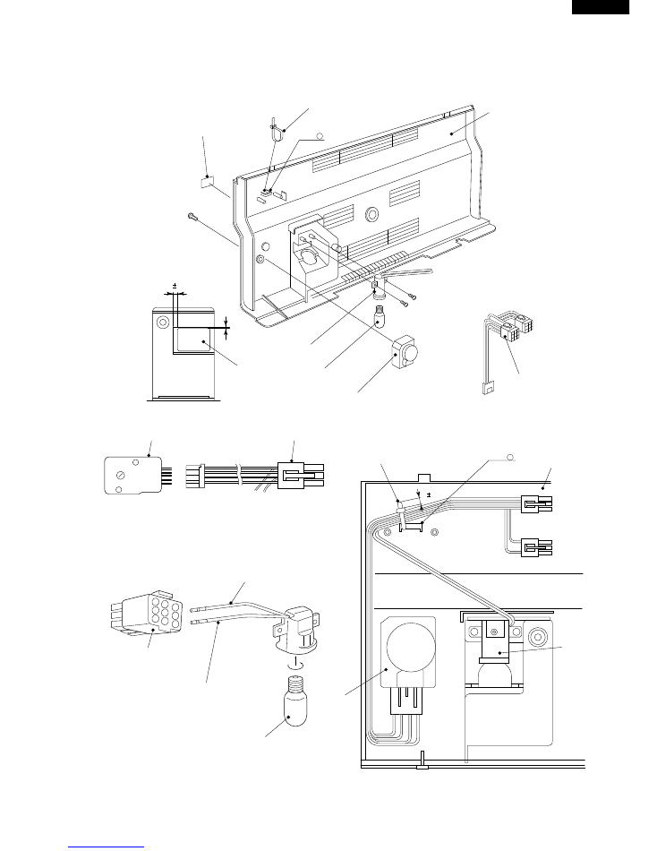
Figure W-2. Electric Accessories Layout
1
2
3
4
5
6
7
8
9
1
2
3
4
5
6
7
8
9
O-1
G-1
P-1
B-1
Br-1
R-1
Bk-1
W-1
C1 ( LR-09-1V )
FM
Fan
Motor
Defrost
Thermo.
F-Thermostat
Thermo.
Fuse
Defrost
Heater
1
2
3
4
5
6
7
8
9
1
2
3
4
5
6
7
8
9
1
2
3
4
5
6
1
2
3
4
5
6
1
2
3
1
2
3
3
2
4
1
TM
L
Defrost
Timer
Compressor
C
M
A
Starting relay
F Door
Switch
C2 (3P-110V)
C6 (SGF-21T-5)
W-2
C7 (SGF-21T-5)
W-3
1
1
Protector
Terminal cover
Plug/Cord
Tube
Tube
Tube
2
2
P-2
O-1
R-1
Bk-1
G-2
P-1
S-B-1
Br-2
G-1
W-2
C3 (LR-09-1V)
C5 (LR-06-1V)
W-2
1
2
3
R Door
Switch
C4 (3P-110V)
B-2
P-2
1
2
3
S-B-1
Tube
CE-2
(Br)
CE-2
(B)
CE-2
(G)
FREEZER
REFRIGERATOR
MACHINE ROOM
(Food liner)
(RC-box ass’y)
(Food liner)
(E.V cover ass’y)
Lamp
TERMINAL BOX
W-3
9
SJ-V35L
SJ-V39L
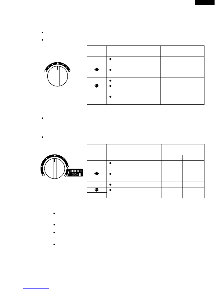
1. ADJUSTABLE TEMPERATURE CONTROL
(1) Temperature control of freezer
Thermostat (senses freezer temperature) operates on ON/OFF switchover to control the compressor and
allows the freezer temperature to keep at a suitable temperature.
However adjust the freezer temp. control knob as follows depending upon the storing condition of foods.
Figure F-1.
(2) Temperature control of refrigerator
Damper-thermostat senses temperature of the refrigerator and changes the opening angle of the damper
automatically.
However, as the Damper-thermostat has no function to switch on or off the compressor and cool air
circulating fan, the freezer temperature control causes temperature in the refrigerator to vary to some
extent.
However, adjust the refrigerator temp. control knob as follows depending upon the cooling condition.
Figure F-2.
NOTE:
The refrigerator temperature is affected also by the freezer temperature. If the freezer temp.
control knob is set at the position "MAX", the temperature tends to be lower than the following
values, and if set at near the position "MIN", temperature tends to be higher.
If the refrigerator is operated for a long time with the freezer temperature control sets the "MAX"
position, foods stored in the refrigerator compartment may also freeze.
When refrigerator temperature control sets to the "CHILLED ZONE", some foods stored may
freeze.
In this case adjust control set back to the "MED" position.
When refrigerator temperature control sets to the "CHILLED ZONE", some foods stored in fresh
cases may also become frozen.
The values shown above refer to the measurement carried out center area and 1/3 of overall height from the bottom
at each of the refrigerator and the freezer after machine has been operated at an ambient temperature of 30˚C with no
food stored and the door closed until the temperature is stabilized.
The values vary depending upon frequency of opening and closing the door, ambient temperature, amount of stored
foods and manner of storing foods.
FUNCTIONS
MIN
MED
MAX
FREEZER TEMP. CONTROL
Coldest
KNOB
SETTING
MAX(Coldest)
MIN
PURPOSE
For making ice rapidly or fast
freezing.
For storing frozen food for a
short period (up to one month).
When frozen food or ice cream
is not stored.
For normal freezing.
MED
When restocking with fresh
food.
VALUE OF
TEMPERATURE
Approx. -21˚C
Approx. -18˚C
Approx. -15˚C
KNOB
SETTING
MED
CHILLED
ZONE
(Coldest)
MIN
PURPOSE
For keeping freshness of
food longer.
For normal operation.
When the refrigerator provides
excessive cooling.
When the refrigerator does
not provide sufficient cooling.
VALUE OF
TEMPERATURE
refrigerator
chilled room
Approx.
0˚C
Approx.
-3˚C
Approx.
6˚C
Approx.
4˚C
Approx. 3˚C Approx. 1˚C
The values shown above refer to the case where the freezer temp. control
knob is set at "MED".
Coldest
MIN
MED
CHILLED
ZONE
REFRIGERATOR TEMP. CONTROL
10
SJ-V35L
SJ-V39L
2. DEFROSTING
(1) No defrosting operation is necessary
No defrosting operation is necessary.
As this machine is so designed that a built-in
evaporator cools air and a fan circulates cooled
air, neither the freezer nor the refrigerator is
frosted, though the evaporator is frosted.
The frosted evaporator is defrosted automatically
due to the function of defrosting timer and heater,
requiring no defrosting operation.
(2) Where is melted frost brought
1. Melted frost is brought into the evaporating
pan at the bottom of the set and is evaporated
here by the heat of sub condenser.
2. Be sure to use the evaporating pan as inserted
so as to be level with the outer case.
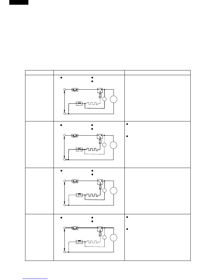
(3) The following circuit diagrams in the table show automatic defrosting function of the refrigerator with
timer and defrost thermostat.
Operation
Electric diagram
Description
1. Cooling
(Normal)
2. Defrosting
(Time 20 to 30 min.)
3. Drain
(Time approx. 5 min.)
4. Cooling (start)
The integration timer integrates running
time of the compressor. When it reaches
cycle time of defrost timer, the timer
contact is changed to start defrosting.
When the defrost thermostat becomes
OFF, the timer motor at rest starts running.
During the operation time (delay time of
defrost timer), defrosted water is drained
outside the refrigerator.
Timer contact is changed to cooling
operation and the compressor starts
running and the timer motor stops.
Defrost thermostat contact becomes ON
when it’s cooled. And the timer moter
starts running. (Figure F-4.)
Figure F-4.
Figure F-5 .
Figure F-6.
Figure F-7.
TM
COMP
Defrost thermostat ON
Compressor running
Timer motor running
Timer contact
Defrost
thermostat (ON)
Compressor
Timer motor
SOURCE
TM
COMP
Defrost thermostat OFF
Compressor running
Timer motor running
Thermostat
Timer contact
Defrost
thermostat (OFF)
Compressor
Timer motor
SOURCE
TM
COMP
Defrost thermostat OFF
Compressor stops
Timer motor running
Thermostat
Timer contact
Defrost
thermostat (OFF)
Compressor
Timer motor
SOURCE
TM
COMP
Defrost thermostat ON
Compressor stops
Timer motor stops
Thermostat
Timer contact
Defrost
thermostat (ON)
Compressor
Timer motor
SOURCE
Thermostat
The timer contact is changed to start
defrosting, the timer motor stops, and
power is supplied to the defrost heater.
It takes about 20 to 30 min. to defrost.
When little frosted the defrosting takes
little time. When much frosted, the
defrosting takes much time.
Defrost heater
Thermo. fuse
Defrost heater
Thermo. fuse
Defrost heater
Thermo. fuse
Defrost heater
Thermo. fuse
11
SJ-V35L
SJ-V39L
(4) As a reference to determine the causes of trouble, malfunction and phenomena are described below.
Refer to the following when repairing.
1. Disconnection of defrost heater
As off-cycle defrosting is performed, the defrosting time is extremely prolonged. Each time defrosting is
started, the freezer temperature rises and a portion of ice and stored foods are melted.
2. Melted thermo. fuse or opened-circuit due to the defect of defrost thermostat.
When the above mentioned trouble occurs in cooling operation, the timer motor does not run, defrosting
will not take place, and consequently freezing is caused. In the above mentioned condition, when the timer
shaft is turned by hand to defrost, the timer motor runs during the operation time. However, the motor stops
from the time when the contact is changed, and freezing causes.
NOTE:
As the thermo. fuse assembly is intended to prevent dangers, do not use it under shorted condition even
for a short period.
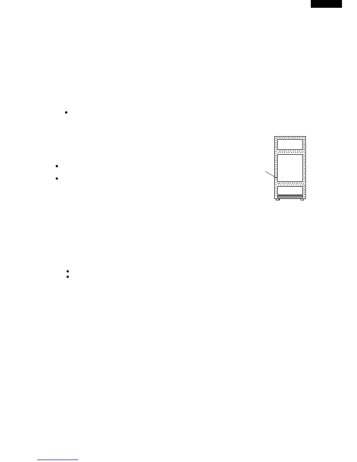
3. DEW PREVENTION
The hot pipe, namely D.P.-condenser, is arranged around the flange part
of cabinet and the C-partition plate, preventing dew from being generated
on the cabinet.
NOTE:
D.P.-condenser pipe may be felt hot if touched by hand while the
compressor is in operation.
If you are asked about this, please explain that the hot pipe serve to
prevent the dew generation.
Figure F-8.
4. INSPECTION OF INITIAL STARTING
(1) Inspection of cooling unit
1. Set the temperature control knob to "MAX" and check that the compressor starts to operate.
2. Depress the door switch to run the fan and check that cool air is blown out of the cold air outlet of the
freezer and
the refrigerator.
3. When the compressor does not work, check that the timer is not set to "defrost" position.
4
It takes about two or three hours to put food in the refrigerator after starting operation.
NOTE:
Return the temperature control knob to "MED" position afterward.
When the refrigerator is operated initially after installed, the compressor may vibrate excessively for 1 to 2
min.
However, vibration becomes normal if it is continuously operated.
(2) Inspection of defrost device
Operate the refrigerator for 20 to 30 min. and then check the defrost device in the following procedures :
Allow 5 min. to restart the compressor since immediate starting after stopping will cause unsmooth operation.
1. Turn the timer shaft clockwise with a screw driver.
At this time, make certains the timer clinks and the compressor stops.
2. After more than 5 min., turn the shaft further to operate.
Make certain cooling operation is started again.
Hot pipe
12
SJ-V35L
SJ-V39L
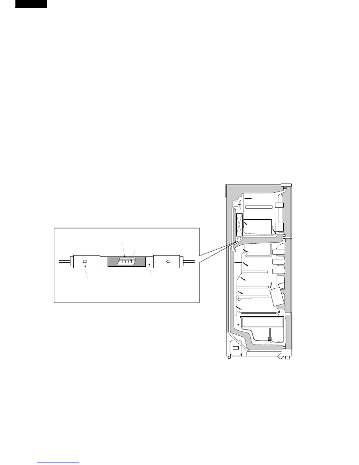
DEODORIZING OPERATION
Deodorization is performed with the aid of a deodorizing heater which uses a conventional glass pipe heater having a
deodorizing function.
1. Operation
The deodorizing system is arranged in the cool air passage, so that deodorization effect is always maintained.
Therefore, any operation is not necessary.
2. Component Parts and Deodorizing Principle
(1) This deodorizing heater uses the porous catalyst layer laid on the surface of radiant heater glass pipe (high-
quality quartz glass). The deodorizing catalyst consists of zeolite, alumina, silica, noble metal, and rare-earth
oxide. It adsorbs and decomposes the following odors.
It adsorbs:
Stench odor evolved from vegetables and fruits ... Methyl mercaptan,
Stench odor evolved from meats and fishes ... Trimethylamine,
Stench odor evolved from fermentation foods ... Aliphatic acids.
The noble metal and rare-earth oxides act as catalysts which oxidize and remove the adsorbed stench
ingredients at a temperature of over 250˚C.
(2) In normal cool state, this deodorizing heater adsorbs the stench ingredients. In defrosting state where the
heater is heated, it oxidizes and removes the adsorbed stench ingredients by a catalysis.
Silicon cap
Quartz glass pipe
Heater lead
Deodorizing catalyst layer
(Structure)
13
SJ-V35L
SJ-V39L
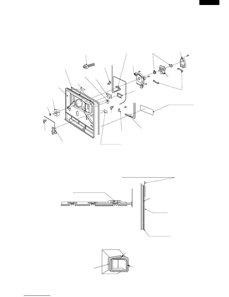
ASSEMBLING PROCEDURES OF MAIN PARTS AND CAUTIONS
CAUTION: DISCONNECT THE UNIT FROM THE POWER SUPPLY BEFORE ANY REPAIRING.
1. E.V COVER ASSEMBLY
Datam line:End of corner radius
E.V cover sealer A
Tip of rib
Start (End)
10mm
Paper tape (width:20mm)
Seal the slit with paper tape (3points)
(1) Sticking of E.V cover sealer A, B
Lead E.V.cover ass’y
Fan motor holder B
Motor cushion
Motor cushion
Fan motor
Fan motor
holder A
Dofrost thermo. ass’y
L-band C
E.V.cover
sealer C
E.V.cover
sealer D
E.V.cover sealer A
Paper tape
E.V.cover
E.V.cover sealer B
Aluminum tape
L-band C
Paper tape
Thermo. fuse ass’y
SL-5N clip
Propeller fan 100
Fan clamp
L-band C
F-thermostat
Datum line : Tip of rib
Overlap
E.V cover sealer B
14
SJ-V35L
SJ-V39L
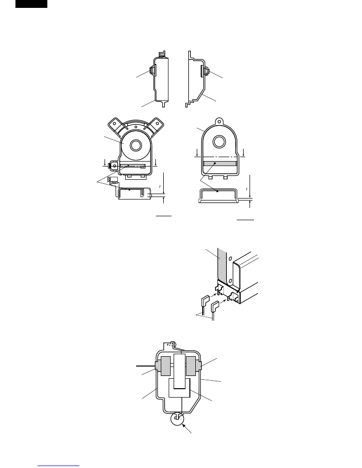
(2) Fixing of Fan motor
Motor cushion
Fan motor cushion B
Motor cushion
Fan motor cushion A
C
C
Fan motor
cushion A
Sec CC
Motor
cushion
-2 2 mm
-2 2 mm
Fan motor
cushion B
D
D
Motor
cushion
Sec DD
Motor cushion
Motor cushion
Fan motor cushion A
Fan motor cushion B
Fan motor
Check claw is surely fixed
to the hole of Fan motor cushion.
Fan motor
Lead wire
Insert terminal of Lead wire "Orange"
and "Gray" to the terminal of Fan motor.
Lead ev-cover ass’y has positive lock.
15
SJ-V35L
SJ-V39L
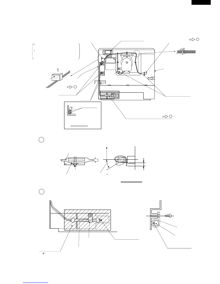
(3) Wiring of Lead wire
E.V cover saler C
E.V cover sealer D
E.V cover
Detail
Fix with L-BAND C
Fixing of Defrost thermo. ass’y
Fixing of Thermo. fuse ass’y
Sec C - C
Lead wire
Claw
Up side
E.V cover
sealer D
Claw
Paper tape
Seal the hole
C
C
Detail
Stick on lead wire
Hold lead wire with pin
(5 points)
Fixing of
F- thermostat
Defrost thermo ass’y
L-band C
Thermo sensing element side
Horizontally
E
No good
Within 30
Cut off to 7mm or shorter
View from E
SL-5Nclip
Thermo. fuse ass’y
Lead wire "WHITE"
Lead wire "WHITE"
SL-5Nclip
Thermo. fuse ass’y
Aluminum tape
(50 m X 70mm X 130mm)
Take out lead wire from square hole to
front, and seal with E.V. cover sealer D.
Set lead wire at right side of the
hole. (See from rear)
But only lead wire from
Thermo. fuse ass’y is set under
side of the hole.
B Fixing of thermo. fuse ass'y
A Fixing of Defrost thermo. ass'y
B
A
C
16
SJ-V35L
SJ-V39L
20 _ 5mm
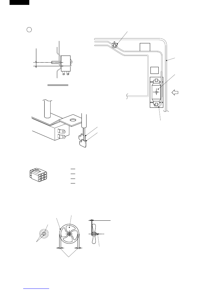
C Fixing of F-thermostat
Forming of capillary tube
View from F
L-band C
E . V cover
F
Lead wire
Lead wire RED
Lead wire BLUE
F-thermostat
+
(4) Wiring of Connector
(5) Fixing of Fan
Set Fan clamp to Propeller fan 100 and insert it to the shaft of Fan motor.
E .V cover
Propeller fan 100
More than 3mm
Shaft
-1~1mm
Slit of each Fan clamp and Propeller fan should not be at same position.
Fan clamp
Slit
1
4
7
2
5
8
3
6
9
No. 3 Pink lead of Defrost thermo. ass’y
No. 4 Blue lead of Defrost thermo. ass’y
No. 7 Black lead of Thermo. fuse ass’y
No. 8 White lead of Thermo. fuse ass’y
17
SJ-V35L
SJ-V39L
2. R-CBOX COVER ASSEMBLY
Defrost timer
D timer lead ass’y
connect
"SKY-BLUE" inserted in No.5
"BROWN" inserted in No.6
D timer lead ass’y
1
2
3
4
5
6
7
8
9
Lamp
5 2mm
Nylon band
rib a
R-C box cover
screw
Lamp
socket
Defrost
timer
Nylon band
rib a
Warning label
R-C box cover
1mm
Warning label
Lamp socket
Lamp
Defrost timer
D timer lead ass’y
WARNING
5 2mm
18
SJ-V35L
SJ-V39L
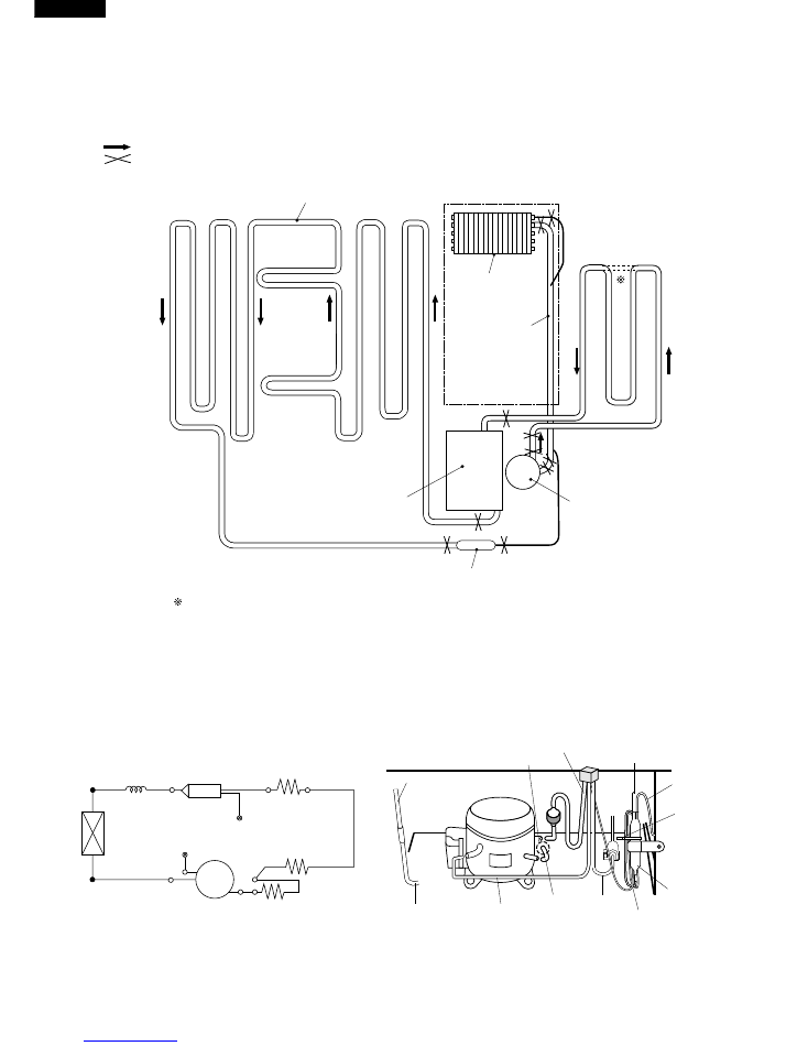
COOLING UNIT
Mark : Refrigerant flow
Mark : Brazing portion
Inner condenser
Evaporator
Suction pipe
Compressor
Capillary tube
Dryer
Sub condenser
Only for SJ-V35L
Back condenser
Figure C-1.
Figure C-3.
Figure C-2.
Cooling unit
Location
Capillary tube
Dryer
Charge pipe
Charge pipe L
Suction pipe
Evaporator
Compressor
Back condenser
Sub. condenser ass’y
Hot pipe
Dryer
Hot pipe
(outlet)
Charge pipe L
Charge pipe
Capillary tube
Sub condenser
Back condenser
Pinch point
Hot pipe (inlet)
Nylon band
Sub condenser
Suction pipe