Full Text Searchable PDF User Manual
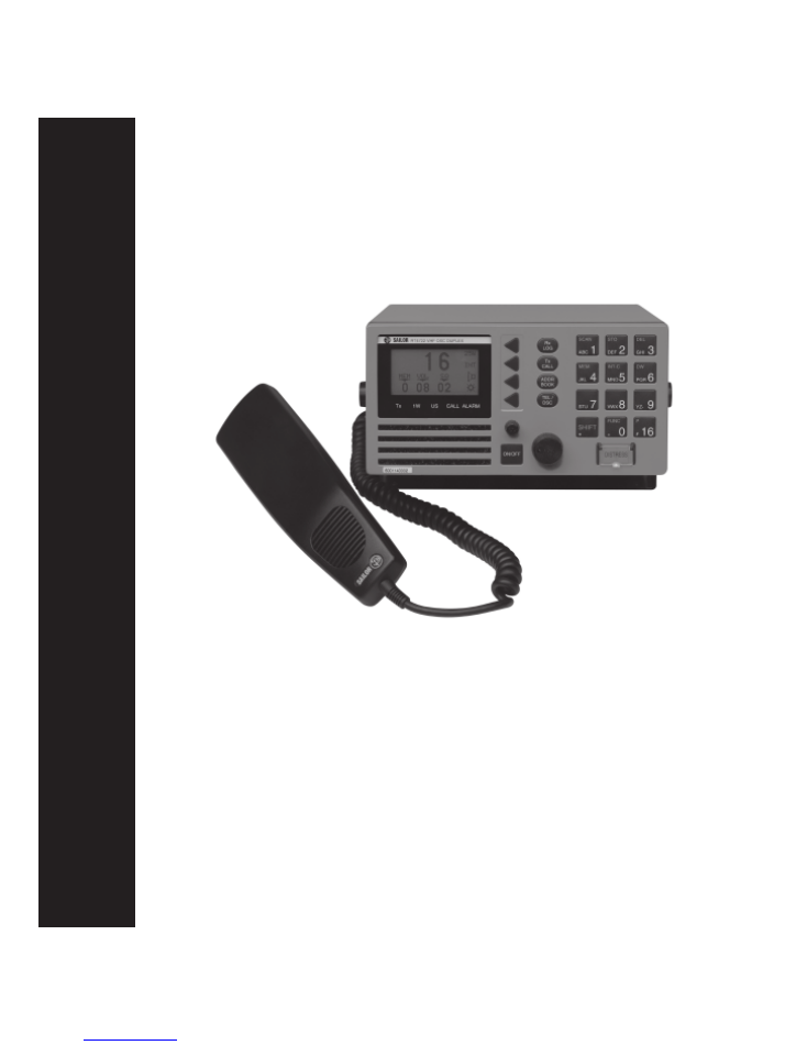
SAILOR
RT4722
VHF-DSC DUPLEX
Installation Manual

Introduction
S. P. Radio A/S
For more than half a century S. P. Radio A/S has been the market
leader within maritime radio communication.
SAILOR
The communication products and systems of S. P. Radio are
recognized under the brand name SAILOR. The Sailor name has
become a guarantee of reliable and technologically superior radio
equipment, ranging from basic VHF units to satellite systems and
complete compact GMDSS solutions.
Products
The SAILOR COMPACT 2000 GMDSS is based on the well proven
range of Sailor products specifically developed to meet the GMDSS
requirements and supported by a world-wide Certified GMDSS
service concept, giving several hundred reasons for shipping
companies to choose equipment manufactured by S. P. Radio A/S.
Today S. P. Radio A/S is recognized as the world’s leading supplier
of GMDSS solutions.
The SAILOR COMPACT 2000 GMDSS has already been and still is
constantly supplied to a large number of the world’s leading shipping
companies and national naval fleets. It is a complete GMDSS
solution which matches communication and safety needs exactly -
regardless of whether you operate with A1, A2, A3 or A4.
The System 4000 GMDSS sets new standards. It is constructed on
the basis of our comprehensive experience developing GMDSS
equipment. It satisfies all the relevant requirements regarding safety
and efficiency. The System 4000 presents a large number of
attractive convenience and safety facilities, either as a complete
solution or as a series of stand-alone products.
Sailor has a long history as a satellite communications supplier
offering a full programme of satellite systems which includes Mini M,
SAT-C and a number of stationary satellite systems. Our SAT-B is a
breakthrough in maritime aerial technology and reliability. The SAT-B
is the best possible choice when high quality speech transmission,
top level security and the capacity to deal with large volumes of
telex, fax, data and high-speed data (HSD) transmissions are required.
Training certification
Training of deck officers to meet the requirements within the concept
of GMDSS, as to operation of equipment and basic understanding of
the systems, is an extremely important factor for the overall success-
ful implementation of GMDSS. As a unique initiative for GMDSS
solutions, we can supply a complete software training programme for
on-board training, to be used as preparation in order to fulfil the
GMDSS requirements for obtaining the
General Operation Certificate.
Service
A world-wide Sailor GMDSS certified service concept has been
established in order to provide the shipping industry with a highly
professional and uniform level of service. The Sailor GMDSS
Certified Servide Centre concept, which is constantly monitored,
ensures that replacement units and spare parts are available at all
the Sailor Certified Service Centres around the world. Service
centres which are in position along all the major shipping routes.
Furthermore the Certified Service Centres ensure that technicians
with an annually updated training are ready to provide service 24
hours a day, 365 days a year.
Maintenance
Because of the fact that GMDSS equipment has been installed on
board ships in order to meet the SOLAS (Safety of Life At Sea)
convention, manufacturers and suppliers of GMDSS equipment have
a certain responsibility to secure reliable supplies of equipment and
spares in the years to come.
Therefore shipowners operating ships both locally and internationally
should be fully aware of the importance of fitting GMDSS solutions
which will be fully supported by the manufacturer.
It is a firm policy of S. P. Radio A/S, as the world’s major manufac-
turer and supplier of GMDSS solutions, that for both the present
GMDSS solutions and for future, alternative product solutions, all
Sailor GMDSS systems will be entering the next century, in fully
parallel production.
Please note
Any responsibility or liability for loss or damage in connection with
the use of this product and the accompanying documentation is
disclaimed.
The information in this manual is furnished for informational use only,
is subject to change without notice, may contain errors or inaccura-
cies, and represents no commitment whatsoever.
This agreement is governed by the laws of Denmark.
Doc. No.: M4722GB0
Issue: B/9945

1
RT4722
Contents
1
Technical Specification ..................................................................................................................................... 2
2
Installation .......................................................................................................................................................... 4
2.1
Mounting Possibilities ........................................................................................................................................... 4
2.2
Power Supply ....................................................................................................................................................... 7
2.3
Aerial .................................................................................................................................................................... 7
2.3.1 Placing the Aerials ................................................................................................................................................ 8
2.4
Handset Connection ............................................................................................................................................. 8
2.5
Loudspeaker Connection ..................................................................................................................................... 9
2.6
Connectors ........................................................................................................................................................... 9
2.6.1 SPARC-Bus Cable ............................................................................................................................................... 10
2.6.2 Options Connector H4992 ................................................................................................................................... 11
2.7
Cable Length ........................................................................................................................................................ 12
2.7.1 Power Cable ......................................................................................................................................................... 12
2.8
Electrical Connections .......................................................................................................................................... 12
2.8.1 Power Connectors ................................................................................................................................................ 12
2.8.2 Interconnection Cable Specification For VHF Printer Connection ...................................................................... 13
2.9
Compass Safety Distance .................................................................................................................................... 13
2.10
Test Procedure TX/RX DSC Call ......................................................................................................................... 14

2
Technical Specification
RT4722
1
Technical Specification
Conforms to all relevant international requirements and resolutions as agreed by ETSI, IEC, ITU, and IMO as well as
other national requirements. These specifications include ETS 300 162, ETS 300 338, IEC 945, IEC 1097-3 and IEC
1097-7.
General information
Normal channels
All int. ch’s for 25 kHz operation.
Up to 40 private channels.
Opt. channels
All int. ch’s for 12.5 kHz operation.
Up to 224 ch’s with up to 54 private ch’s.
Channel spacing
25 kHz / opt. 12.5 kHz
Frequency range
Rx/Tx:
150.800 MHz - 157.425 MHz.
Rx:
160.625 MHz - 163.6 MHz.
Operating modes
Simplex/Semi-duplex/duplex.
Modulation
G3EJN for telephony receiver
G2B for DSC signaling
Frequency stability
±10 ppm/ opt. ± 5 ppm
Aerial connectors
Standard 50 ohm female, SO239
Temperature range
-15° C to +55° C
Supply voltage
13.2V DC Nominal
Supply range
10.8V DC to 15.6V DC
Supply current
Stand-by
0.14A
Transmitter on 1.5A (Low power)
Transmitter on 6.5A (High power)
Transceiver dimen.
H*W*D
100*200*259mm.
Transceiver weight
3.9 kg
Receiver
Sensitivity for:
12 dB SINAD
-118 dBm or 0.28 µV p.d.
AF rated power
Output 1
4W/ 4
Ω
Output 2
6W/ 4
Ω
Distortion THD
Below 5%
Signal/noise ratio
Better than 40 dB
AF response
- 6 dB/octave
Spurious emission
Below 2 nW
Spurious resp. att.
More than 70 dB
9945

3
Technical Specification
RT4722
Duplex spurious resp. att.
More than 70 dB
Duplex desensitation
Below 3 dB
Intermodulation att.
More than 68 dB
Co-channel rejection
Better than -10 dB
Adj. ch. selectivity
More than 70 dB
Blocking
More than 90 dBµV
Transmitter
RF output power *
High 25W + 0 dB to -0.5 dB
Low
0.9W +0.5 dB to - 1 dB
Adj. ch. power
Below -70 dBc
Spurious radiation
Below 0.25 µW
Cabinet radiation
Below 0.25 µW
AF response
+ 6 dB/octave
Distortion
Below 5%
Signal/noise ratio
Better than 40 dB
DSC Facilities:
DSC operation
According to Rec. ITU-R M.541-6
and Rec. ITU-R M.689-2
DSC protocol
According to Rec. ITU-R M.493-7 class A
Navigator interface
NMEA 0183, GGA,GLL,ZDA
NMEA input current 8mA type
Symbol error rate
below 1*10
-2
at
-119 dBm or 0.25 µV p.d.
Modulation
1700 Hz ± 400 Hz
1200 baud ± 30 ppm
Frequency error
Below ± 1 Hz
Residual DSC-mod.
Below - 26 dB
* Note:
The transmitter has a built in temperature sense function that will reduce the output power from 25W to
1W if the radio is getting too hot. This may happen if there is no free air circulation around the radio.
9945
4
Installation
RT4722
2
Installation
2.1
Mounting Possibilities
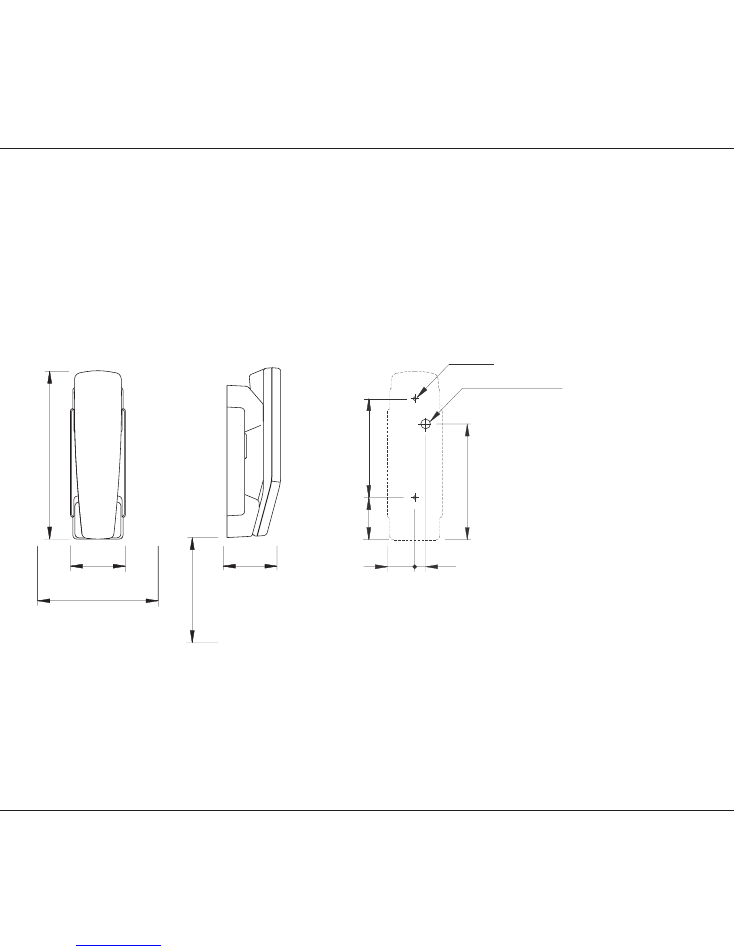
Mounting possibilities, dimensions and drilling plan
Handset
Drilling Plan
4-0-35999
68.5
66.5
209
min. 300
Space for handset access
min. 200
Space for cable and
handset cable
4-0-35556
34
123
52.5
2 x ø4.5
ø12 for cable entry
144
13.5
Weight:
Handset
0.4 kg
5
Installation
RT4722
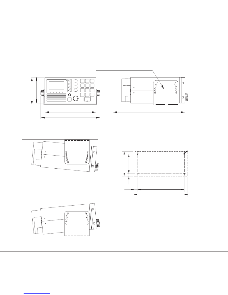
VHF-DSC DUPLEX With Mounting Bracket
36846
200.00
231.00
100.00
110.00
max. 280
Bracket (Standard)
Mounting Option
Drilling plan
36847
Tilting +/-6 °
4 x ø4
14.25
11.00
76.50
98.50
209.00
180.50
Weight:
VHF-DSC DUPLEX
3.9 kg
Mounting Bracket
0.7 kg
6
Installation
RT4722
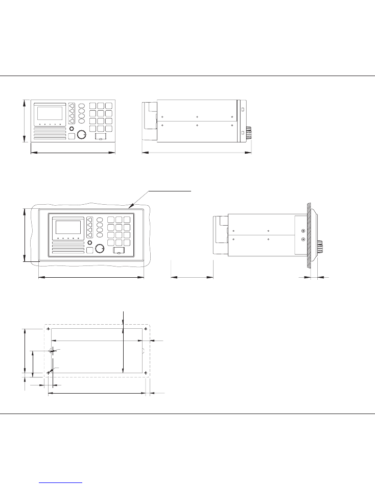
VHF-DSC DUPLEX
36848
200.00
100.00
259.00
VHF-DSC DUPLEX With Mounting Bracket MB4994 (Flush mounting)
Bracket (Option)
36849
250.00
125.00
Space for Cable entry
min. 100.00
16.00
Drilling Plan
4-0-36006
62.50
4 x M4
230.00
10.00
R7.00 Make a cut for
handset cable entry
104.00
10.50
215.00
105.00
20.00
17.50
10.00
Weight:
Mounting Bracket MB4994
(Part no. 80499410)
0.2 kg
WARNING:
Only use original screws; otherwise you risk short-
circuiting the battery ground to the ship ground.
9945
7
Installation
RT4722
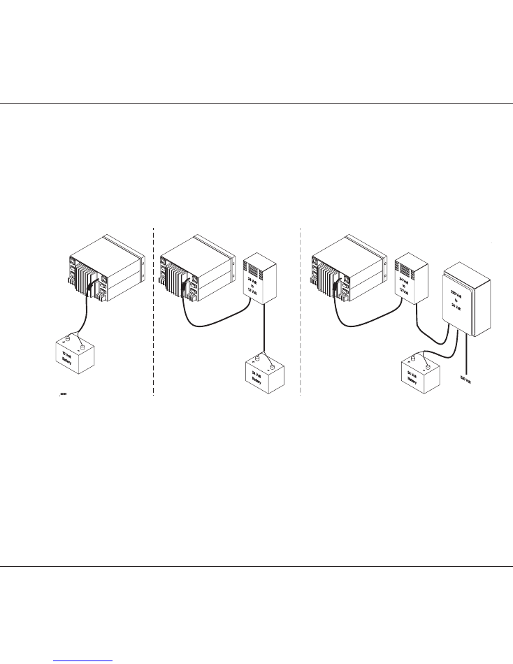
2.2
Power Supply
The standard power supply for the VHF unit is 12V DC.
For 24V DC supply an external power supply with the type number N420 can be used. The N420 is in
principle a 24V DC to 13.2V DC serial regulator.
For 110V AC, 127V AC, 220V AC or 237V AC operation, an external power supply with the type number
N163S must be used together with N420.
Fuse
The fuse is a standard 10A mini car fuse. There is a spare fuse in the power cable connector.
2.3
Aerial
All common 50 ohm aerials which cover the used frequency range with a reasonable standing wave ratio, maximum
1.5, can be used.
The aerial is connected to the set by means of a 50 ohm coaxial cable with low loss, e.g. RG213U. At the cable end
a PL259 plug is mounted.
9945
8
Installation
RT4722
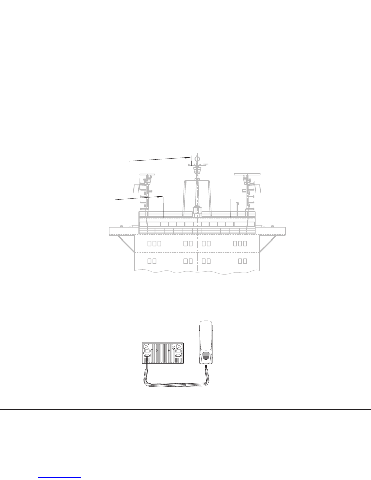
2.3.1
Placing the Aerials
In a GMDSS CLASS A installation, there are always two aerials. These should be mounted in a place that is as high
and clear as possible - as illustrated below. Note that the primary transceiver aerial must be placed at a higher level
than the channel 70 receiver aerial.
Channel 70
receiver aerial
transceiver aerial
37035
Primary
2.4
Handset Connection
The handset is connected directly to the HANDSET plug at the back of the VHF set.
35405
Rx
/
Tx
12V DC
SPARC-BUS
OPTION
PRINTER
HANDSET
9945
9
Installation
RT4722
2.5
Loudspeaker Connection
When one or more control units are connected to the VHF system, two of them can be set up to use the transceiver’s
two loudspeaker outputs to drive external speakers.
To link a loudspeaker to a control unit, enter the function menu and select external speaker:
Path: Func\general\sound\loudspeak\norm\alarm\extspk, and set external speaker to be 1 or 2 as desired.
The loudspeaker signals are available in the SPARC-bus cabling, and a loudspeaker can be connected to the system
in the handset hook parts or in the connection box.
Connect the loudspeaker cables to SPARC-bus signals (LS_1+ and LS_1-) or (LS_2+ and LS_2-) depending on which
speaker selection is made by the control unit(s).
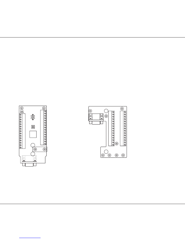
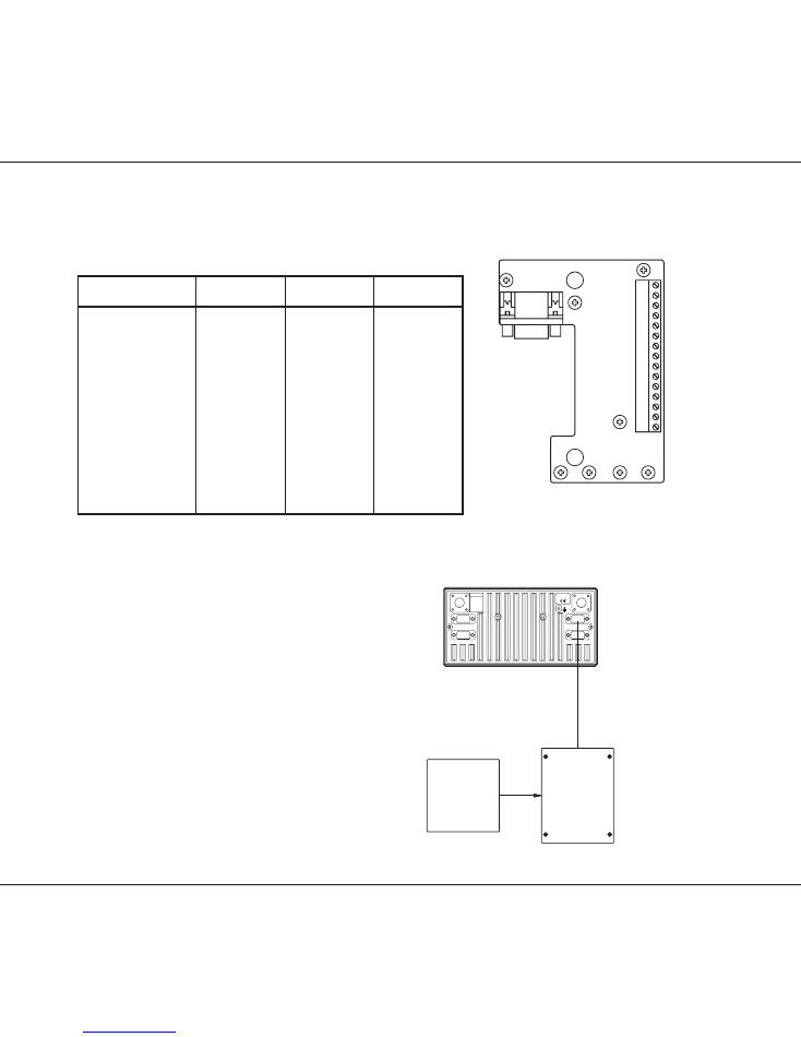
2.6
Connectors
Handset Hook
SPARC-Bus Connection Box H4991
35348
_ON
Term. ON
VDC
+12
LS_1-
LS_1+
LS_2+
LS_2-
-BAT
AF-
AF+
_AF-
RX
-BAT
_AF+
RX
SPARC+
_ON
SUPPLY
VDC
+12
RX_AF-
RX_AF+
+12VDC
-BAT
AF+
-BAT
AF-
SPARC-
LS_2+
LS_2-
_1+
LS
_1-
LS
SUPPLY
HOOK Connection 32262
SPARC+
SPARC-
+12VDC
X2
5
1
2
3
4
13
14
15
X3
6
7
8
10
11
9
S3
10
11
12
6
7
X1
8
9
R3
R2
R4
15
12
13
14
S1
R1
V1
V2
S2
3
4
5
1
2
35349A
_ON
SUPPLY
SPARC+
LS_1+
SPARC-
AF+
+12VDC
AF-
RX_AF-
RX_AF+
+12VDC
-BAT
LS_2-
-BAT
LS_2+
LS_1-
3
X1
3
13
13
15
14
15
14
11
12
10
11
12
10
X2
9
8
7
X3
9
8
7
6
5
4
6
5
4
2
1
2
1
In the handset hook the shield of the SPARC-bus cable is connected to the cable relief.
WARNING:
Be carefull not to cover the distress switch with installation wires.
9945
10
Installation
RT4722
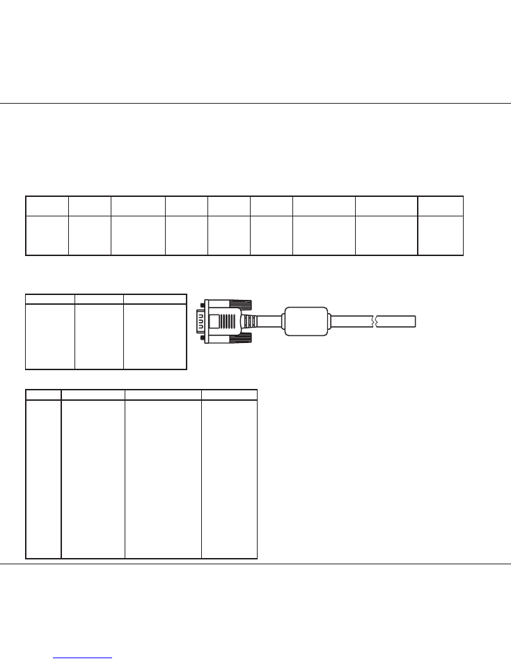
2.6.1
SPARC-Bus Cable
The table below describes the max. length of the SPARC-bus cable for the power supply for one handset unit.
The length of the cable depends on the number of supply wires and the wire thickness. The table shows the cable
lengths for systems with a supply voltage of +12V. If the system supply voltage is 24V, i.e. the supply voltage is provided
through N420, the max. cable length listed in the table may be doubled.
Number
System
Number of
From
To
Wire
Number of wires Number of wires Max.
supply
wires in cable
mm2
- BATT OVDC
+12VDC
length
+12 Volt
2x8
BOX
HOOK
0.25
2
2
30 metres
+12 Volt
2x8
BOX
HOOK
0.50
2
2
60 metres
+12 Volt
2x8
BOX
HOOK
0.75
2
2
100 metres
56.114
+12 Volt
2x8
Transceiver HOOK
0.14
3
2
5 metres
The SPARC-bus cable length is limited by the level of output power delivered to a connected external speaker on the
LS_2 terminals. The speaker output power depends on cable length and cable thickness as described in the table
below.
Wire [mm2]
Length [m]
Max. Power [W]
0.14
5
3.4
0.25
10
3.2
0.25
20
2.0
0.50
20
3.2
0.50
40
2.0
0.75
30
3.2
0.75
60
2.0
35356
56.114
SPARC-bus/Option cable 5 metres 56.114
Pin no.
Name
Colour
Twisted pair
pin 1
SUPPLY_ON
Red/White
7
pin 2
SPARC+
Yellow
1
pin 3
SPARC-
Yellow/Black
1
pin 4
AF+
Blue/White
2
pin 5
AF-
Blue
2
pin 6
-BAT_0VDC
Red and Orange
7/8
pin 7
+12VDC
Orange/White
8
pin 8
RX_AF+
Green/White
3
pin 9
RX_AF-
Green
3
pin 10
+12VDC
Black/White
6
pin 11
LS_1+
Brown
4
pin 12
LS_1-
Brown/White
4
pin 13
-BAT_0VDC
Black
6
pin 14
LS_2+
Purple
5
pin 15
LS_2-
Purple/White
5
Shield
Shield
9945
11
Installation
RT4722
2.6.2 Options Connector H4992
Options connectors
Transceiver unit
Twisted
Option box
X2
Name
pair
X1,X2
pin 1
DSC_ALARM_ON
1
pin 2
NMEA_OUT+1
1
Optional
pin 3
NMEA_OUT-1
1
Optional
pin 4
NMEA_IN+
2
4
pin 5
NMEA_IN-
2
5
pin 6
-BAT_0VDC
3
6
pin 7
+12VDC
3
7
pin 8
FAN_ON
8
pin 9
RX_1_SQ
9
pin 10
CH_AUX_1
10
pin 11
CH_AUX_1
11
pin 12
RX_1_AF
12
pin 13
N.C.
13
pin 14
N.C.
14
pin 15
N.C.
15
35350
NMEA_IN+
NMEA_IN-
-BAT
+12VDC
FAN_ON
RX_1_SQ
CH_AUX_1
CH_AUX_2
RX_1_AF
NMEA_OUT+
NMEA_OUT-
DSC_ALARM_ON
X1
14
15
13
12
11
10
X2
9
8
7
6
5
4
1
3
2
To connect a GPS to the VHF transceiver, connect
the GPS signal lines to the options connector
pin_4 (NMEA_IN+) and
pin_5 (NMEA_IN-).
Alternatively the GPS can be connected directly
to the transceiver by means of a 15-pole high
density D-sub which is supplied with the radio,
in the same pins as those mentioned above.
(NMEA_IN+ and NMEA_IN-) To fasten the D-sub
on the transceiver, use the special 15 to 15-pole
adaptor, also supplied with the radio.
35407A
GPS
H4992
56.111
SPARC-BUS
HANDSET
PRINTER
OPTION
/
Tx
Rx
12V DC
9945
12
Installation
RT4722
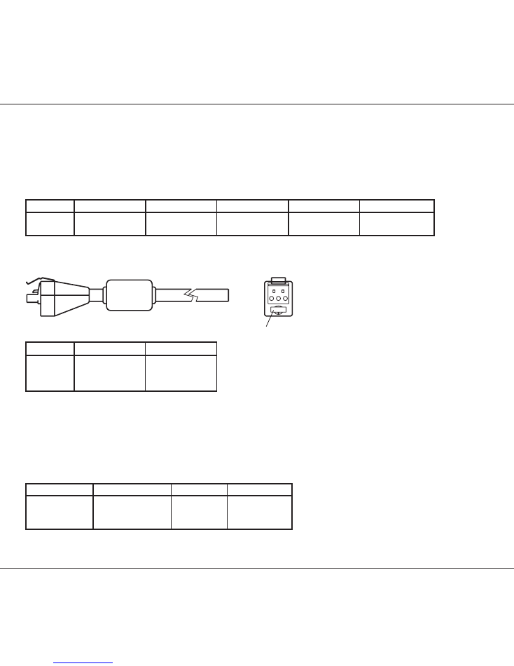
2.7
Cable Length
The cable length specified below is the absolute maximum length.
2.7.1
Power Cable
Number
Supply
From
To
Wire mm2
Max. length
56.112
+12 volt
BATTERY
RT4722
2.5
1.5 metres
+12 volt
BATTERY
RT4722
5.0
3 metres
Note: The cable length from battery to N420 depends on the wire thickness, but the voltage at the cable end at N420
should not be less than 18 volt.
35355A
10
3
2
1
Spare 10A fuse
Pin no.
Name
Colour
Pin 1
SUPPLY_ON
Blue
Pin 2
+BAT
Red
Pin 3
-BAT
Black
2.8
Electrical Connections
2.8.1
Power Connectors
Power Connectors
Transceiver unit
Name
Battery
N420
pin 1
SUPPLY_ON
NC
SUPPLY_ON *
pin 2
+Battery, +12VDC
+
+12V
pin 3
-Battery, 0VDC
-
0V
* NB! The blue wire is only to be used in connection with N420
9945
13
Installation
RT4722
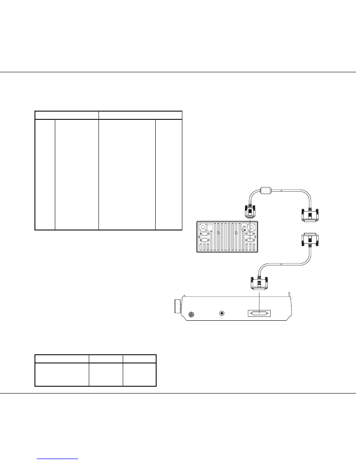
36282
Printer
56.127
VHF-DSC
Standard
printer cable
SPARC-BUS
HANDSET
PRINTER
OPTION
/
Tx
Rx
12V DC
2.8.2 Interconnection Cable Specification For VHF Printer Connection
Printer Cable 56.127
15-pole SUB-D male
25-pole SUB-D female
pin 1
LPT_Error
pin 15
-Error
pin 2
LPT_Init
pin 16
-Init
pin 3
LPT_D1
pin 3
D1
pin 4
LPT_D4
pin 6
D4
pin 5
LPT_D7
pin 9
D7
pin 6
-BAT_0VDC
pin 14
-Slct in
pin 6
-BAT_0VDC
pins 18,19,..(to)..24,25 -Gnd
pin 7
LPT_Str
pin 1
-Strobe
pin 8
LPT_D0
pin 2
D0
pin 9
LPT_D3
pin 5
D3
pin 10
LPT_D6
pin 8
D6
pin 11
LPT_Busy
pin 11
Busy
pin 12
LPT_Select
pin 13
Slct
pin 13
LPT_D2
pin 4
D2
pin 14
LPT_D5
pin 7
D5
pin 15
LPT_Auto_Feed
pin 14
-Auto fd
For the connection to the printer you have to connect
the 15-pole SUB-D male to the VHF units printer
connection and the 25-pole SUB-D to a
standard printer cable (25-pole SUB-D - Centronic)
2.9
Compass Safety Distance
Unit
Standard
Steering
VHF-DSC DUPLEX 1.3 m
0.8 m
N420
0.6 m
0.3 m
N163S
1.2 m
0.7 m
9945

14
Installation
RT4722
2.10
Test Procedure TX/RX DSC Call
To test the system’s DSC functionality, enter the function menu and perform two test calls: (INTernal test) and
(EXTernal test).
Internal test call: (The call is looped back internally, no activation of transmitter or receiver)
This test controls the DSC modem in the transceiver RX and TX internally.
1.
Hook off handset.
2.
Enter function menu: Func\dsc\testcalls\int path. Select call by “arrow right” key.
3.
“Transmit” the call by keying “Send call”.
4.
The display will show in sequence: TX-CALL, TX-OK.
5.
The call is announced by the DSC modem. Read the call info in RX-LOG.
External test call: (The call is transmitted and received using the aerials).
This test also controls the hardware of transmitter and receiver boards.
1.
Hook off handset.
2.
Enter function menu: Func\dsc\testcalls\ext path. Select call by “arrow right” key.
3.
“Transmit” the call by keying “Send call”.
4.
The display will show in sequence: TX-CALL, TX-OK.
5.
The call is announced by the DSC modem. Read the call info in RX-LOG.
9945