Full Text Searchable PDF User Manual
Centrale téléphonie
Z.A de la Croix saint-Mathieu
B.P.10022 - 28320 GALLARDON - FRANCE
Tel. (33) 02 37 33 69 69 - Fax. (33) 02 37 31 02 17 67
e-mail : info@saaa.fr
Update : 7/2/11
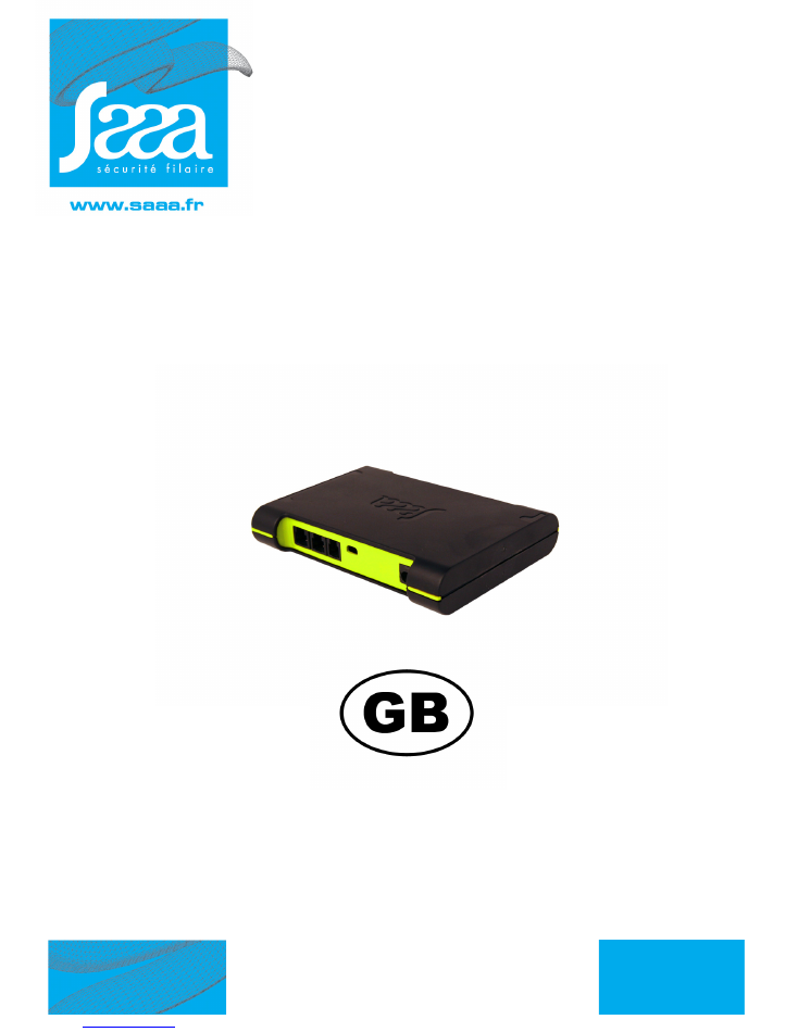
ALTEA 3 - BUS
USER’S GUIDE
USER’S GUIDE
Altea 3 BUS CONTROL UNIT
OZ NOT GB 0906
and ALTEA 3 - BUS - DS
option alarm report
page: 2
Mise à jour du : 7/
0Z NOT FR 00906
Vitrea
USER GUIDE
Thank you to have granted your confidence to us by buying a power station of alarm SAAA. This pro-
duct was manufactured in the respect of the highest standards of quality. For a better use of your
power station "Altea 3 BUS", we advise you to read the instructions attentively.
You can help protect the environment!.
Please remember to respect the local regulations: hand in the non-
working electrical equipments to an appropriate waste diposal
center. take out the batteries before scrapping the product.

page: 3
Mise à jour du : 7/2/11
0Z NOT FR 0906
Vitrea
USER GUIDE
Getting Started ............................................................................................ 4
General cablage .................................................................................................4
Altea 3 connections (front and rear views) ..............................................................4
The IR receiver / LCD display ........................................................................ 5
Information provided by the 8 segments digit 53550: .............................................5
Other information: ...............................................................................................5
Maximun capacity of the ALTEA 3 BUS control unit installation ................................5
Displayed at the start ............................................................................................6
Display the number of distributors and sensors .......................................................6
Functions of Red and green LEDs ..........................................................................6
Functions of distributor LED : ................................................................................6
First startup. ................................................................................................ 7
Plug & Play procedure .................................................................................. 8
Control Unit Initializing .........................................................................................8
Distributors Programming .....................................................................................8
Maintenance procedure ............................................................................... 8
Programming ......................................................................................................8
Blanking .............................................................................................................9
Option : Alarm report .................................................................................. 9
Adding a product to an existing configuration .............................................. 11
Alarm management ................................................................................... 12
Repair mode ............................................................................................. 13
Alarm default BUS .............................................................................................14
Stop the Altea 3 (not recommended) ........................................................... 15
Resetting the configuration ......................................................................... 15
Removing products from the installation ...................................................... 15
Adding a distributor ................................................................................... 17
Key usage ................................................................................................. 18
Getting started ..................................................................................................18
Associating a RED key to a Altea 3 (when the blue key is allready allocated) ...........19
Associating blue, green or yellow keys to a Altea 3 ...............................................20
Deleting a key from the Altea 3 ...........................................................................21
Changing the batteries ............................................................................... 21
Special procedure: what to do if I have lost my red key ! ............................... 22
Digital Signage option ............................................................................... 24
Computer connection via USB ............................................................................24
Kit includes Digital Signage Saaa ........................................................................24
page: 4
Update : 7/2/11
0Z NOT FR 0906
Vitrea
USER GUIDE
1.0/ Getting Started
1.1/ General cablage
1.2/ Altea 3 connections (front and rear views)
Graph001
Altea 3 BUS
control unit
IR Receiver
and display
53550
52952
52909
52916
50630
50635
56ANA1010 - 56ANA2020
51511
Power supply
Distributors
ON/OFF
BLUE IR KEY
ON/OFF
BLUE IR KEY
Sensors
BUS lenght maxi = 15 m
Graph002
01 02 03 04 05 06 07 08
Optional
USB Output
REAR
VIEW
FRONT
VIEW
BUS Output
(to distributors and/or
IR receiver
and display)
53550 only
Anti-motion
Sensor
Power Supply
Sensor
page: 5
USER GUIDE
Update : 7/2/11
0Z NOT FR 0906
Vitrea
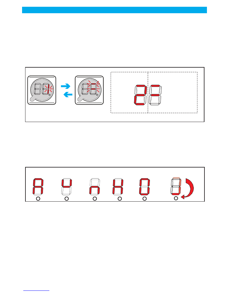
2.0/ The IR receiver / LCD display
The display consists of two 8 segments digit and a dot. It will provide information on your installation, how
it is configured, and will assist in solving problems. This BUS C.U does not work with the 53500 I.R receiver
2.1/ Information provided by the 8 segments digit 53550:
On some occasions (described later on in this user's guide), the display will be toggling between a number
(1 to 8) and a 3 horizontal bars pattern. The number relates to the sensor ("3" means the sensor that is
plugged into input 3). The 3 horizontal bars will tell what is connected and stuck to the product as shown
below
PLEASE NOTE THAT ON THE STANDARD Altea 3 THE BOTTOM BAR WILL NEVER
BE LIT SINCE THERE IS NO PROTECTION ON THE POWER SUPPLY.
Information provided by the dot:
Dot NOT lit: the control unit is OFF, nothing is protected
Dot blinking slowly (every second): control unit ON, no problem detected
Dot blinking quickly: control unit ON, but there is at least one problem that has been detected
2.2/ Other information:
(*) It has NO key associated with it and it has NO configuration in memory
whatsoever.
2.3/ Maximun capacity of the ALTEA 3 BUS control unit installation
1 control unit
9 distributors
2 IR receiver and display
15 mèter BUS lenght maxi
Graph003
The product
having a problem
The LCD display
toggles between
> Mid digit is lit:
Main sensosr
is not working
> Mid digit is lit:
Main sensosr
is not working
The type of
problem
> Top digit is lit:
Nano sensor
is not working
> Top digit is lit:
Nano se
nsor
is not working
type of problem
distributor number
Right digit
Left digit
Graph003b
Clockwise revolving
= control unit blanck (*)
A = ALARM
U = Mains power
supply is OFF
n = WEAK
BATTERIES
H = n + U
O = Control unit
open
page: 6
Update : 7/2/11
0Z NOT FR 0906
Vitrea
USER GUIDE
2.4/ Displayed at the start
In the first operation of the control unitdisplay alternately shows the following information:
This function does not affect the first operation
2.5/ Display the number of distributors and sensors
After a long press of more than 5 seconds with the green remote control the control unit display alternately
the number of distributors, present sensors and stik sensors on the installation:
2.6/ Functions of Red and green LEDs
GREEN LED:
- Indicates the presence of the power.
- Flashes when the control unit is operating.
- Indicates the absence of the power by a flash every15 seconds when the control unit is operating..
RED LED:
- It is on continuously when the control unit is not yet initialized (no badge is associated).
- Indicates the shutdown of the control unit when it is powered by two flashes every second.
2.7/ Functions of distributor LED :
- On all time = the distributor is not programming.
- Blinks every seconds = the distributor is programming, but does not communicate with control unit
- Emits a flash every 50ms = the distributor communicate with the controle unit «without» external power
supply
- Emits two flashs every 50ms = the distributor communicate with the controle unit «with» external power
supply.
Graph003c
Number of
distributors
empty
Number of
sensors
First failure
to inhibit
Second failure
to inhibit
empty
etc ...
Numbre de
PRESENT
sensors
Nombre de
Stik
sensors
empty
The central
restart
normally
Graph003d
Number of
distributors
empty
Number of
PRESENTS
sensors
Number of
STICK
sensors
empty
Remote control
button
GREEN
+ de
5
’’
The central
restart normally
page: 7
USER GUIDE
Update : 7/2/11
0Z NOT FR 0906
Vitrea
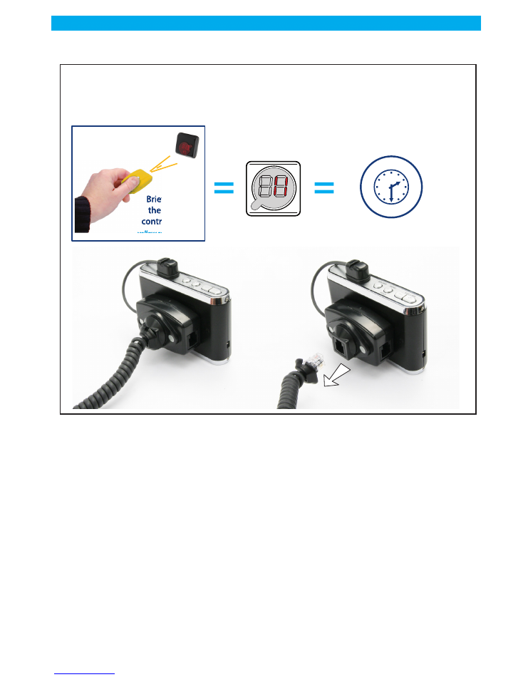
3.0/ First startup.
1 -
Opun the battery compartment
2 -
Insert 3 standard AA batteries into the control unit
3 -
Close the battery compartment.
4 -
Connect the IR receiver / display to the control unit
At this stage, you may want to already connect up to 8 sensors to the control unit or you may want
to power it up with no sensors and add them one by one later while the control unit is ON. Wha-
tever you choose, the control unit will behave the same at the first power up:
5 -
Connect the power supply.
6 -
The display will show the clockwise revolving digits
7 -
ASSOCIATE at least one blue key to the control unit
Once this is done, the Altea 3 will start operating and the display will show the slowly blinking dot.
8 -
Install mode: the Altea 3 will then browse through its 8 inputs, starting from input
1. When it finds a sensor with every possible protection properly applied (ie both the
main and nano sensors properly stuck for the Altea 3, or the main, the nano and the
power supply sensors for the Altea 3 Pro) it just skips to the next input (if all 8 inputs
have all sensors and all protections properly applied, then the control unit will just
start its operation).
Graph004
1
2
3
Graph005
4
5
Graph005b
> the LCD display
digits are sequentially
lit clockwise
> the LCD display
digits are sequentially
lit clockwise
Only the first time
the system is powered
Brifly press
the remote
control button
Brifly press
the remote
control button
Blue remote control
Blue remote control

page: 8
Update : 7/2/11
0Z NOT FR 0906
Vitrea
USER GUIDE
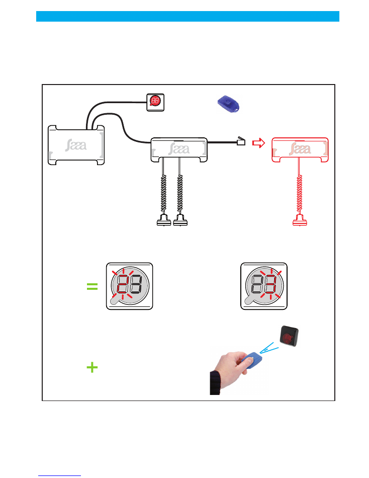
4.0/ Plug & Play procedure
4.1/ Control Unit Initializing
Start the Control Unit (without connecting sensors or with sensors connected but not stuck) without connec-
ting distributors. The left display show nothing and the middle dash blink on the right display (internal dis-
tributor). Press the blue remote control to validate the internal distributor (address 0). If the Control Unit is
started with at least one sensor stuck, it will display the first defective sensor fully or partially unstuck and
you will have then to validate all the defective points from 1 to 8.
After Validation, the left display show " 1 " blinking and nothing on the right display because no distributor
is connected. Press the blue key to validate the missing distributor and then repeat this operation till the
display show the decimal point blinking meaning that the Control Unit is running.
4.2/ Distributors Programming
When the control Unit is running, connect the first virgin distributor (without connecting sensors or with sen-
sors connected but not stuck) whose red LED is alight. The left display show number "1" blinking and the
right display show the middle dash blinking indicating that it will validate automatically this distributor at
the address " 1 " in 30 seconds, in the meantime, one bip will be emitted every 5 seconds. If you agree,
you can speed the procedure validating with the blue remote control and stick label "1" on it then repeat
this operation with all the distributors you have in the limit of 9.
Warning, if the connected distributor has at least one sensor stuck, the Control Unit
will not take care of them and the validation of the Distributor will validate also the
connected sensors
In the Plug & Play procedure, it is not possible to allocate distributors leaving blanks (i.e.: 1, 3, 5, 7, 9) the
addresses proposed by the Control Unit are in order (1,2,3,4,5,6,7,8,9).
When a distributor is operating, the LED blinks briefly every second.
WARNING, you never must connect in the same time several virgin distributors to
the Control Unit because they will get the same address and will generate false
alarms.
5.0/ Maintenance procedure
5.1/ Programming
This procedure allows programming the distributors one by one, which means only one distributor can be
connected to the Control Unit in the same time. If several virgin distributors are connected in the same time
the LED of each distributor which normally must lit continuously will blink randomly.
To enter this procedure, you need to have a Yellow remote control allocated to the Control Unit and stop it
pressing 5 seconds on the blue remote control.
You must wait to be on the right menu and on the right address to connect the distributor.
Press briefly on the yellow remote control and you see number " 1 " on the right, meaning you are at the "
ringing " menu level, press briefly a new time on the yellow remote control and you reach the level of the
cycling power menu, press briefly for the third time on the yellow remote control and you are at the pro-
graming distributor menu. Press 2 seconds the remote control and the left digit display the number " 1 "
blinking and the right digit displays nothing. You have to press as much as necessary to reach the number
you chosen and then connect the distributor (virgin or already programmed) which will get the current ad-
dress stabilizing the display. Sticks the corresponding label and disconnect it, you will see on the left digit
display the following number blinking and, if you do nothing, the control unit exit the programing mode
after 5 seconds.

page: 9
USER GUIDE
Update : 7/2/11
0Z NOT FR 0906
Vitrea
If you wish program several distributors in this mode, press briefly as much as necessary to reach the number
you chosen or do nothing if the chosen address is the following and, within 5 seconds, connect the distri-
butor which will get this new address and stabilize the display. Repeat this operation as much as necessary.
When you reach the n° " 9 ", the following number will be n° 1. After having addressed Distributor n° 9,
when you disconnect the distributor, the left digit display n° " 1 ". The current number blinks for 5 seconds
allowing eventually programming of the following distributor. If you do nothing, the Control Unit will exit
the programming mode after 5 seconds.
5.2/ Blanking
This procedure located on level " 4 " of the maintenance menus after the programming 3rd level allow to
erase one several distributors at the same time. You have just, Control Unit in the stop mode, to press
briefly 4 times on the yellow remote control to see the number "4" on the right digit. Press 2 seconds on
the yellow remote control to put all the distributors connected to their default address (virgin distributor
with the red LED lighting) and exit the blanking mode.
6.0/ Option : Alarm report
The alarm report is located on the contact 1 & 4 of the anti-displacement Plug
This is a dry N/O contact which is closed when there is a problem
This contact is activated in the following cases:
> Self-protection default
> Bus Default
> Sensors default
> Distributor Default
> Anti-displacement
> Connection of a TOR Sensor
page: 10
Update : 7/2/11
0Z NOT FR 0906
Vitrea
USER GUIDE
At the end of this procedure, the configuration of your installation will be kept in memory by the con-
trol unit (even if the control unit is switched off), and whatever discrepancy with this memorized
configuration will trigger an alarm.
Graph005c
IF what the LCD display tells you,
is what you wanted
(for example you did not
want any telephone on position 1),
VALIDATE
IF what the LCD displays tells you is NOT
what you wanted
(for example, you stuck a nano sensor
on telephone 8, but top digit is lit
(= nano sensor not working),
CORRECT THE PROBLEM
The LCD display automatically
shows the next position on which there is either a missing telephone
or a non working sensor, if any.
If only one telephone is missing or one sensor is not working
> Renew the above steps for each position, until the LCD display shows the blinking red dot.
> System is up and running, fully protected as per your needs.
(*) ALWAYS USE A NEW ADHESIVE WHEN RE-STICKING A SENSOR
Simply add what is missing,
and/or properly re-stick the faulty sensor
(*)
> Mid digit is lit:
Main sensosr is not working
> Mid digit is lit:
Main sensosr is not working
Type of non-working
sensor
> Top digit is lit:
Nano sensor is not working
> Top digit is lit:
Nano se
nsor is not working
Briefly press
the remote
control button
Briefly press
the remote
control button
Blue remote control
Blue remote control
3’'
Automatic acknowledgement
after 3 secs
Automatic acknowledgement
after 3 secs
The product
having a problem
The LCD display
toggles between
The type of
problem
Distributor number
failed
Exemple d’installation en défaut
page: 11
USER GUIDE
Update : 7/2/11
0Z NOT FR 0906
Vitrea
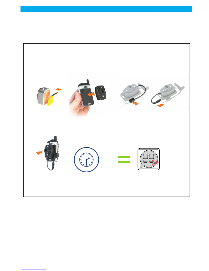
7.0/ Adding a product to an existing configuration
Adding products is automatic. Just stick the appropriate sensors on the product you want to add and connect
it to the control unit.
After 30 seconds, a beep will be heard, telling that the control unit has taken the new product into account.
The display will show what has been detected, toggling between the product number and the 3 bars pattern
(cf graph 005c), and a beep will be heard every 5 seconds.
You will need to validate the addition just like when you validated the various positions at first startup, by
pressing on a valid blue or green key. However, if you don't, the Altea 3 will automatically validate what
it has detected after 30 secs, and the beep will stop.
The new configuration will then be memorized, taking the addition into account.
Graph006
Peel the plastic
film off
Peel the plastic
film off
ADD A PRODUCT
3’'
After 30 secs, the control unit restarts
its operation normally
Taking addition
into account
Stick
the main sensor
Stick
the main sensor
Connect
the power cord
Connect
the power cord
Plug into
Altea 3 or Distributor
Plug into
Altea 3 or Distributor
Stick
the nano sensor
Stick
the nano sensor
Or riefly press the remote control button
Or riefly press the remote control button
1 Bip for the main sensor
2 Bips if a nano sensor is also connected
1 Bip for the main sensor
2 Bips if a nano sensor is also connected
page: 12
Update : 7/2/11
0Z NOT FR 0906
Vitrea
USER GUIDE
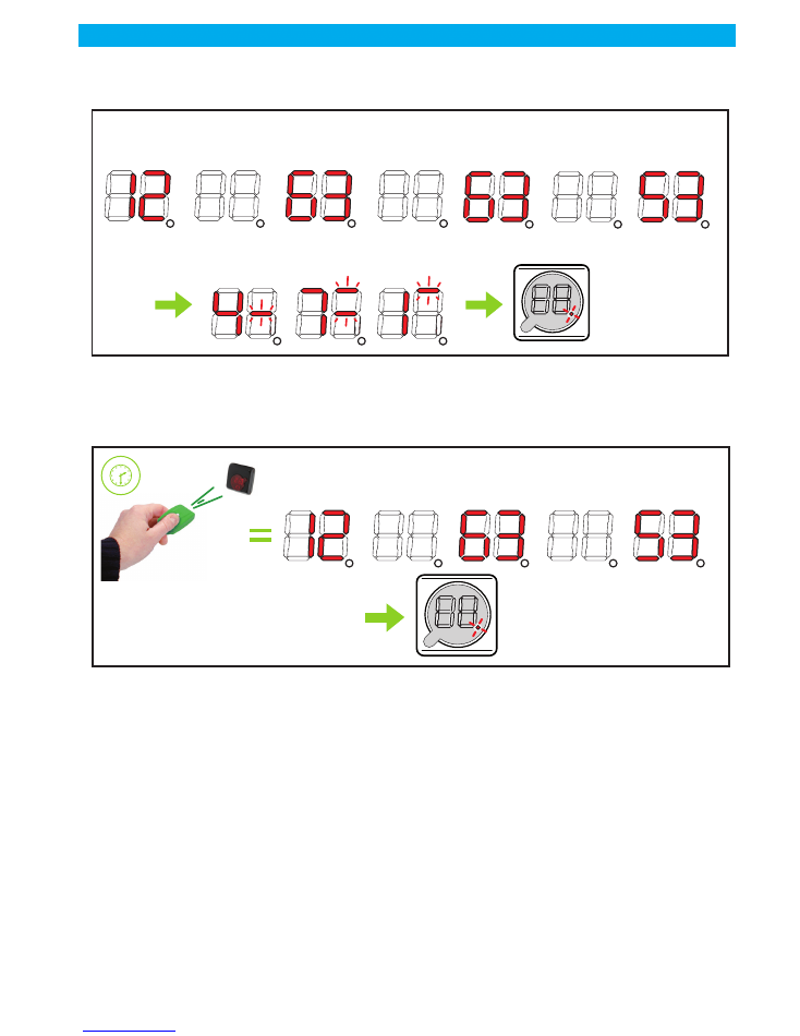
8.0/ Alarm management
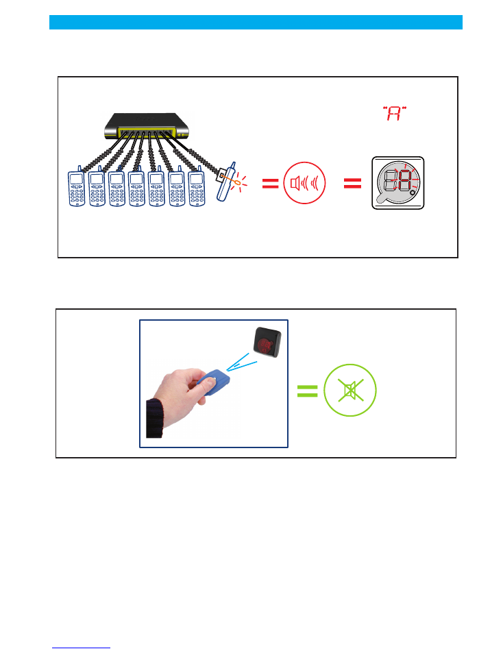
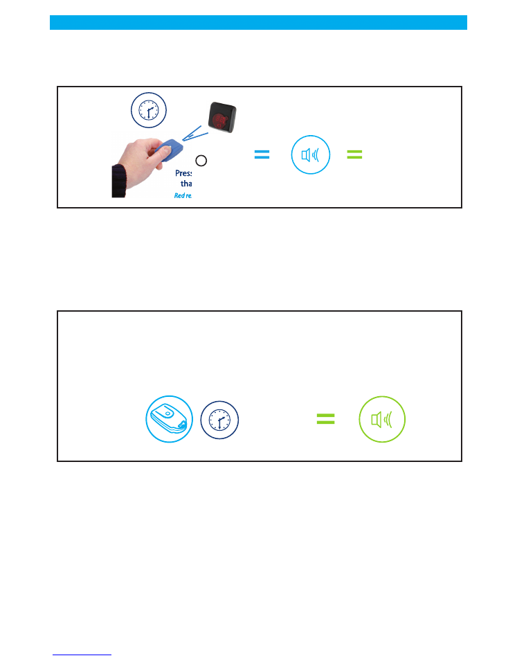
When an alarm is triggered, a loud audio sound will be heard and the display will show a "A".
It is of course highly recommended to immediately look around and find out if anyo-
ne is trying to tamper with the system.
To stop the alarm sound, briefly press on a blue or green key.
Caution: by doing so, you are also inhibiting the particular sensor that trigge-
red the alarm (the nano sensor of telephone #8 in the above example). That
means that you have lost the protection brought by this sensor until you fix
the problem.
It is therefore highly recommended that you fix the problem immediately (cf graph 009).
However, if you really don't have time to, you will be able to fix it later (not recommended). In the meantime,
all other products remain fully protected.
If there is at least one sensor that has been inhibited, the dot on the LCD will blink more quickly, meaning:
"there is at least one problem that needs to be fixed".
Graph007
Theft attempt
Example: telephone n°8
ALARM !
1
1
2
2 3
3 4
4 5
5 6
6
7
7
8
8
Loud audio signal
Graph008
Stops
the audio
signal
Brifly press
the remote
control button
Brifly press
the remote
control button
Blue remote control
Blue remote control
All other telephones
remain fully protected
page: 13
USER GUIDE
Update : 7/2/11
0Z NOT FR 0906
Vitrea
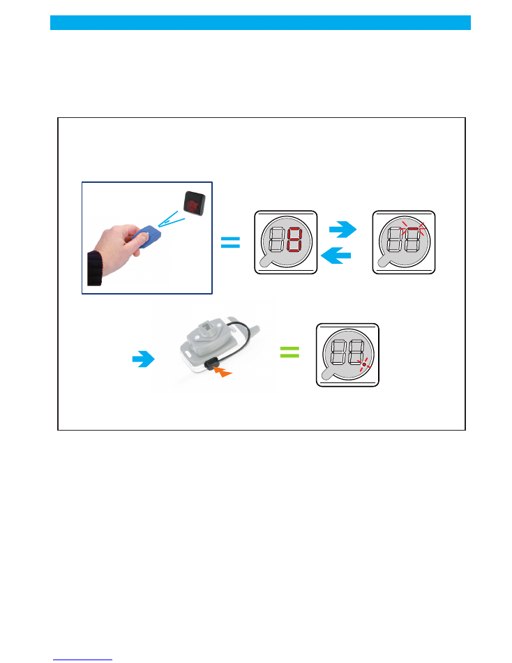
9.0/ Repair mode
A short press on a blue or green key while there is no alarm will enter the repair mode. If the Altea 3 finds
problems that require your attention it will indicate them through the LCD display:
Fix the designated problem (generally by properly re-sticking the sensor, using a new adhesive) . The Altea
3 will then move to the next detected problem. When all problems are solved, the display shows the slowly
blinking dot again.
Graph009
REPAIR MODE
The LCD display toggles between the number
of the position where a problem was
detected and the type of problem
The control unit restarts
its operation normally
Fix the problem(s)
Briefly press
the remote
control button
Briefly press
the remote
control button
Blue remote control
Blue remote control
page: 14
Update : 7/2/11
0Z NOT FR 0906
Vitrea
USER GUIDE
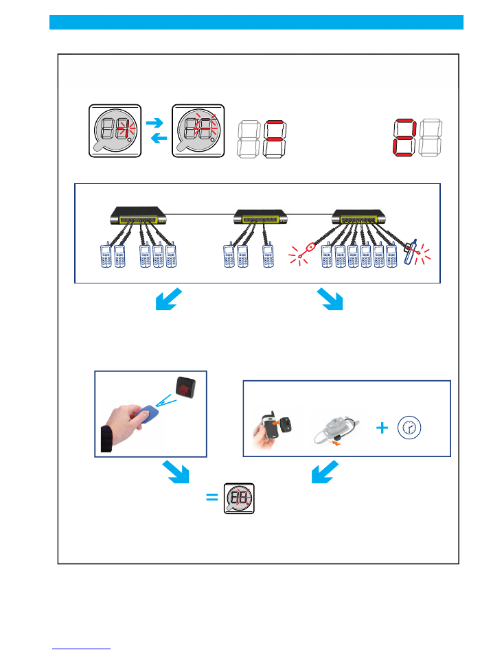
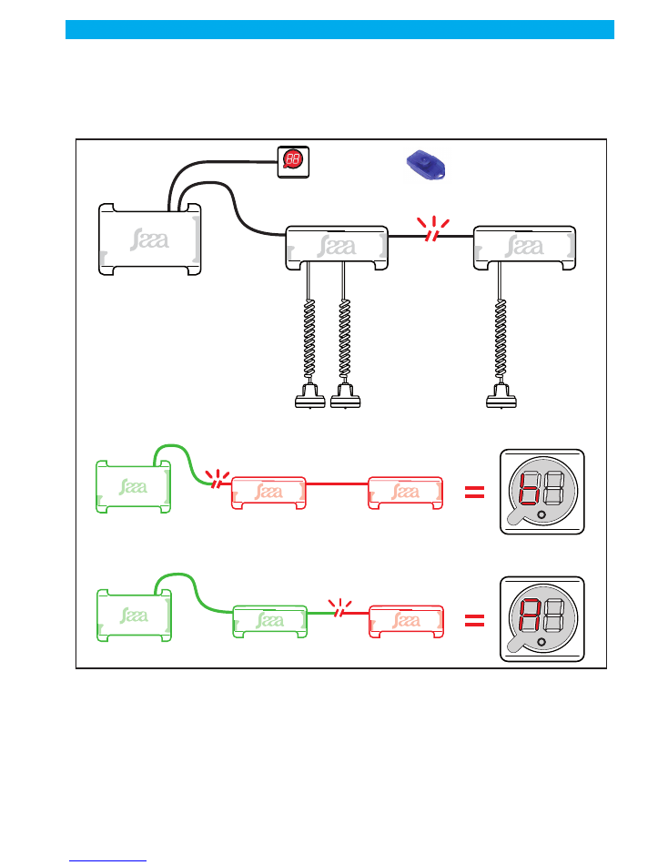
9.1/ Alarm default BUS
In case of default BUS, the alarm goes on and can be stopped by IR Key only after the default disappears.
The display shows an "A" on the left digit of the display if some distributor have disappeared.
The display shows ana "b" if all distributors cannot communicate.
There's no display when communication is restored on the bus.
Graph0092
IR Key
Défault
BUS
IR receiver
and display
ALTEA 3 BUS
Controle Unit
BUS distributor
SAAA
Sensors
BUS distributor
The display shows a "b" if
NO
distributor is recognized by the control unit.
The display shows a "b" if
NO
distributor is recognized by the control unit.
The display shows a "A" if
PART
distributor only is recognized by the control unit.
The display shows a "A" if
PART
distributor only is recognized by the control unit.
ALTEA 3 BUS
Control Unit
BUS distributor
BUS distributor
Défault
BUS
Défault
BUS
ALTEA 3 BUS
Control Unit
BUS distributor
BUS distributor
page: 15
USER GUIDE
Update : 7/2/11
0Z NOT FR 0906
Vitrea
10.0/ Stop the Altea 3 (not recommended)
Caution: stopping the control unit will leave all products un-protected.
11.0/ Resetting the configuration
A long (more than 10 secs) press on the blue key will stop the control unit (=nothing protected), and com-
pletely reset the Altea 3 configuration (that was memorized during the installation phase and by further
adding products). This operation does’nt remove the keys.
The next time the Altea 3 is switched on (by pressing a valid key), it comes back to the "install mode" as
described in "first startup, 8)". Follow the steps described in first startup 8), until a new configuration is me-
morized.
12.0/ Removing products from the installation
1 -
If you own a yellow key:
Press on the yellow key. The display will show a specific pattern (cf. graph009) and a beep will be heard
every second. You have 10 seconds to take whatever product/sensor off the installation. This will not trig-
ger an alarm and the new configuration, taking the removal into account, will be memorized. Each time
you take a product off, you again have 10 seconds to remove another one if you wish.
Note: the yellow key allows a convenient and easy removal of products, the control
Graph009b
Pressing more
than 5 secs
Pressing more
than 5 secs
Red remote control
Red remote control
5’'
3 audio beeps
CONTROL
UNIT
“OFF”
1
Graph010
RESET THE CONTROL UNIT CONFIGURATION
5’’ long beep
Long press
on the remote control
Long press
on the remote control
Blue remote control
Blue remote control
+
than
10’'
page: 16
Update : 7/2/11
0Z NOT FR 0906
Vitrea
USER GUIDE
unit being still switched ON (= all products are duly protected).
2 -
If you don't own a yellow key, the only way to take products off the installation is
to perform a configuration reset with your blue key as described in "resetting the con-
figuration".
When the reset is done and the Altea 3 is off, remove whatever you want from your installation, re-
shuffle everything as you wish, then start the Altea 3 again (by pressing whatever valid key) and
follow the install mode steps as described in "start-up 8)" to validate your new configuration.
Graph009
REMOVING PRODUCTS
The LCD display will
show a specific pattern
You have 5 seconds
to take product off
Briefly press
the remote
control button
Briefly press
the remote
control button
yellow remote control
yellow remote control
5’'
page: 17
USER GUIDE
Update : 7/2/11
0Z NOT FR 0906
Vitrea
13.0/ Adding a distributor
Distributors will be taken automatically after the connection on the bus when the controle unit is operating.
There will be a 30 second delay before taking effect. There will be flashing digit left (number distributor)
during this phase.
.
Distributors will be taken an virgin address or an address between 1 and 9
Graph011b
ON/OFF
BLUE IR KEY
IR Receiver
and display
ALTEA 3 BUS
control unit
BUS distributor
BUS distributor
When you connect the distributor
to add, the number one
flashes on the left digit
When you connect the distributor
to add, the number one
flashes on the left digit
The right digit indicates the first
sensor connected and considered
on this new distributor
The right digit indicates the first
sensor connected and considered
on this new distributor
Confirm
consideration
distributor
by a short press
on the remote blue
Confirm
consideration
distributor
by a short press
on the remote blue
Short press
Short press
Remote control button
Remote control button
page: 18
Update : 7/2/11
0Z NOT FR 0906
Vitrea
USER GUIDE
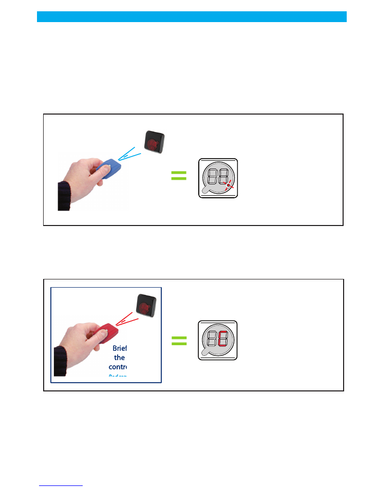
14.0/ Key usage
14.1/ Getting started
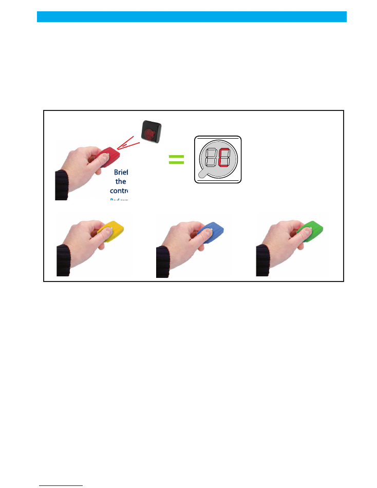
If your Altea 3 is brand new or if it has been totally reset (configuration and key reset), the display will show
clock wise revolving digits.
That means that NO key is currently associated to (= known by) the control unit. In that state, only a blue
or red key can be recognized and associated to the Altea 3, which means you have two options:
Option 1: associating a blue key (with red key)
Just take a blue key and press the button. A beep will be heard and the blue key will automatically be asso-
ciated to the control unit. The Altea 3 will be switched ON and will start a new configuration check as
described in the first startup user's guide (“First startup.”, page 7). Follow the steps from there.
Option 2: associating a red key (control unit blank)
This option is generally chosen when you want to quickly re-associate all the keys you own to a Altea 3 that
has been totally reset (configuration + keys reset).
Just take a red key, press the button. A beep will be heard, the display will show a "C" (like configuration),
and the red key will automatically be associated to the control unit. From there, you need to associate other
keys to your Altea 3, otherwise you will just stay in this configuration mode (with the "C" still displayed) and
will not be able to use the control unit.
Just associate the other keys you have to the Altea 3 by following the relevant procedure (“Associating blue,
green or yellow keys to a Altea 3”, page 20).
Graph012
Briefly press
the remote
control button
Briefly press
the remote
control button
Blue remote control
Blue remote control
The display shows
the slowly
blinking dot.
The display shows
the slowly
blinking dot.
> CONTROL UNIT ON
> CONTROL UNIT ON
Graph014
Briefly press
the remote
control button
Briefly press
the remote
control button
Red remote control
Red remote control
> the control unit
start normally
> the control unit
start normally
point flashes slowly
page: 19
USER GUIDE
Update : 7/2/11
0Z NOT FR 0906
Vitrea
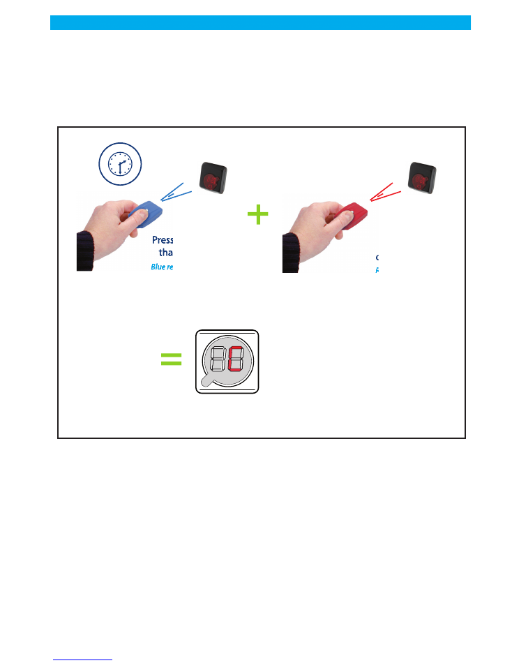
14.2/ Associating a RED key to a Altea 3 (when the blue key is allready
allocated)
1 -
switch the Altea 3 OFF (by pressing more than 5 secs on a valid blue key)
2 -
Short press on the red key: a C will be briefly displayed and the red key will be
associated to the Altea 3.
Note: a Altea 3 control unit can only have ONE red key associated to it. Attempting to associate a second
red key to a Altea 3 WILL NOT WORK.
Graph018
Pressing more
than 5 secs
Pressing more
than 5 secs
Blue remote control
Blue remote control
5’'
Short Press
Briefly press
the remote
control button
Briefly press
the remote
control button
Red remote control
Red remote control
> the LCD display
will show a “C”
(like configuration)
> the LCD display
will show a “C”
(like configuration)
The red key is
associated
to the control unit
page: 20
Update : 7/2/11
0Z NOT FR 0906
Vitrea
USER GUIDE
14.3/ Associating blue, green or yellow keys to a Altea 3
Have a valid red key + all the new keys you wish to associate to the control unit ready and next to you.
1 -
Whether the Altea 3 is ON or OFF, short press on a valid red key: the display shows
a C
2 -
You have then 5 secs to associate a new blue, green or yellow key to the Altea 3,
by just pressing on the key.
3 -
Renew step 2 until you have associated all the keys you wanted to. Each time you
press on a key to associate it, you have again 5 secs to enter the next key.
4 -
5 secs after you have associated the last key you wanted to, the display comes back
to normal.
Graph019
Short Press
Briefly press
the remote
control button
Briefly press
the remote
control button
Red remote control
Red remote control
> the LCD display
will show a “C”
(like configuration)
> the LCD display
will show a “C”
(like configuration)
or
or
or
or
page: 21
USER GUIDE
Update : 7/2/11
0Z NOT FR 0906
Vitrea
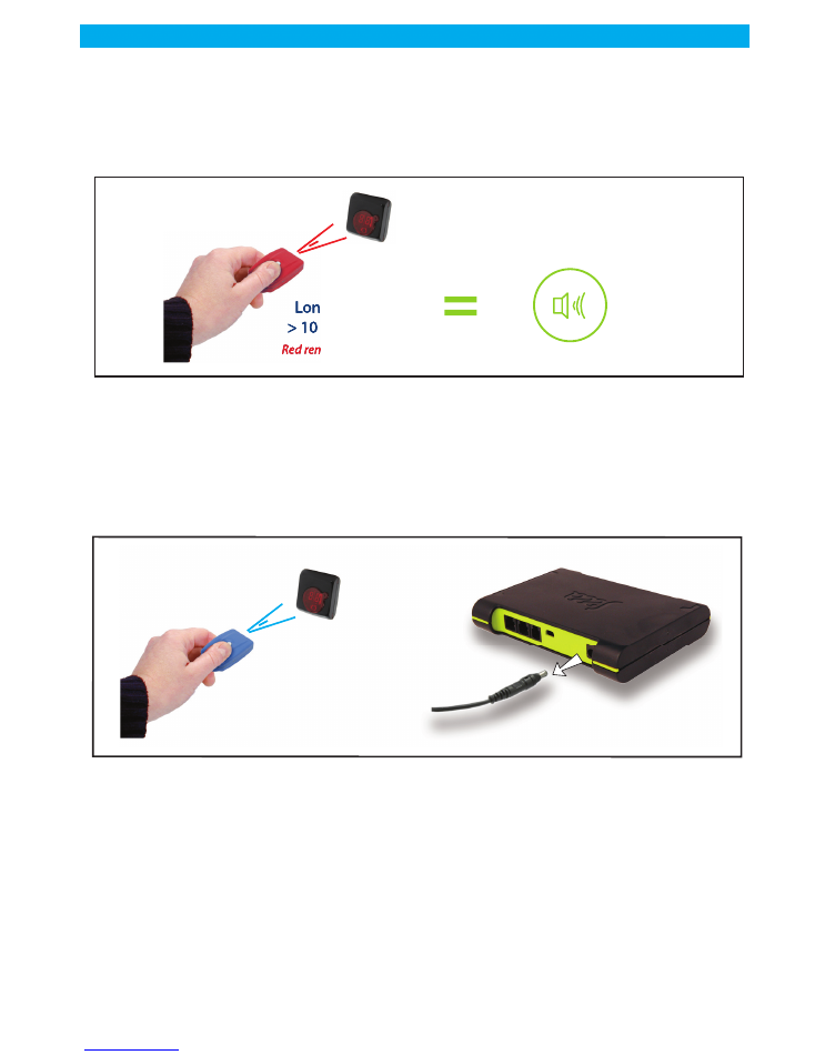
14.4/ Deleting a key from the Altea 3
There is NO WAY to remove the keys associated to a Altea 3 ONE by ONE. The only procedure is actually
to delete ALL keys at once, then to re-enter the keys you wish.
1 -
Long press on the red key (> 10 secs) until you hear a long (10 secs) beep (The
Altea 3 may be ON or OFF, it does not matter).
ALL keys have been deleted from the Altea 3 (including the red key you just used) AND the Altea 3 configu-
ration has been reset. The display shows the clockwise revolving digits.
2 -
Go to 1) option b, to quickly re-associate all other keys to your Altea 3.
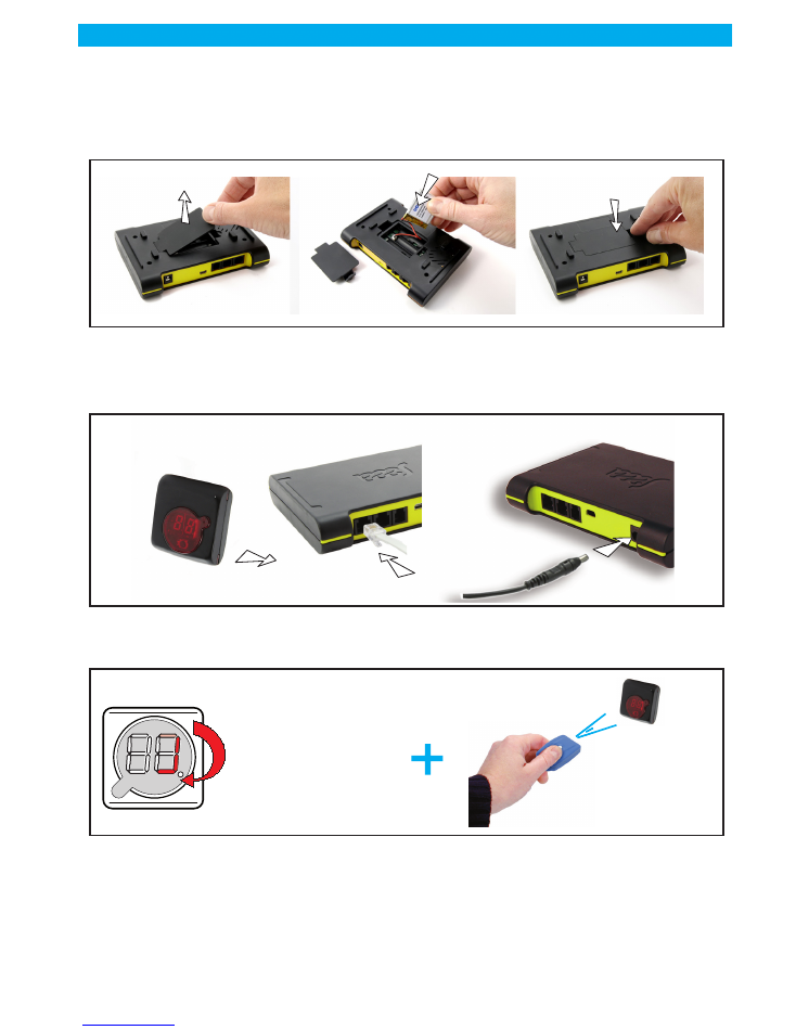
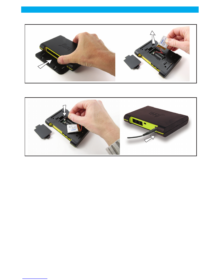
15.0/ Changing the batteries
1 -
Stop the control unit (“Stop the Altea 3 (not recommended)”, page 15)
2 -
Take the power supply off (3 beeps will be heard, meaning "mains power off")
3 -
Unscrew and remove the lid
Graph020
Long Press
Long press
> 10 seconds
Long press
> 10 seconds
Red remote control
Red remote control
> Your hear a long
“beep”
> Your hear a long
“beep”
10’’
Graph015
Briefly press
the remote
control button
Briefly press
the remote
control button
Blue remote control
Blue remote control
page: 22
Update : 7/2/11
0Z NOT FR 0906
Vitrea
USER GUIDE
4 -
Replace the batteries
5 -
Put the lid back into place and screw it
6 -
Reconnect the power supply, the Altea 3 automatically starts.
Note: if for any reason, you reconnect the power supply to the Altea 3 while the case is opened, you must
know that you have one minute to put the lid back into place, otherwise the alarm will be triggered and
the display will show "o" (open).
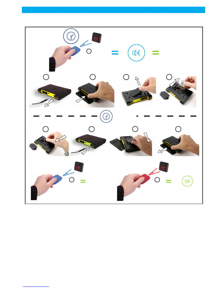
16.0/ Special procedure: what to do if I have lost my red key !
If you have lost your red key and want to enter a new red key into your Altea 3:
1 -
Stop the control unit
2 -
Take the power supply off (3 beeps will be heard, meaning "mains power off")
3 -
Unscrew the lid
4 -
Remove the lid
Graph016
Graph017
page: 23
USER GUIDE
Update : 7/2/11
0Z NOT FR 0906
Vitrea
5 -
take the batteries off WAIT ONE MINUTE
6 -
Put the batteries back into place
7 -
Connect the power supply
8 -
Put the lid back into place
9 -
Screw the lid
10 -
Press on the blue key = control unit OFF
11 -
Press on the red key you want to associate to the control unit.
Graph021
5’'
1 minute
1 x
2
1
3
4
5
6
8
7
9
10
centrale
à l’arrêt
11
Long press
CONTROL
UNIT
“OFF”
3 audio beeps
Pressing more
than 5 secs
Pressing more
than 5 secs
Red remote control
Red remote control
Short Press
Briefly press
the remote
control button
Briefly press
the remote
control button
Red remote control
Red remote control
1 audio
beeps
Pressing more
than 5 secs
Pressing more
than 5 secs
Pressing more
than 5 secs
Pressing more
than 5 secs
Red remote control
Red remote control

page: 24
Update : 7/2/11
0Z NOT FR 0906
Vitrea
USER GUIDE
17.0/ Digital Signage option
17.1/ Computer connection via USB
17.2/ Kit includes Digital Signage Saaa
Graph022
REAR VIEW
Altea 3 BUS
Control Unit
Optional
Output USB
Graph023
ALTEA 3 BUS - DS
control unit
Mini-USB
Soft Cd-Rom Digital Signage Saaa